


 OPTISWIRL 4070 Handbook
Vortex flowmeter
© KROHNE 02/2013 - 4000150606 MA OPTISWIRL4070C R07 en
: IMPRINT :::::::::::::::::::::::::::::::::::::::
All rights reserved. It is prohibited to reproduce this documentation, or any part thereof, without the prior written authorisation of KROHNE Messtechnik GmbH.
Subject to change without notice.
Copyright 2013 by
KROHNE Messtechnik GmbH - Ludwig-Krohne-Str. 5 - 47058 Duisburg (Germany)
2 |
www.krohne.com |
02/2013 - 4000150606 MA OPTISWIRL4070C R07 en |

|
|
|
|
CONTENTS |
|
|
||
|
OPTISWIRL 4070 |
|
|
|||||
|
|
|
|
|
|
|||
1 |
Safety instructions |
6 |
|
|||||
|
|
|
|
|
|
|
||
|
|
|
1.1 |
Intended use ..................................................................................................................... |
6 |
|
||
|
|
|
1.2 |
Certifications .................................................................................................................... |
7 |
|
||
|
|
|
1.3 |
Safety instructions from the manufacturer ..................................................................... |
8 |
|
||
|
|
|
1.3.1 Copyright and data protection ................................................................................................ |
8 |
|
|||
|
|
|
1.3.2 Disclaimer ............................................................................................................................... |
8 |
|
|||
|
|
|
1.3.3 |
Product liability and warranty ................................................................................................ |
9 |
|
||
|
|
|
1.3.4 Information concerning the documentation........................................................................... |
9 |
|
|||
|
|
|
1.3.5 Warnings and symbols used................................................................................................. |
10 |
|
|||
|
|
|
1.4 |
Safety instructions for the operator............................................................................... |
10 |
|
||
|
|
2 Device description |
11 |
|
||||
|
|
|
|
|
|
|||
|
|
|
2.1 |
Scope of delivery............................................................................................................. |
11 |
|||
|
|
|
2.2 |
Device versions............................................................................................................... |
11 |
|||
|
|
|
2.2.1 Devices with connection flange ............................................................................................ |
12 |
|
|||
|
|
|
2.2.2 Sandwich version .................................................................................................................. |
12 |
|
|||
|
|
|
2.2.3 Devices for dual measurement and twofold reliability ........................................................ |
13 |
||||
|
|
|
2.2.4 Device version remote .......................................................................................................... |
13 |
|
|||
|
|
|
2.2.5 Device description................................................................................................................. |
14 |
|
|||
|
|
|
2.2.6 Free air delivery measurement - FAD (optional) ................................................................. |
14 |
||||
|
|
|
2.2.7 Gross heat meter .................................................................................................................. |
15 |
|
|||
|
|
|
2.2.8 Dual seal ............................................................................................................................... |
16 |
|
|||
|
|
|
2.3 |
Nameplate ...................................................................................................................... |
17 |
|||
3 |
Installation |
18 |
|
|||||
|
|
|
|
|
|
|||
|
|
|
3.1 |
Notes on installation ...................................................................................................... |
18 |
|||
|
|
|
3.2 |
Storage ........................................................................................................................... |
18 |
|||
|
|
|
3.3 |
Transport ........................................................................................................................ |
18 |
|||
|
|
|
3.4 |
Installation conditions .................................................................................................... |
19 |
|||
|
|
|
3.4.1 Measurement of liquids ........................................................................................................ |
20 |
|
|||
|
|
|
3.4.2 Measurement of vapours and gases .................................................................................... |
22 |
||||
|
|
|
3.4.3 |
Pipelines with control valve.................................................................................................. |
23 |
|
||
|
|
|
3.4.4 Preferred mounting position ................................................................................................ |
23 |
|
|||
|
|
|
3.4.5 Turning the connection housing ........................................................................................... |
24 |
|
|||
|
|
|
3.4.6 Turning the display ............................................................................................................... |
25 |
|
|||
|
|
|
3.4.7 Heat insulation ...................................................................................................................... |
26 |
|
|||
|
|
|
3.5 |
Inlet and outlet runs ....................................................................................................... |
27 |
|||
|
|
|
3.5.1 Minimum inlet runs............................................................................................................... |
27 |
|
|||
|
|
|
3.5.2 Minimum outlet runs ............................................................................................................ |
28 |
|
|||
|
|
|
3.5.3 Flow straightener.................................................................................................................. |
28 |
|
|||
|
|
|
3.6 |
Installation...................................................................................................................... |
29 |
|||
|
|
|
3.6.1 |
General installation notes..................................................................................................... |
29 |
|
||
|
|
|
3.6.2 |
Installing devices in flange design ....................................................................................... |
30 |
|
||
|
|
|
3.6.3 Installing devices in sandwich design .................................................................................. |
31 |
|
|||
02/2013 - 4000150606 MA OPTISWIRL4070C R07 en |
www.krohne.com |
3 |

|
CONTENTS |
|
|
|
OPTISWIRL 4070 |
|
|
|
|
|
|
4 Electrical connections |
32 |
|
4.1 |
Safety instructions.......................................................................................................... |
32 |
4.2 |
Connecting the signal converter .................................................................................... |
33 |
4.3 |
Electrical connection of current and pulse output ........................................................ |
34 |
4.3.1 Power supply......................................................................................................................... |
35 |
|
4.3.2 Totalizer / pulse output......................................................................................................... |
35 |
|
4.4 |
Remote version connection............................................................................................ |
37 |
4.5 |
Grounding connections................................................................................................... |
38 |
4.6 |
Protection category ........................................................................................................ |
40 |
5 Start-up |
41 |
|
5.1 |
Start ................................................................................................................................ |
41 |
5.2 |
Start-up and control....................................................................................................... |
41 |
6 Operation |
42 |
|
6.1 |
Display and operating elements .................................................................................... |
42 |
6.2 |
Operating principles ....................................................................................................... |
43 |
6.2.1 Functional description of the keys........................................................................................ |
43 |
|
6.2.2 Switch from measuring mode to menu mode...................................................................... |
43 |
|
6.2.3 Navigation within the menu structure.................................................................................. |
44 |
|
6.2.4 Changing the settings in the menu....................................................................................... |
44 |
|
6.2.5 Changing units ...................................................................................................................... |
45 |
|
6.2.6 Measures in the event of faulty indications.......................................................................... |
46 |
|
6.3 |
Overview of the most important functions and units..................................................... |
47 |
6.4 |
Error messages.............................................................................................................. |
49 |
6.5 |
Menu structure............................................................................................................... |
50 |
6.5.1 Overview of firmware versions ............................................................................................. |
50 |
|
6.5.2 Entering values in change mode .......................................................................................... |
51 |
|
6.5.3 Character selection in change mode.................................................................................... |
51 |
|
6.5.4 Menu item Quick Setup......................................................................................................... |
52 |
|
6.5.5 Menu item Tests.................................................................................................................... |
53 |
|
6.5.6 Menu item Setup (firmware version - basic)........................................................................ |
54 |
|
6.5.7 Menu item Setup (firmware version - steam) ...................................................................... |
57 |
|
6.5.8 Menu item Setup (firmware version - gas)........................................................................... |
61 |
|
7 Service |
66 |
|
7.1 |
Replacing signal converter / LC display ........................................................................ |
66 |
7.2 |
Spare parts availability................................................................................................... |
67 |
7.3 |
Availability of services .................................................................................................... |
67 |
7.4 |
Returning the device to the manufacturer..................................................................... |
67 |
7.4.1 General information.............................................................................................................. |
67 |
|
7.4.2 Form (for copying) to accompany a returned device............................................................ |
68 |
|
7.5 |
Disposal .......................................................................................................................... |
68 |
4 |
www.krohne.com |
02/2013 - 4000150606 MA OPTISWIRL4070C R07 en |

OPTISWIRL 4070 |
CONTENTS |
|
8 Technical data |
69 |
|
8.1 |
Functional principle........................................................................................................ |
69 |
8.2 |
Technical data................................................................................................................. |
70 |
8.3 |
Dimensions and weights ................................................................................................ |
74 |
8.3.1 Flange versions..................................................................................................................... |
74 |
|
8.3.2 Sandwich version .................................................................................................................. |
78 |
|
8.3.3 Dimensions remote version.................................................................................................. |
80 |
|
8.4 |
Flow tables ..................................................................................................................... |
81 |
02/2013 - 4000150606 MA OPTISWIRL4070C R07 en |
www.krohne.com |
5 |

1 SAFETY INSTRUCTIONS |
|
|
OPTISWIRL 4070 |
|
|
|
|
|
1.1 Intended use
The vortex flowmeters are made to measure the flow of gases, vapours and liquids.
The devices are particularly suitable for the measurement of:
•Clean liquids with low viscosity (< 10 cP)
•Hydrocarbons with low viscosity (< 10 cP)
•Water
•Chemicals with low corrosiveness
•Saturated steam
•Superheated steam, including CIP and SIP applications in the food industry
•Industrial gases
The devices are rated for the following flow velocities:
•Liquids: 0.3...7 m/s / 1.0...23 ft/s
•Gases and steam: 2.0...80 m/s / 6.6...262 ft/s
DN15: 3.0...45 m/s / 9.8...148 ft/s; DN25: 2.0...70 m/s / 6.6...230 ft/s
If the danger of waterhammers can occur in steam networks appropriate condensate separators have to be installed.
Suitable measures must be taken to avoid water cavitation if it is a possible risk.
CAUTION!
Responsibility for the use of the measurement devices with regard to suitability, intended use and corrosion resistance of the used materials against the measured fluid lies solely with the operator.
•The sensors are made from Stainless Steel 316 L (1.4404) or Hastelloy® C22.
•In your project planning, please observe the data given in the corrosion tables.
•The pressure-bearing parts have been designed and rated for stationary operation taking into account the maximum pressure and temperature.
•Observe the data indicated on the nameplate for PS, TS and PT (PED 97/23/EC).
•External forces and moments, caused e.g. by pipe stresses, have not been taken into account.
Primarily, volumetric flow and temperature are measured, with pressure measurement as an option. From these parameters the measuring device calculates the mass flow or standard volumetric flow using pre-programmed density data and then exports the measured values via various communication interfaces.
6 |
www.krohne.com |
02/2013 - 4000150606 MA OPTISWIRL4070C R07 en |

|
|
SAFETY INSTRUCTIONS 1 |
|
OPTISWIRL 4070 |
|
|
|
|
1.2 Certifications
CE marking
The device fulfils the statutory requirements of the following EC directives:
•Pressure Equipment Directive 97/23/EC
•EMC Directive 2004/108/EC
as well as
•EN 61010
•EMC specification acc. to EN 61326/A1
•NAMUR recommendations NE 21 and NE 43
The manufacturer certifies successful testing of the product by applying the CE marking.
02/2013 - 4000150606 MA OPTISWIRL4070C R07 en |
www.krohne.com |
7 |

1 SAFETY INSTRUCTIONS |
|
|
OPTISWIRL 4070 |
|
|
|
|
|
1.3 Safety instructions from the manufacturer
1.3.1 Copyright and data protection
The contents of this document have been created with great care. Nevertheless, we provide no guarantee that the contents are correct, complete or up-to-date.
The contents and works in this document are subject to copyright. Contributions from third parties are identified as such. Reproduction, processing, dissemination and any type of use beyond what is permitted under copyright requires written authorisation from the respective author and/or the manufacturer.
The manufacturer tries always to observe the copyrights of others, and to draw on works created in-house or works in the public domain.
The collection of personal data (such as names, street addresses or e-mail addresses) in the manufacturer's documents is always on a voluntary basis whenever possible. Whenever feasible, it is always possible to make use of the offerings and services without providing any personal data.
We draw your attention to the fact that data transmission over the Internet (e.g. when communicating by e-mail) may involve gaps in security. It is not possible to protect such data completely against access by third parties.
We hereby expressly prohibit the use of the contact data published as part of our duty to publish an imprint for the purpose of sending us any advertising or informational materials that we have not expressly requested.
1.3.2 Disclaimer
The manufacturer will not be liable for any damage of any kind by using its product, including, but not limited to direct, indirect or incidental and consequential damages.
This disclaimer does not apply in case the manufacturer has acted on purpose or with gross negligence. In the event any applicable law does not allow such limitations on implied warranties or the exclusion of limitation of certain damages, you may, if such law applies to you, not be subject to some or all of the above disclaimer, exclusions or limitations.
Any product purchased from the manufacturer is warranted in accordance with the relevant product documentation and our Terms and Conditions of Sale.
The manufacturer reserves the right to alter the content of its documents, including this disclaimer in any way, at any time, for any reason, without prior notification, and will not be liable in any way for possible consequences of such changes.
8 |
www.krohne.com |
02/2013 - 4000150606 MA OPTISWIRL4070C R07 en |

|
|
SAFETY INSTRUCTIONS 1 |
|
OPTISWIRL 4070 |
|
|
|
|
1.3.3 Product liability and warranty
The operator shall bear responsibility for the suitability of the device for the specific purpose. The manufacturer accepts no liability for the consequences of misuse by the operator. Improper installation and operation of the devices (systems) will cause the warranty to be void. The respective "Standard Terms and Conditions" which form the basis for the sales contract shall also apply.
1.3.4 Information concerning the documentation
To prevent any injury to the user or damage to the device it is essential that you read the information in this document and observe applicable national standards, safety requirements and accident prevention regulations.
If this document is not in your native language and if you have any problems understanding the text, we advise you to contact your local office for assistance. The manufacturer can not accept responsibility for any damage or injury caused by misunderstanding of the information in this document.
This document is provided to help you establish operating conditions, which will permit safe and efficient use of this device. Special considerations and precautions are also described in the document, which appear in the form of underneath icons.
02/2013 - 4000150606 MA OPTISWIRL4070C R07 en |
www.krohne.com |
9 |
1 SAFETY INSTRUCTIONS |
|
|
OPTISWIRL 4070 |
|
|
|
|
|
1.3.5 Warnings and symbols used
Safety warnings are indicated by the following symbols.
DANGER!
This information refers to the immediate danger when working with electricity.
DANGER!
This warning refers to the immediate danger of burns caused by heat or hot surfaces.
DANGER!
This warning refers to the immediate danger when using this device in a hazardous atmosphere.
DANGER!
These warnings must be observed without fail. Even partial disregard of this warning can lead to serious health problems and even death. There is also the risk of seriously damaging the device or parts of the operator's plant.
WARNING!
Disregarding this safety warning, even if only in part, poses the risk of serious health problems. There is also the risk of damaging the device or parts of the operator's plant.
CAUTION!
Disregarding these instructions can result in damage to the device or to parts of the operator's plant.
INFORMATION!
These instructions contain important information for the handling of the device.
LEGAL NOTICE!
This note contains information on statutory directives and standards.
• HANDLING
This symbol designates all instructions for actions to be carried out by the operator in the specified sequence.
iRESULT
This symbol refers to all important consequences of the previous actions.
1.4Safety instructions for the operator
WARNING!
In general, devices from the manufacturer may only be installed, commissioned, operated and maintained by properly trained and authorized personnel.
This document is provided to help you establish operating conditions, which will permit safe and efficient use of this device.
10 |
www.krohne.com |
02/2013 - 4000150606 MA OPTISWIRL4070C R07 en |
|
|
DEVICE DESCRIPTION 2 |
|
OPTISWIRL 4070 |
|
|
|
|
2.1 Scope of delivery
INFORMATION!
Inspect the cartons carefully for damages or signs of rough handling. Report damage to the carrier and to the local office of the manufacturer.
INFORMATION!
Do a check of the packing list to make sure that you have all the elements given in the order.
INFORMATION!
Look at the device nameplate to ensure that the device is delivered according to your order. Check for the correct supply voltage printed on the nameplate.
Figure 2-1: Scope of delivery
1Measuring device in ordered version
2Quick Start
3Certificates, calibration report and parameter datasheet
4CD with complete documentation
5Bar magnet
2.2Device versions
The devices are delivered in the following variants:
•Signal converter with display
•Flange Version, Sensor: F
•Sandwich version, Sensor: S
•Remote version - Sensor with on-site remote converter
The following designs are available as options:
•with pressure sensor
•with shut-off valve for the pressure sensor
•Flange version with single reduction, Sensor: FR
•Flange version with double reduction, Sensor: F2R
02/2013 - 4000150606 MA OPTISWIRL4070C R07 en |
www.krohne.com |
11 |
2 DEVICE DESCRIPTION |
|
|
OPTISWIRL 4070 |
|
|
|
|
|
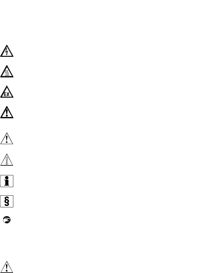
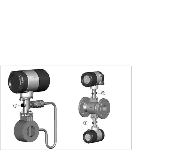
2.2.1 Devices with connection flange
The measuring system consists of a measuring sensor and a signal converter. These elements form a permanent mechanical unit.
Figure 2-2: Flanged devices with display
1Version with temperature sensor
2Version with temperature sensor and optional pressure sensor
3Version with temperature sensor, optional pressure sensor and shut-off valve
4Version flange-sensor with inlet reduction
2.2.2Sandwich version
The sandwich version features 2 centring rings to aid with installation.
Figure 2-3: Sandwich versions with display
1Version with temperature sensor
2Version with temperature sensor and optional pressure sensor
3Version with temperature sensor, optional pressure sensor and shut-off valve
12 |
www.krohne.com |
02/2013 - 4000150606 MA OPTISWIRL4070C R07 en |
|
|
DEVICE DESCRIPTION 2 |
|
OPTISWIRL 4070 |
|
|
|
|
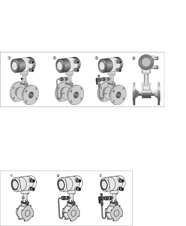
2.2.3 Devices for dual measurement and twofold reliability
This is a genuine redundant system with two independent measuring sensors and two signal converters.
This provides twofold functional reliability and availability of the measurement.
This variant is ideally suited for measurements in multi-product pipelines. In such pipelines, two different products are moved through one after the other.
One signal converter can be programmed for one product, and the other signal converter for the other product.
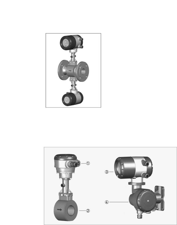
2.2.4 Device version remote
1Sensor terminal box
2Sensor
3Signal converter
4Wall mount bracket connection box
With the remote variant, sensors and converters are separate. The 10-pin, shielded connection cable may not exceed 15m in length.
02/2013 - 4000150606 MA OPTISWIRL4070C R07 en |
www.krohne.com |
13 |
2 DEVICE DESCRIPTION |
|
|
OPTISWIRL 4070 |
|
|
2.2.5 Device description |
|
|
|
|
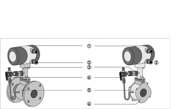
Figure 2-4: Device description
1Signal converter
2Cable feedthrough grey, standard version
3Pressure sensor, optional
4Shut-off valve, optional
5Measuring sensor
6Centering ring
2.2.6Free air delivery measurement - FAD (optional)
A (air) compressor draws air from the ambient atmosphere, compresses it and delivers it at the required pressure. Since the ambient atmosphere also contains water vapour, what the compressor draws in is a mixture of air and water vapour. Free air delivery measurement is to be understood under this condition. Most manufacturers specify free air delivery only at standard intake conditions. What the user ultimately requires as process air must first be determined before measuring can take place with an accuracy of ±1%.
The vortex flowmeter with the optional FAD function can measure the free air delivery online, humidity and speed compensated, regardless of its function as standard flowmeter. The integrated software evaluates the free air delivery automatically online.
The menu-driven, user-friendly software prompts the operator to enter the pressure, relative humidity, the required as well as current discharge pressure.
The steam tables and compressibility tables are saved as standard. The measuring device is optionally available with a pressure sensor which measures the discharge pressure online, making manual input of the values unnecessary.
14 |
www.krohne.com |
02/2013 - 4000150606 MA OPTISWIRL4070C R07 en |

|
|
DEVICE DESCRIPTION 2 |
|
OPTISWIRL 4070 |
|
|
|
|
2.2.7 Gross heat meter
In almost all applications with saturated steam, the steam is used for heating. It is much more interesting to know how great the heat flow volume is that is available to the process, than to know how great the flow is in kg/h.
As the enthalpy of steam changes with the temperature, it cannot be assumed as a constant. The vortex flowmeter has a special feature that can calculate the flow of vapour and water as power output. The enthalpy tables are permanently programmed in the memory of the device.
The online density-compensated mass flow is multiplied by the correct enthalpy to obtain the flow as power output.
Power {QH] = mass flow [Qm] x enthalpy [H]
If the gross heat meter is activated, both the totalizer for the absolute steam consumption as well as that for the energy run internally.
02/2013 - 4000150606 MA OPTISWIRL4070C R07 en |
www.krohne.com |
15 |
2 DEVICE DESCRIPTION |
|
|
OPTISWIRL 4070 |
|
|
|
|
|
2.2.8 Dual seal
To cover the requirements of ANSI/ISA-12.27.01-2003 “Requirements for Process Sealing Between Electrical Systems and Flammable or Combustible Process Fluid” Dual seal, a membrane vent is integrated in the neck of the instrument. This vent works in the improbable case of a leakage as an annunciation valve between the primary seal (Process) and secondary seal (electronic compartment).
1 Annunciation valve (Membrane vent)
The sealing between the pick-up and the Flow tube is considered as the primary seal. Its construction material is always the same as the Flow tube itself (e.g. Stainless steel 316L or Hastelloy C22). Chemicals used for the process, going through the Flow tube, must be compatible with the designated material.
By using the membrane vent as annunciation valve, all requirements for a dual seal device in accordance to above mentioned standard, are fulfilled.
•It protects the electronic compartment against access by process media, due to possible leakages.
•The leakage of the primary seal is visible.
Regular maintenance should be performed by the customer to ensure this Dual Seal notification system is working properly or that there is no leak.
If a leakage is noticed:
The manufacturer service should be contacted for servicing or replacement of the meter.
16 |
www.krohne.com |
02/2013 - 4000150606 MA OPTISWIRL4070C R07 en |

|
|
DEVICE DESCRIPTION 2 |
|
OPTISWIRL 4070 |
|
|
|
|
2.3 Nameplate
INFORMATION!
Look at the device nameplate to ensure that the device is delivered according to your order. Check for the correct supply voltage printed on the nameplate.
Figure 2-5: Example for nameplate
1Device type
2Manufacturer
3Sensor:
S - Sandwich F - Flange
FR - Flange single reduced F2R - Flange double reduced
4Notified ATEX & DGRL bodies (only available if this option was ordered)
5Connection data: nominal diameter and pressure rating
6PED data
7Ex data (only available if this option was ordered)
8Electrical connection data
9Manufacturer's website
Figure 2-6: Example for nameplate
1Serial number
2Order Number
3Type code
4Item number
5Fluid data
6Software variant
7TAG number
02/2013 - 4000150606 MA OPTISWIRL4070C R07 en |
www.krohne.com |
17 |

3 INSTALLATION |
|
|
OPTISWIRL 4070 |
|
|
|
|
|
3.1 Notes on installation
INFORMATION!
Inspect the cartons carefully for damages or signs of rough handling. Report damage to the carrier and to the local office of the manufacturer.
INFORMATION!
Do a check of the packing list to make sure that you have all the elements given in the order.
INFORMATION!
Look at the device nameplate to ensure that the device is delivered according to your order. Check for the correct supply voltage printed on the nameplate.
3.2Storage
•Store the device in a dry and dust-free location.
•Avoid extended direct exposure to the sun.
•Store the device in its original packing.
•The permissible storage temperature for standard devices is -40...+80°C / -40...+176°F.
3.3Transport
•Use lifting straps wrapped around both process connections for transport.
•Do not lift measuring devices by the signal converter housing for transport.
•Never lift the measuring device by the pressure sensor.
•Do not use lifting chains as they may damage the housing.
Figure 3-1: Transport instructions
CAUTION!
Non-secured devices can pose risk of injury. The centre of mass of the device is often higher than the point at which the lifting straps are attached.
Prevent the measuring device from sliding or rotating accidentally.
18 |
www.krohne.com |
02/2013 - 4000150606 MA OPTISWIRL4070C R07 en |

|
|
INSTALLATION 3 |
|
OPTISWIRL 4070 |
|
|
|
|
3.4 Installation conditions
INFORMATION!
For accurate volumetric flow measurement the measuring device needs a completely filled pipe and a fully developed flow profile.
Please observe the instructions regarding inlet and outlet pipe runs as well as the installation position.
In the event of vibrations on the piping, select the installation site so that the vibrations are at their lowest in a transverse direction to the flowmeter.
CAUTION!
When installing the device in the piping, the following points must be observed:
•Nominal diameter of connection pipe flange = nominal flange diameter of pipe!
•Use flanges with smooth holes, e.g. welding neck flanges.
•Align carefully the holes of the connecting flange and the flowmeter flange.
•Check the compatibility of the gasket material with the process product.
•Make sure that the gaskets are arranged concentrically. The flange gaskets must not project into the pipe cross-section.
•The flanges have to be concentric.
•There must not be any pipe bends, valves, flaps or other internals in the immediate inlet run.
•Devices in sandwich version may only be installed using a centering ring.
•Never install the device directly behind piston compressors or rotary piston meters.
•Do not lay signal cables directly next to cables for the power supply.
INFORMATION!
If the danger of waterhammers can occur in steam networks appropriate condensate separators have to be installed.
Suitable measures must be taken to avoid water cavitation if it is a possible risk.
02/2013 - 4000150606 MA OPTISWIRL4070C R07 en |
www.krohne.com |
19 |
3 INSTALLATION |
|
|
OPTISWIRL 4070 |
|
|
|
|
|
3.4.1 Measurement of liquids
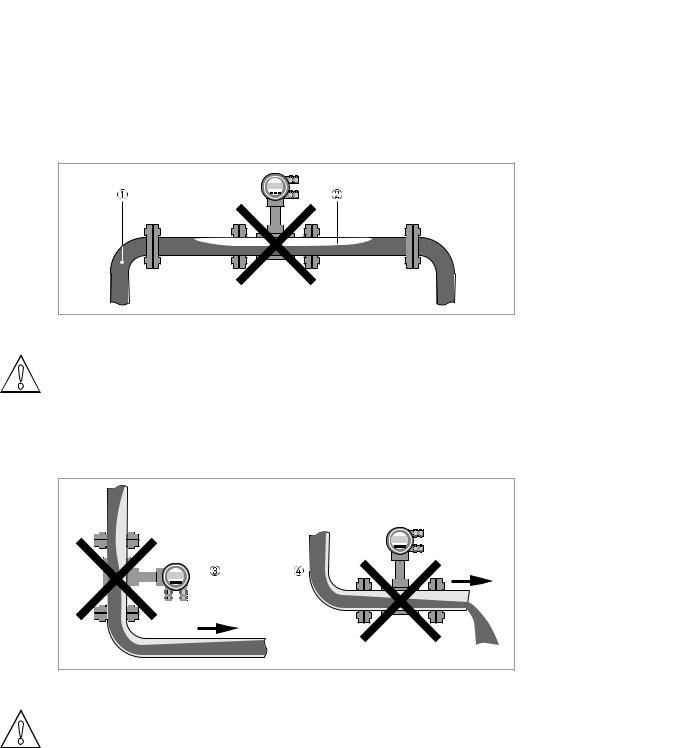
Prohibited installation
Figure 3-2: Upper pipe bend
CAUTION!
Prohibited: Installing the device in an upper pipe bend 1, because there is a risk of gas bubbles 2 forming. Gas bubbles can lead to pressure surges and inaccurate measurement.
Figure 3-3: Downpipe and outlet
CAUTION!
Prohibited: Installing the device in a downstream pipe 3 or upstream pipe of a outlet 4. There is the risk of partially filled pipes.
20 |
www.krohne.com |
02/2013 - 4000150606 MA OPTISWIRL4070C R07 en |
|
|
INSTALLATION 3 |
|
OPTISWIRL 4070 |
|
|
|
|
Recommended installations for measurement of liquids
CAUTION!
It is absolutely necessary to comply with the required inlet and outlet runs.
1If the device is installed in a downpipe, a standpipe must be installed immediately after it.
2Installing the device in an inclined standpipe.
3Installing the device in a vertical standpipe.
4Installing the device in the lower pipe bend.
1Above a horizontal pipe
2On a vertical pipe
INFORMATION!
Depending on the installation position, you may have to rotate the display and/or the connection housing.
02/2013 - 4000150606 MA OPTISWIRL4070C R07 en |
www.krohne.com |
21 |
3 INSTALLATION |
|
|
OPTISWIRL 4070 |
|
|
|
|
|
3.4.2 Measurement of vapours and gases
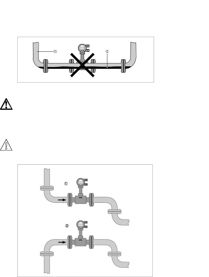
Prohibited installation
1Lower pipe bends
2Condensate
DANGER!
Prohibited: Installing the device in a lower pipe bend 1, because there is a risk of condensate forming 2.
Condensate can lead to cavitation and inaccurate measurement. Under certain circumstances the device can be destroyed and the measured product can leak.
Recommended installations
CAUTION!
It is absolutely necessary to maintain the required inlet and outlet runs.
1Inlet and outlet falling
2Rising inlet - falling outlet
22 |
www.krohne.com |
02/2013 - 4000150606 MA OPTISWIRL4070C R07 en |
|
|
INSTALLATION 3 |
|
OPTISWIRL 4070 |
|
|
|
|
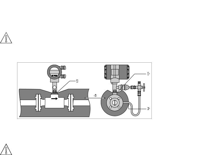
3.4.3 Pipelines with control valve
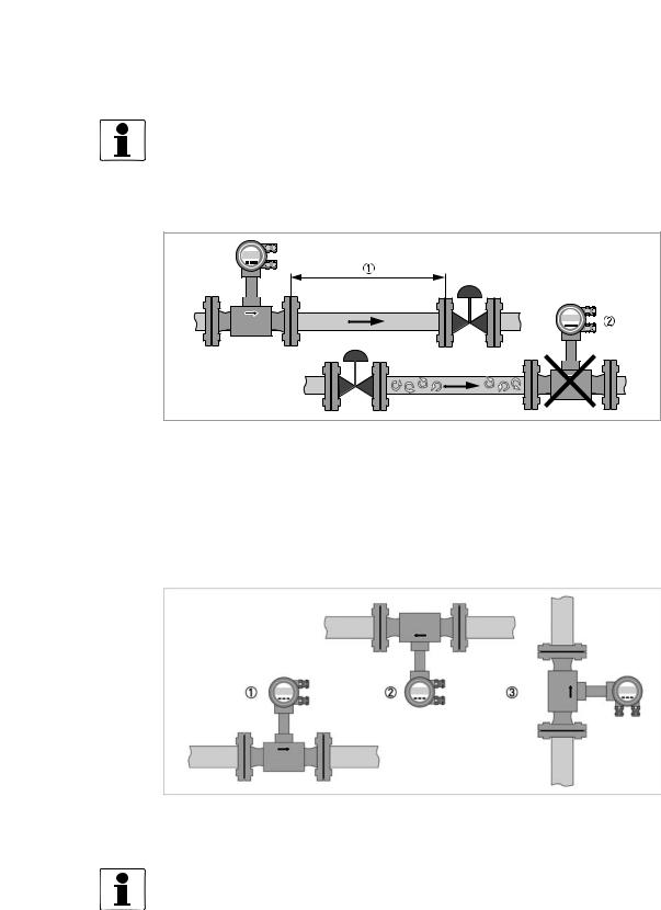
INFORMATION!
To ensure smooth and correct measurement, the manufacturer recommends not installing the measuring device downstream from a control valve. This would run the risk of vortex formation, which would distort the measuring result.
Figure 3-4: Pipeline with control valve
1Recommended: installing the device upstream from the control valve at a distance of ≥ 5 DN
2Not recommended: Installing the flowmeter directly downstream of control valves, due to vortex formation.
3.4.4Preferred mounting position
Preferred mounting position
1Above a horizontal pipe
2underneath a horizontal pipe (not permitted with lines at risk for condensate)
3On a vertical pipe
INFORMATION!
Depending on the installation position, you may have to rotate the display and/or the connection housing. For further information refer to Turning the display on page 25.
02/2013 - 4000150606 MA OPTISWIRL4070C R07 en |
www.krohne.com |
23 |
3 INSTALLATION |
|
|
OPTISWIRL 4070 |
|
|
|
|
|
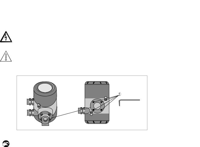
3.4.5 Turning the connection housing
DANGER!
All work on the device electrics may only be carried out by appropriately trained personnel. The regional occupational health and safety directives must always be observed.
CAUTION!
Do not damage the electrical cable by overtwisting it.
Do not remove the electrical connector.
Figure 3-5: Allen screws on connection housing
• Disconnect the power supply from the measuring device.
•Loosen the four screws 1 on the rear side of the connection housing.
•Lift the connection housing and turn it to the required position in 90° steps.
•Screw the connection housing back on.
24 |
www.krohne.com |
02/2013 - 4000150606 MA OPTISWIRL4070C R07 en |
|
|
INSTALLATION 3 |
|
OPTISWIRL 4070 |
|
|
|
|
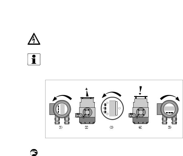
3.4.6 Turning the display
DANGER!
All work on the device electrics may only be carried out by appropriately trained personnel. The regional occupational health and safety directives must always be observed.
INFORMATION!
If the measuring device is installed in a vertical pipe, you will have to turn the display by 90°; if installed below a pipe, turn 180°.
Figure 3-6: Turning the display
Turn the display as follows:
•Disconnect the power supply from the measuring device.
•Unscrew the cover in front of the display 1 from the connection housing.
•Pull the display 2 carefully a few centimetres out of the anchor fitting and turn it to the required position 3.
•Press the display onto the spacer pins 4, until it clicks.
•Turn the cover with gasket 5 back onto the housing and tighten it by hand.
02/2013 - 4000150606 MA OPTISWIRL4070C R07 en |
www.krohne.com |
25 |
3 INSTALLATION |
|
|
OPTISWIRL 4070 |
|
|
|
|
|
3.4.7 Heat insulation
CAUTION!
The area above the converter support must not be heat-insulated.
The heat insulation 3 may only extend to the maximum height 1 shown below up to the connecting screws of the measuring sensor.
Figure 3-7: Heat insulation on connection piece and signal cable
1Max. height of insulation up to intermediate piece between measuring sensor and signal converter
2Max. thickness of the insulation up to the bend of the pressure pipe
3Insulation
CAUTION!
The heat insulation 3 may only extend as far as the bend of the pressure sensing line 2.
26 |
www.krohne.com |
02/2013 - 4000150606 MA OPTISWIRL4070C R07 en |
 Loading...