


 OPTIWAVE 7500 C Handbook
80 GHz Radar (FMCW) Level Transmitter for liquids in narrow tanks with internal obstructions
© KROHNE 04/2017 - 4004375401 - MA OPTIWAVE 7500 R01 en
:IMPRINT :::::::::::::::::::::::::::::::::::::::
All rights reserved. It is prohibited to reproduce this documentation, or any part thereof, without the prior written authorisation of KROHNE Messtechnik GmbH.
Subject to change without notice.
Copyright 2017 by
KROHNE Messtechnik GmbH - Ludwig-Krohne-Str. 5 - 47058 Duisburg (Germany)
2 |
www.krohne.com |
04/2017 - 4004375401 - MA OPTIWAVE 7500 R01 en |

|
|
|
CONTENTS |
|
|
|
|
OPTIWAVE 7500 C |
|
||||
|
|
1 Safety instructions |
6 |
|
||
|
|
|
||||
|
|
|
|
|
||
1.1 |
Software history ............................................................................................................... |
6 |
||||
1.2 |
Intended use ..................................................................................................................... |
6 |
||||
1.3 |
Certification ...................................................................................................................... |
7 |
||||
1.4 |
Electromagnetic compatibility ......................................................................................... |
7 |
|
|||
1.5 |
Radio approvals ................................................................................................................ |
8 |
||||
1.5.1 European Union (EU)............................................................................................................... |
8 |
|
1.5.2 U.S.A...................................................................................................................................... |
10 |
|
1.5.3 Canada................................................................................................................................... |
12 |
|
1.6 |
Safety instructions from the manufacturer ................................................................... |
14 |
1.6.1 Copyright and data protection .............................................................................................. |
14 |
|
1.6.2 Disclaimer ............................................................................................................................. |
14 |
|
1.6.3 Product liability and warranty .............................................................................................. |
15 |
|
1.6.4 Information concerning the documentation......................................................................... |
15 |
|
1.6.5 Warnings and symbols used................................................................................................. |
16 |
|
1.7 |
Safety instructions for the operator............................................................................... |
16 |
2 Device description |
17 |
|
|
|
|
2.1 |
Scope of delivery............................................................................................................. |
17 |
2.2 |
Device description .......................................................................................................... |
18 |
2.3 |
Visual Check ................................................................................................................... |
19 |
2.4 |
Nameplates .................................................................................................................... |
20 |
2.4.1 Nameplate (examples).......................................................................................................... |
20 |
|
3 Installation |
21 |
|
|
|
|
3.1 |
General notes on installation ......................................................................................... |
21 |
3.2 |
Storage ........................................................................................................................... |
21 |
3.3 |
Transport ........................................................................................................................ |
22 |
3.4 |
Pre-installation requirements ....................................................................................... |
22 |
3.5 |
Pressure and temperature ranges ................................................................................ |
23 |
3.6 |
Recommended mounting position ................................................................................. |
24 |
3.6.1 General notes........................................................................................................................ |
24 |
|
3.6.2 Tanks with dish-shaped and conical bottoms...................................................................... |
26 |
|
3.7 |
Mounting restrictions ..................................................................................................... |
27 |
3.7.1 General notes........................................................................................................................ |
27 |
|
3.7.2 Process connections............................................................................................................. |
29 |
|
3.7.3 LPR devices: recommendations for pits and tanks made of non-conductive materials .... |
31 |
|
3.8 |
How to turn or remove the display module (option) ...................................................... |
33 |
3.9 |
Weather protection......................................................................................................... |
34 |
3.9.1 How to attach the weather protection to the device............................................................. |
34 |
|
3.9.2 How to open the weather protection .................................................................................... |
36 |
|
4 Electrical connections |
37 |
|
|
|
|
4.1 |
Safety instructions.......................................................................................................... |
37 |
4.2 |
Electrical installation: 2-wire, loop-powered ................................................................ |
37 |
4.3 |
Electrical connection for current output ....................................................................... |
41 |
04/2017 - 4004375401 - MA OPTIWAVE 7500 R01 en |
www.krohne.com |
3 |

|
CONTENTS |
OPTIWAVE 7500 C |
|
|
|
||
|
|
|
|
4.3.1 Non-Ex devices ..................................................................................................................... |
41 |
|
4.3.2 Devices for hazardous locations........................................................................................... |
41 |
|
4.4 |
Ingress protection .......................................................................................................... |
41 |
4.5 |
Networks ........................................................................................................................ |
42 |
4.5.1 General information.............................................................................................................. |
42 |
|
4.5.2 Point-to-point connection..................................................................................................... |
42 |
|
4.5.3 Multi-drop networks ............................................................................................................. |
43 |
|
5 Start-up |
44 |
|
5.1 |
Start-up checklist........................................................................................................... |
44 |
5.2 |
How to start the device................................................................................................... |
44 |
5.3 |
Operating concept .......................................................................................................... |
44 |
5.4 |
Digital display screen ..................................................................................................... |
45 |
5.4.1 Display screen layout............................................................................................................ |
45 |
|
5.4.2 Keypad buttons ..................................................................................................................... |
46 |
|
5.5 |
Remote communication with PACTware™ .................................................................... |
48 |
5.6 |
Remote communication with the AMS™ Device Manager............................................. |
49 |
6 Operation |
50 |
|
6.1 |
User modes .................................................................................................................... |
50 |
6.2 |
Normal mode.................................................................................................................. |
50 |
6.3 |
Program mode................................................................................................................ |
53 |
6.3.1 General notes........................................................................................................................ |
53 |
|
6.3.2 Protection of the device settings (access levels) ................................................................. |
54 |
|
6.3.3 How to get access to the Quick Setup menu ........................................................................ |
56 |
|
6.3.4 Keypad functions................................................................................................................... |
57 |
|
6.3.5 How to save settings changed in Program mode................................................................. |
60 |
|
6.3.6 Menu overview ...................................................................................................................... |
61 |
|
6.3.7 Function description ............................................................................................................. |
66 |
|
6.4 |
Further information on device configuration in Program mode ................................... |
86 |
6.4.1 Standard setup...................................................................................................................... |
86 |
|
6.4.2 Empty spectrum recording ................................................................................................... |
89 |
|
6.4.3 HART® network configuration ............................................................................................. |
92 |
|
6.4.4 Distance measurement ........................................................................................................ |
93 |
|
6.4.5 Level measurement .............................................................................................................. |
94 |
|
6.4.6 How to configure the device to measure volume or mass................................................... |
96 |
|
6.4.7 How to measure correctly in tanks with curved or conical bottoms ................................... |
98 |
|
6.4.8 How to make a filter to remove radar signal interference .................................................. |
99 |
|
6.5 |
Status messages and diagnostic data.......................................................................... |
100 |
7 Service |
107 |
|
7.1 |
Periodic maintenance................................................................................................... |
107 |
7.1.1 General notes...................................................................................................................... |
107 |
|
7.1.2 Maintenance of the O-rings for the housing covers........................................................... |
107 |
|
7.1.3 How to clean the top surface of the device......................................................................... |
108 |
|
7.2 |
Service warranty........................................................................................................... |
108 |
7.3 |
Spare parts availability................................................................................................. |
108 |
7.4 |
Availability of services .................................................................................................. |
108 |
4 |
www.krohne.com |
04/2017 - 4004375401 - MA OPTIWAVE 7500 R01 en |

|
|
CONTENTS |
|
|
OPTIWAVE 7500 C |
|
|
|
|
|
|
7.5 |
Returning the device to the manufacturer................................................................... |
109 |
7.5.1 General information............................................................................................................ |
109 |
|
7.5.2 Form (for copying) to accompany a returned device.......................................................... |
110 |
|
7.6 |
Disposal ........................................................................................................................ |
110 |
8 Technical data |
111 |
|
8.1 |
Measuring principle...................................................................................................... |
111 |
8.2 |
Technical data............................................................................................................... |
113 |
8.3 |
Minimum power supply voltage ................................................................................... |
118 |
8.4 |
Measuring accuracy ..................................................................................................... |
119 |
8.5 |
Guidelines for maximum operating pressure.............................................................. |
123 |
8.6 |
Dimensions and weights .............................................................................................. |
125 |
9 Description of HART interface |
131 |
|
9.1 |
General description ...................................................................................................... |
131 |
9.2 |
Software history ........................................................................................................... |
132 |
9.3 |
Connection variants...................................................................................................... |
132 |
9.3.1 Point-to-Point connection – analogue / digital mode ........................................................ |
132 |
|
9.3.2 Multi-Drop connection (2-wire connection) ....................................................................... |
133 |
|
9.4 |
HART® device variables............................................................................................... |
133 |
9.5 |
Field Communicator 475 (FC 475)................................................................................ |
133 |
9.5.1 Installation .......................................................................................................................... |
133 |
|
9.5.2 Operation............................................................................................................................. |
134 |
|
9.6 |
Asset Management Solutions (AMS®) ......................................................................... |
134 |
9.6.1 Installation .......................................................................................................................... |
134 |
|
9.6.2 Operation............................................................................................................................. |
134 |
|
9.6.3 Parameter for the basic configuration ............................................................................... |
134 |
|
9.7 |
Field Device Tool / Device Type Manager (FDT / DTM)................................................ |
135 |
9.7.1 Installation .......................................................................................................................... |
135 |
|
9.7.2 Operation............................................................................................................................. |
135 |
|
9.8 |
Process Device Manager (PDM)................................................................................... |
135 |
9.8.1 Installation .......................................................................................................................... |
135 |
|
9.8.2 Operation............................................................................................................................. |
135 |
|
9.9 |
HART® menu tree for AMS .......................................................................................... |
136 |
9.9.1 Overview AMS menu tree (positions in menu tree)............................................................ |
136 |
|
9.9.2 AMS menu tree (details for settings).................................................................................. |
137 |
|
9.10 HART® menu tree for PDM........................................................................................ |
140 |
|
9.10.1 Overview PDM menu tree (positions in menu tree).......................................................... |
140 |
|
9.10.2 PDM menu tree (details for settings) ............................................................................... |
141 |
|
10 Appendix |
144 |
|
10.1 Order code .................................................................................................................. |
144 |
|
10.2 Spare parts ................................................................................................................. |
148 |
|
10.3 Accessories................................................................................................................. |
151 |
|
10.4 Glossary ...................................................................................................................... |
152 |
|
11 Notes |
155 |
|
04/2017 - 4004375401 - MA OPTIWAVE 7500 R01 en |
www.krohne.com |
5 |

1 SAFETY INSTRUCTIONS |
|
|
OPTIWAVE 7500 C |
|
|
|
|
|
1.1 Software history
"Firmware revision" agrees with NAMUR NE 53. It is a series of numbers used to record the revision status of embedded software (firmware) in electronic equipment assemblies. It gives data on the type of changes made and the effect that changes have on compatibility.
Data about software revisions is shown in menu 1.1.0 IDENT. For more data, refer to Function description on page 66. If it is not possible to refer to the device menu, record the serial number of the device (given on the device nameplate) and speak to the supplier.
Changes and effect on compatibility
1 |
Downwards compatible changes and fault repair with no effect on operation (e.g. spelling |
|
|
mistakes on display) |
|
|
|
|
2-_ |
Downwards compatible hardware and/or software change of interfaces: |
|
|
|
|
|
H |
HART® |
|
P |
Profibus |
|
|
|
|
F |
FOUNDATION fieldbus |
|
|
|
3-_ |
Downwards compatible hardware and/or software change of inputs and outputs: |
|
|
|
|
|
CO |
Current output |
|
|
|
|
FO, |
Frequency output / pulse output |
|
PO |
|
|
|
|
|
SO |
Status output |
|
|
|
|
LS |
Limit switch |
|
|
|
|
CI |
Current input |
|
|
|
|
D |
Display |
|
|
|
Release |
Printed circuit |
Firmware |
Electronic |
Hardware |
Changes and |
Documentation |
date |
assembly |
revision |
revision |
revision |
compatibility |
|
|
|
|
|
|
|
|
2017-02-02 |
HMI (LCD display |
BL1.24.04 |
ER1.0.06 |
4002905801a |
— |
HB OPTIWAVE |
|
option) |
|
|
1 |
|
7500 R01 |
|
Main and Support |
|
|
4002815701d |
|
|
|
|
|
|
|
|
|
|
Sensor |
|
|
4004742601a |
|
|
|
|
|
|
|
|
|
1 If the device does not have the display module option, the module reference number is 4002905802a
1.2 Intended use
CAUTION!
Responsibility for the use of the measuring devices with regard to suitability, intended use and corrosion resistance of the used materials against the measured fluid lies solely with the operator.
INFORMATION!
The manufacturer is not liable for any damage resulting from improper use or use for other than the intended purpose.
This radar level transmitter measures distance, level, mass, volume and reflectivity of liquids, pastes and slurries.
It can be installed on tanks, reactors and open channels.
6 |
www.krohne.com |
04/2017 - 4004375401 - MA OPTIWAVE 7500 R01 en |
OPTIWAVE 7500 C
SAFETY INSTRUCTIONS 1
1.3 Certification
DANGER!
For devices used in hazardous areas, additional safety notes apply; please refer to the Ex documentation.
CE marking
The device meets the essential requirements of the EU Directives:
•Electromagnetic Compatibility (EMC) directive
•The safety part of the Low-Voltage directive
•For devices used in hazardous locations: ATEX directive
The manufacturer certifies successful testing of the product by applying the CE marking. For more data about the EU Directives and European Standards related to this device, refer to the EU Declaration of Conformity. You can find this documentation on the DVD-ROM supplied with the device or it can be downloaded free of charge from the website (Download Center).
All devices are based on the CE marking and meet the requirements of NAMUR
Recommendations NE 21, NE 43, NE 53 and NE 107.
1.4 Electromagnetic compatibility
The device agrees with the Electromagnetic Compatibility Directive.
You can install the device on tanks, open vessels or channels, but the type of antenna must agree with the location of the device. For more data, refer to Radio approvals on page 8.
INFORMATION!
This agrees with Immunity and Emissions requirements for industrial environments.
04/2017 - 4004375401 - MA OPTIWAVE 7500 R01 en |
www.krohne.com |
7 |
1 SAFETY INSTRUCTIONS
1.5 Radio approvals
1.5.1 European Union (EU)
OPTIWAVE 7500 C 
INFORMATION!
LPR (Level Probing Radar) devices measure level in the open air or in a closed space (a metallic tank etc.). TLPR (Tank Level Probing Radar) devices measure level in a closed space only. You can use LPR devices for TLPR applications. The LPR and TLPR devices meet the requirements of the RED (Radio Equipment Directive) for use in the member countries of the EU.
For more data about the order code, refer to Order code on page 144.
This level transmitter is approved to be used outside metallic tanks. If you use the device in the open air, read the device nameplate to make sure that the device can be used for your application. Refer also to the table that follows:
Antenna type |
Order code |
|
Permitted for: |
|||||
|
|
|
|
|
|
|
|
|
PEEK / DN20 (¾¨) Lens |
VFDFxxxxxxxxxxxxx1xx... |
|
TLPR |
|||||
|
|
|
|
|
|
|
|
|
PEEK / DN25 (1¨) Lens |
VFDFxxxxxxxxxxxxx2xx... |
|
TLPR |
|||||
|
|
|
|
|
|
|
|
|
PEEK / DN40 (1½¨) Lens |
VFDFxxxxxxxxxxxxx3xx... |
|
LPR + TLPR |
|||||
|
|
|
|
|
|
|
|
|
PEEK / DN70 (2¾¨) Lens |
VFDFxxxxxxxxxxxxx4xx... |
|
LPR + TLPR |
|||||
|
|
|
|
|
|
|
|
|
|
|
|
|
|
|
|
|
|
|
|
|
|
|
|
|
|
|
|
|
|
|
|
|
|
|
|
|
|
|
|
|
|
|
|
|
|
|
|
|
|
|
|
|
|
|
|
|
|
|
|
|
|
|
|
|
|
|
|
|
|
|
|
|
|
|
|
|
|
|
|
|
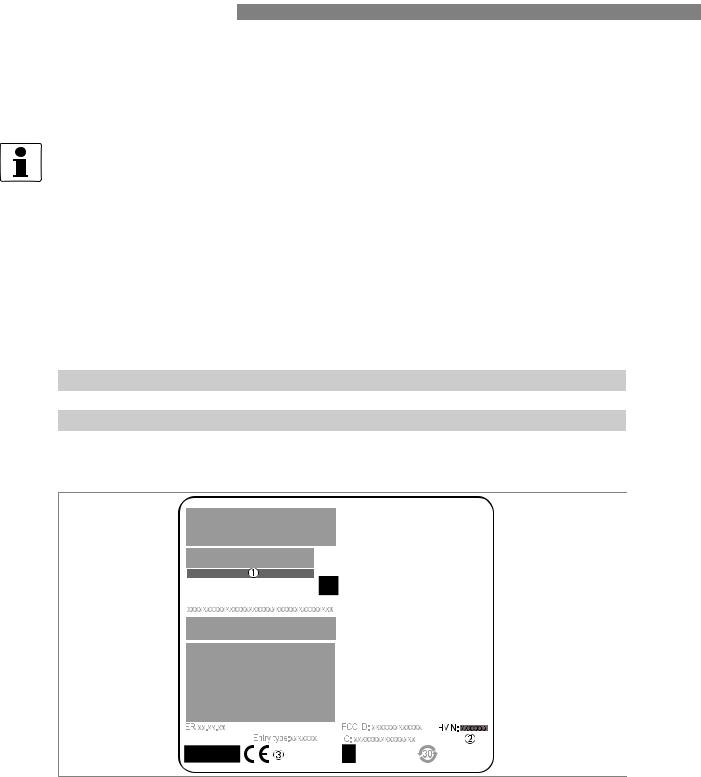
Figure 1-1: European Union: radio approval information on the nameplate
1Type code (defined in order). For more data, refer to Order code on page 144.
2HVIN (Hardware Version Identification Number). This number gives the radar signal frequency (80G = 80 GHz), the location of the device (T=TLPR or L=LPR) and the type of signal converter (compact (C))
TLPR device: HVIN: 80G-T-C LPR device: HVIN: 80G-L-C
3CE sign
8 |
www.krohne.com |
04/2017 - 4004375401 - MA OPTIWAVE 7500 R01 en |
OPTIWAVE 7500 C
SAFETY INSTRUCTIONS 1
TLPR (Tank Level Probing Radar) devices only
Use approved personnel to install the device. The device and the tank agree with the RED (Radio Equipment Directive) if you obey the instructions that follow:
•TLPR (Tank Level Probing Radar) are required to be installed at a permanent fixed position at a closed (not open) metallic tank or reinforced concrete tank, or similar enclosure structure made of comparable attenuating material;
•flanges and attachments of the TLPR equipment shall provide the necessary microwave sealing by design;
•sight glasses shall be coated with a microwave-proof coating when necessary (i.e. electrically conductive coating);
•manholes or connection flanges at the tank shall be closed to ensure a low-level leakage of the signal into the air outside the tank;
•whenever possible, mounting of the TLPR equipment shall be on top of the tank structure with the orientation of the antenna to point in a downward direction;
•installation and maintenance of the TLPR equipment shall be performed by professionally trained individuals only.
For data about how to install EMI/RFI shielding gaskets, refer to the instructions supplied with this accessory.
LPR (Level Probing Radar) devices only
Use approved personnel to install the device. If the device is operated in the open air (outdoors), it agrees with the RED (Radio Equipment Directive) if you obey these instructions:
• The antenna must always point downwards. The boresight direction of the antenna must be vertical. No other angles are permitted.
•Install the device more than 4 km / 2.485 mi away from radio astronomy sites.
•If the device is 4...40 km / 2.485...24.855 mi away from radio astronomy sites, do not install the device more than 15 m / 49.21 ft above the ground.
CAUTION!
If it is necessary to install the device less than 4 km / 2.485 mi from radio astronomy sites, you must get the approval of the national regulatory authority before installation (e.g. ANFR (France), Bundesnetzagentur (Germany), Ofcom (United Kingdom) etc.).
Radio quiet zones: locations of radio astronomy sites (stations) in Europe and northern Eurasia
Country |
Name of the station |
|
Location |
|
|
|
|
|
|
|
|
Latitude, ϕ |
|
Longitude, λ |
|
|
|
|
|
Finland |
Metsähovi |
60°13'04" N |
|
24°23'37" E |
|
|
|
|
|
France |
Plateau de Bure |
44°38'01" N |
|
05°54'26" E |
|
|
|
|
|
Germany |
Effelsberg |
50°31'32" N |
|
06°53'00" E |
|
|
|
|
|
Italy |
Sardinia |
39°29'50" N |
|
09°14'40" E |
|
|
|
|
|
Spain |
Yebes |
40°31'27" N |
|
03°05'22" W |
|
|
|
|
|
|
Pico Veleta |
37°03'58" N |
|
03°23'34" W |
Sweden |
Onsala |
57°23’45" N |
|
11°55’35" E |
04/2017 - 4004375401 - MA OPTIWAVE 7500 R01 en |
www.krohne.com |
9 |

1 SAFETY INSTRUCTIONS
1.5.2 U.S.A.
OPTIWAVE 7500 C 
INFORMATION!
LPR (Level Probing Radar) devices measurement level in the open air or in a closed space (a metallic tank etc.). TLPR (Tank Level Probing Radar) devices measure of level in a closed space only.
This level transmitter is approved to be used outside metallic tanks. If you use the device in the open air, read the device nameplate to make sure that the device can be used for your application. Refer also to the table that follows:
Antenna type |
Order code |
Permitted for: |
|
|
|
PEEK / DN20 (¾¨) Lens |
VFDFxxxxxxxxxxxxx1xx... |
TLPR |
|
|
|
PEEK / DN25 (1¨) Lens |
VFDFxxxxxxxxxxxxx2xx... |
TLPR |
|
|
|
PEEK / DN40 (1½¨) Lens |
VFDFxxxxxxxxxxxxx3xx... |
LPR + TLPR |
|
|
|
PEEK / DN70 (2¾¨) Lens |
VFDFxxxxxxxxxxxxx4xx... |
LPR + TLPR |
|
|
|
LEGAL NOTICE!
This device complies with Part 15 of the FCC Rules. Operation is subject to the following two conditions:
1.This device may not cause harmful interference, and
2.This device must accept any interference received, including interference which may cause undesired operation.
Changes or modifications made to this equipment not expressly approved by the manufacturer may void the FCC authorizations to operate this equipment.
This equipment has been tested and found to comply with the limits for a Class B digital device, pursuant to Part 15 of the FCC Rules. These limits are designed to provide reasonable protection against harmful interference in a residential installation. This equipment generates, uses and can radiate radio frequency energy and, if not installed and used in accordance with the instructions, may cause harmful interference to radio communications. However, there is no guarantee that interference will not occur in a particular installation. If this equipment does cause harmful interference to radio or television reception, which can be determined by turning the equipment off and on, the user is encouraged to try to correct the interference by one or more of the following measures:
•Reorient or relocate the receiving antenna.
•Increase the separation between the equipment and receiver.
•Connect the equipment into an outlet on a circuit different from that to which the receiver is connected.
•Consult the dealer or an experienced radio/TV technician for help.
The Product Marketing Name (PMN) of this device is "Optiwave x500 series".
10 |
www.krohne.com |
04/2017 - 4004375401 - MA OPTIWAVE 7500 R01 en |
OPTIWAVE 7500 C
SAFETY INSTRUCTIONS 1
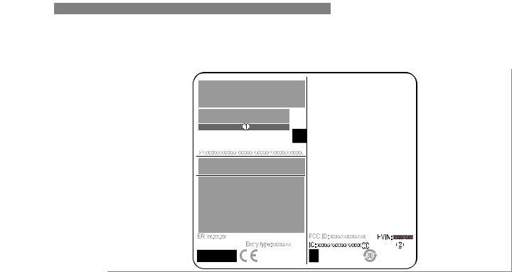
Figure 1-2: U.S.A.: radio approval information on the nameplate
1Type code (defined in order). For more data, refer to Order code on page 144.
2HVIN (Hardware Version Identification Number). This number gives the radar signal frequency (80G = 80 GHz), the location of the device (T=TLPR or L=LPR) and the type of signal converter (compact (C))
TLPR device: HVIN: 80G-T-C LPR device: HVIN: 80G-L-C
3FCC ID
TLPR device: FCC-ID: Q6BFMCW80G74TA LPR device: FCC-ID: Q6BFMCW80G74LA
04/2017 - 4004375401 - MA OPTIWAVE 7500 R01 en |
www.krohne.com |
11 |

1 SAFETY INSTRUCTIONS
1.5.3 Canada
OPTIWAVE 7500 C 
INFORMATION!
LPR (Level Probing Radar) devices measure level in the open air or in a closed space (a metallic tank etc.). TLPR (Tank Level Probing Radar) devices measure level in a closed space only.
This level transmitter is approved to be used outside metallic tanks. If you use the device in the open air, read the device nameplate to make sure that the device can be used for your application. Refer also to the table that follows:
Antenna type |
Order code |
Permitted for: |
|
|
|
PEEK / DN20 (¾¨) Lens |
VFDFxxxxxxxxxxxxx1xx... |
TLPR |
|
|
|
PEEK / DN25 (1¨) Lens |
VFDFxxxxxxxxxxxxx2xx... |
TLPR |
|
|
|
PEEK / DN40 (1½¨) Lens |
VFDFxxxxxxxxxxxxx3xx... |
LPR + TLPR |
|
|
|
PEEK / DN70 (2¾¨) Lens |
VFDFxxxxxxxxxxxxx4xx... |
LPR + TLPR |
|
|
|
LEGAL NOTICE!
This device complies with Industry Canada licence-exempt RSS standard(s). Operation is subject to the following conditions:
1.this device may not cause harmful interference, and
2.this device must accept any interference received, including interference that may cause undesired operation.
This device and the handbook complies with the requirements of RSS-Gen. Operation is subject to the conditions that follow:
1.The installation of the LPR/TLPR device shall be done by trained installers, in strict compliance with the manufacturer’s instructions.
2.The use of this device is on a "no-interference, no-protection" basis. That is, the user shall accept operations of high-powered radar in the same frequency band which may interfere with or damage this device. However, devices found to interfere with primary licensing operations will be required to be removed at the user’s expense.
3.The TLPR device shall be installed and operated in a completely enclosed container to prevent RF emissions, which can otherwise interfere with aeronautical navigation.
4.LPR devices: Ensure a vertically downward orientation of the transmit antenna and an installation only at fixed locations.
5.The installer / user of this device shall ensure that it is at least 10 km from the Dominion Radio Astrophysical Observatory (DRAO) near Penticton, British Columbia. The coordinates of the DRAO are latitude 49°19'15" N and longitude 119°37'12" W. For devices not meeting this 10 km separation (e.g. those in the Okanagan Valley, British Columbia) the installer / user must coordinate with, and obtain the written concurrence of, the Director of the DRAO before the equipment can be installed or operated. The Director of the DRAO may be contacted at 250-497-2300 (tel.) or 250-497-2355 (fax). Alternatively, the Manager, Regulatory Standards, Industry Canada, may be contacted.
The Product Marketing Name (PMN) of this device is "Optiwave x500 series".
12 |
www.krohne.com |
04/2017 - 4004375401 - MA OPTIWAVE 7500 R01 en |
OPTIWAVE 7500 C
SAFETY INSTRUCTIONS 1
Figure 1-3: Canada: radio approval information on the nameplate
1Type code (defined in order). For more data, refer to Order code on page 144.
2HVIN (Hardware Version Identification Number). This number gives the radar signal frequency (80G = 80 GHz), the location of the device (T=TLPR or L=LPR) and the type of signal converter (compact (C))
TLPR device: HVIN: 80G-T-C LPR device: HVIN: 80G-L-C
3IC number
TLPR device: 1991D-FMCW80G74TA LPR device: 1991D-FMCW80G74LA
04/2017 - 4004375401 - MA OPTIWAVE 7500 R01 en |
www.krohne.com |
13 |

1 SAFETY INSTRUCTIONS |
|
|
OPTIWAVE 7500 C |
|
|
|
|
|
1.6 Safety instructions from the manufacturer
1.6.1 Copyright and data protection
The contents of this document have been created with great care. Nevertheless, we provide no guarantee that the contents are correct, complete or up-to-date.
The contents and works in this document are subject to copyright. Contributions from third parties are identified as such. Reproduction, processing, dissemination and any type of use beyond what is permitted under copyright requires written authorisation from the respective author and/or the manufacturer.
The manufacturer tries always to observe the copyrights of others, and to draw on works created in-house or works in the public domain.
The collection of personal data (such as names, street addresses or e-mail addresses) in the manufacturer's documents is always on a voluntary basis whenever possible. Whenever feasible, it is always possible to make use of the offerings and services without providing any personal data.
We draw your attention to the fact that data transmission over the Internet (e.g. when communicating by e-mail) may involve gaps in security. It is not possible to protect such data completely against access by third parties.
We hereby expressly prohibit the use of the contact data published as part of our duty to publish an imprint for the purpose of sending us any advertising or informational materials that we have not expressly requested.
1.6.2 Disclaimer
The manufacturer will not be liable for any damage of any kind by using its product, including, but not limited to direct, indirect or incidental and consequential damages.
This disclaimer does not apply in case the manufacturer has acted on purpose or with gross negligence. In the event any applicable law does not allow such limitations on implied warranties or the exclusion of limitation of certain damages, you may, if such law applies to you, not be subject to some or all of the above disclaimer, exclusions or limitations.
Any product purchased from the manufacturer is warranted in accordance with the relevant product documentation and our Terms and Conditions of Sale.
The manufacturer reserves the right to alter the content of its documents, including this disclaimer in any way, at any time, for any reason, without prior notification, and will not be liable in any way for possible consequences of such changes.
14 |
www.krohne.com |
04/2017 - 4004375401 - MA OPTIWAVE 7500 R01 en |

OPTIWAVE 7500 C
SAFETY INSTRUCTIONS 1
1.6.3 Product liability and warranty
The operator shall bear responsibility for the suitability of the device for the specific purpose. The manufacturer accepts no liability for the consequences of misuse by the operator. Improper installation or operation of the devices (systems) will cause the warranty to be void. The respective "Standard Terms and Conditions" which form the basis for the sales contract shall also apply.
1.6.4 Information concerning the documentation
To prevent any injury to the user or damage to the device it is essential that you read the information in this document and observe applicable national standards, safety requirements and accident prevention regulations.
If this document is not in your native language and if you have any problems understanding the text, we advise you to contact your local office for assistance. The manufacturer can not accept responsibility for any damage or injury caused by misunderstanding of the information in this document.
This document is provided to help you establish operating conditions, which will permit safe and efficient use of this device. Special considerations and precautions are also described in the document, which appear in the form of icons as shown below.
04/2017 - 4004375401 - MA OPTIWAVE 7500 R01 en |
www.krohne.com |
15 |
1 SAFETY INSTRUCTIONS |
|
|
OPTIWAVE 7500 C |
|
|
|
|
|
1.6.5 Warnings and symbols used
Safety warnings are indicated by the following symbols.
DANGER!
This warning refers to the immediate danger when working with electricity.
DANGER!
This warning refers to the immediate danger of burns caused by heat or hot surfaces.
DANGER!
This warning refers to the immediate danger when using this device in a hazardous atmosphere.
DANGER!
These warnings must be observed without fail. Even partial disregard of this warning can lead to serious health problems and even death. There is also the risk of seriously damaging the device or parts of the operator's plant.
WARNING!
Disregarding this safety warning, even if only in part, poses the risk of serious health problems. There is also the risk of damaging the device or parts of the operator's plant.
CAUTION!
Disregarding these instructions can result in damage to the device or to parts of the operator's plant.
INFORMATION!
These instructions contain important information for the handling of the device.
LEGAL NOTICE!
This note contains information on statutory directives and standards.
• HANDLING
This symbol designates all instructions for actions to be carried out by the operator in the specified sequence.
iRESULT
This symbol refers to all important consequences of the previous actions.
1.7Safety instructions for the operator
WARNING!
In general, devices from the manufacturer may only be installed, commissioned, operated and maintained by properly trained and authorized personnel.
This document is provided to help you establish operating conditions, which will permit safe and efficient use of this device.
16 |
www.krohne.com |
04/2017 - 4004375401 - MA OPTIWAVE 7500 R01 en |
|
|
DEVICE DESCRIPTION 2 |
|
OPTIWAVE 7500 C |
|
|
|
|
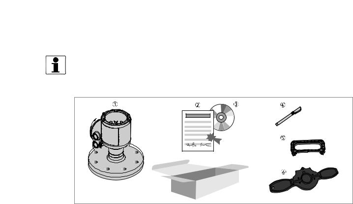
2.1 Scope of delivery
INFORMATION!
Do a check of the packing list to make sure that you have all the elements given in the order.
Figure 2-1: Scope of delivery
1Signal converter, process connection and antenna in the ordered version
2Certificates: calibration etc. (if the device has the appropriate options)
3DVD-ROM (including handbook, technical data sheet and related software)
4Bar magnet
5Display extractor (for removal of the optional display module)
6Cover wrench (for removal of the device covers)
04/2017 - 4004375401 - MA OPTIWAVE 7500 R01 en |
www.krohne.com |
17 |

2 DEVICE DESCRIPTION |
OPTIWAVE 7500 C |
|
2.2 Device description
This device is an 80 GHz FMCW-radar level transmitter. It is a non-contact technology and is 2- wire loop-powered. It is designed to measure the distance, level, mass, volume and reflectivity of liquids, pastes and slurries. For more data about the measuring principle, refer to Measuring principle on page 111.
Radar level transmitters use an antenna to emit a signal to the surface of the measured product. The device has many antennas available. Thus, it can measure most products even in difficult conditions. Also refer to Technical data on page 111.
If the device is ordered with the applicable options, it can be certified for use in hazardous areas.
The signal converter is attached directly to the process connection and the antenna. The illustration that follows shows the types of antenna.
Figure 2-2: Types of antenna
1DN20 (¾¨) Lens antenna made of PEEK.
2DN25 (1¨) Lens antenna made of PEEK.
3DN40 (1½¨) Lens antenna made of PEEK. An antenna extension (length 112 mm / 4.4¨) is available for high nozzles.
4DN70 (2¾¨) Lens antenna made of PEEK.
INFORMATION!
For more data about accessories, refer to Accessories on page 151.
18 |
www.krohne.com |
04/2017 - 4004375401 - MA OPTIWAVE 7500 R01 en |
|
|
DEVICE DESCRIPTION 2 |
|
OPTIWAVE 7500 C |
|
|
|
|
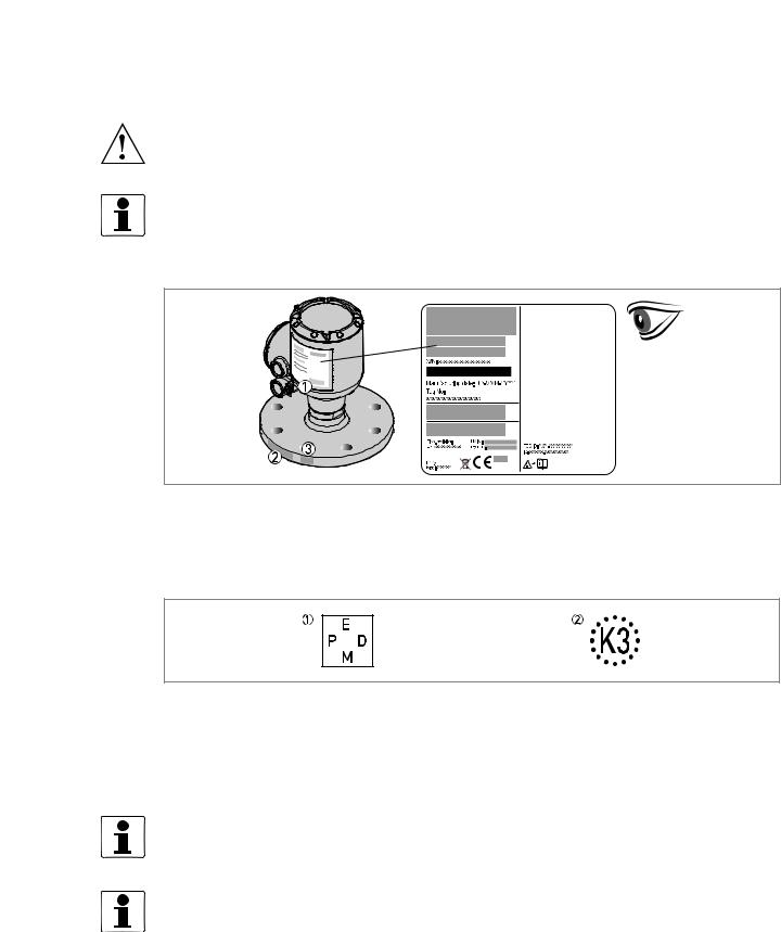
2.3 Visual Check
WARNING!
If the display screen glass is broken, do not touch.
INFORMATION!
Inspect the packaging carefully for damages or signs of rough handling. Report damage to the carrier and to the local office of the manufacturer.
Figure 2-3: Visual check
1Device nameplate (for more data refer to Nameplate (examples) on page 20)
2Process connection data (size and pressure rating, material reference and heat number)
3Gasket material data – refer to the illustration that follows
Figure 2-4: Symbols for the supplied gasket material (on the side of the process connection)
1EPDM
2Kalrez® 6375
If the device is supplied with an FKM/FPM gasket, there is no symbol on the side of the process connection.
INFORMATION!
Look at the device nameplate to ensure that the device is delivered according to your order. Check for the correct supply voltage printed on the nameplate.
INFORMATION!
Compare the material references on the side of the process connection with the order.
04/2017 - 4004375401 - MA OPTIWAVE 7500 R01 en |
www.krohne.com |
19 |
2 DEVICE DESCRIPTION |
OPTIWAVE 7500 C |
|
2.4 Nameplates
INFORMATION!
Look at the device nameplate to ensure that the device is delivered according to your order. Check for the correct supply voltage printed on the nameplate.
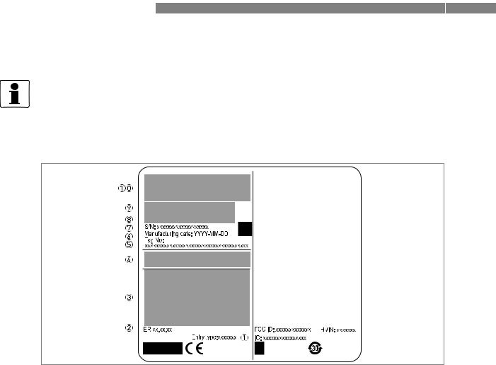
2.4.1 Nameplate (examples)
Figure 2-5: Non-Ex nameplate attached to the housing
1Cable entry size
2Electronic revision (according to NAMUR NE 53)
3Signal output (analog, HART®, fieldbus, etc.), input voltage and maximum current (fieldbus options: basic current)
4Degree of ingress protection (according to EN 60529 / IEC 60529)
5Customer tag number
6Date of manufacture
7Serial number
8Type code (defined in order). For more data, refer to Order code on page 144.
9Model name and number. C = compact version.
10Company logo, name and postal address
Country of manufacture / Company web address
20 |
www.krohne.com |
04/2017 - 4004375401 - MA OPTIWAVE 7500 R01 en |
|
|
INSTALLATION 3 |
|
OPTIWAVE 7500 C |
|
|
|
|
3.1 General notes on installation
INFORMATION!
Inspect the packaging carefully for damages or signs of rough handling. Report damage to the carrier and to the local office of the manufacturer.
INFORMATION!
Do a check of the packing list to make sure that you have all the elements given in the order.
INFORMATION!
Look at the device nameplate to ensure that the device is delivered according to your order. Check for the correct supply voltage printed on the nameplate.
3.2 Storage
WARNING!
Do not keep the device in a vertical position. This will damage the antenna and the device will not measure correctly.
Figure 3-1: Storage conditions
1When you put the device into storage, do not keep it in a vertical position.
2Put the device on its side. We recommend that you use the packaging in which it was delivered.
3Storage temperature range: -40...+85°C / -40...+185°F
•Store the device in a dry and dust-free location.
•Keep the converter out of the sunlight.
•Store the device in its original packing.
04/2017 - 4004375401 - MA OPTIWAVE 7500 R01 en |
www.krohne.com |
21 |
3 INSTALLATION |
OPTIWAVE 7500 C |
|
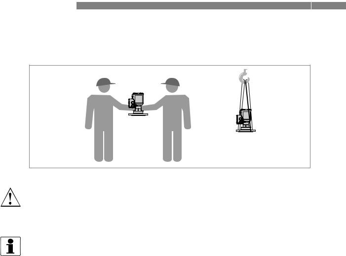
3.3 Transport
Figure 3-2: How to lift the device
WARNING!
Lift the device carefully to prevent damage to the antenna.
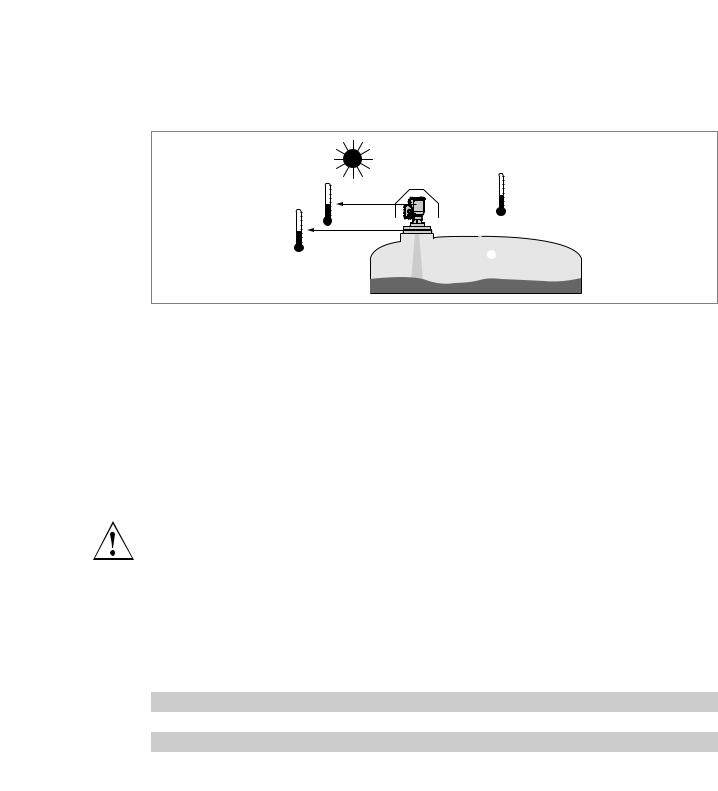
3.4 Pre-installation requirements
INFORMATION!
Obey the precautions that follow to make sure that the device is correctly installed.
•Make sure that there is sufficient space on all sides.
•Protect the signal converter from direct sunlight. If necessary, install the weather protection accessory.
•Do not subject the signal converter to heavy vibrations. The devices are tested for vibration and agree with EN 50178 and IEC 60068-2-6.
22 |
www.krohne.com |
04/2017 - 4004375401 - MA OPTIWAVE 7500 R01 en |
|
|
INSTALLATION 3 |
|
OPTIWAVE 7500 C |
|
|
|
|
3.5 Pressure and temperature ranges
2 |
3 |
|
|
1 |
|
|
4 |
Figure 3-3: Pressure and temperature ranges
1Temperature at the process connection
Non-Ex devices: The temperature range depends on the type of antenna, process connection and the seal material. Refer to the table that follows.
Devices with Hazardous Location approvals: see supplementary instructions
2Ambient temperature for operation of the display -20...+70°C / -4...+158°F
If the ambient temperature is not between these limits, then it is possible that the display screen will not operate temporarily. The device continues to measure level and send an output signal.
3Ambient temperature
Non-Ex devices: -40...+80°C / -40...+176°F
Devices with Hazardous Location approvals: see supplementary instructions
4Process pressure
Depends on the type of antenna and process connection. Refer to the table that follows.
WARNING!
The process connection temperature range must agree with the temperature limits of the gasket material. The operating pressure range is subject to the process connection used and the flange temperature.
Maximum process connection temperature and operating pressure
Antenna type |
Maximum process connection |
Maximum operating pressure |
||
|
temperature |
|
|
|
|
|
|
|
|
|
[°C] |
[°F] |
[barg] |
[psig] |
|
|
|
|
|
Lens DN20, PEEK |
+150 1 |
+302 1 |
40 |
580 |
|
|
|
|
|
Lens DN25, PEEK |
+150 1 |
+302 1 |
40 |
580 |
|
|
|
|
|
Lens DN40, PEEK |
+150 1 |
+302 1 |
40 |
580 |
|
|
|
|
|
Lens DN70, PEEK |
+150 1 |
+302 1 |
40 |
580 |
|
|
|
|
|
1 Pending: +200°C / +392°F
For more data on pressure ratings, refer to Guidelines for maximum operating pressure on page 123.
04/2017 - 4004375401 - MA OPTIWAVE 7500 R01 en |
www.krohne.com |
23 |
3 INSTALLATION |
OPTIWAVE 7500 C |
|
3.6 Recommended mounting position
CAUTION!
Follow these recommendations to make sure that the device measures correctly. They have an effect on the performance of the device.
We recommend that you prepare the installation when the tank is empty.
3.6.1 General notes
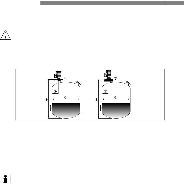
Recommended nozzle position for liquids, pastes and slurries
Figure 3-4: Recommended nozzle position for liquids, pastes and slurries
1Nozzle or socket for the DN20 or DN25 Lens antenna
2Nozzle or socket for the DN40 or DN70 Lens antenna
3Tank diameter
4Minimum distance of the nozzle or socket from the tank wall (depends on the antenna type and size – refer to item 1 in this list):
–DN20 or DN25 Lens : 1/5 × tank height
–DN40 Lens: 1/10 × tank height
–DN70 Lens: 1/20 × tank height
Maximum distance of the nozzle or socket from the tank wall (depends on the antenna type and size – refer to item 1 in this list):
– Lens: 1/3 × tank diameter 5 Tank height
INFORMATION!
If there is a nozzle on the tank before installation, the nozzle must be a minimum of 200 mm / 7.9¨ from the tank wall. The tank wall must be flat and there must not be obstacles adjacent to the nozzle or on the tank wall.
24 |
www.krohne.com |
04/2017 - 4004375401 - MA OPTIWAVE 7500 R01 en |
|
|
INSTALLATION 3 |
|
OPTIWAVE 7500 C |
|
|
|
|
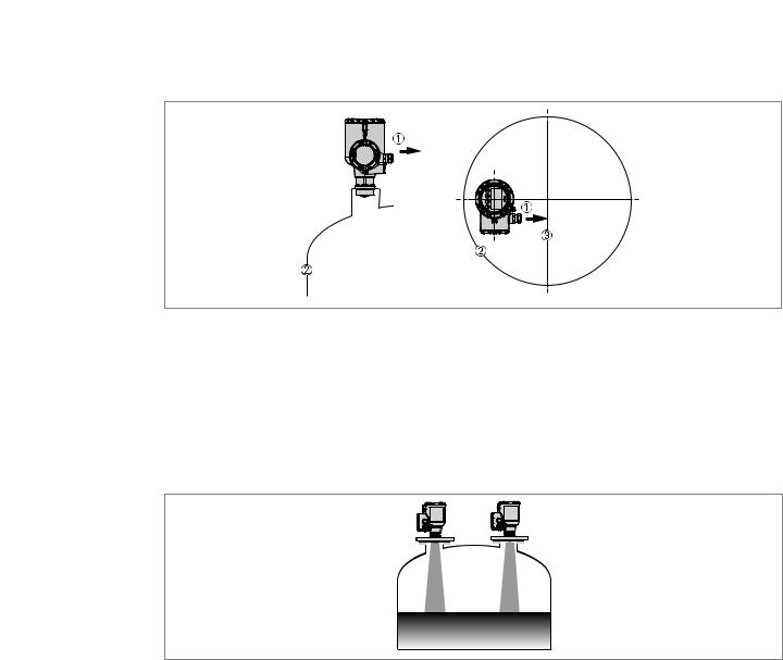
Point the device in the correct direction to get the best performance
Figure 3-5: Point the device in the correct direction to get the best performance
1Cable entry
2Nearest tank wall
3Tank centerline
Point the cable entries on the housing in the direction of the tank centerline.
Number of devices that can be operated in a tank
Figure 3-6: There is no maximum limit to the number of devices that can be operated in the same tank
There is no maximum limit to the number of devices that can be operated in the same tank. They can be installed adjacent to other radar level transmitters.
04/2017 - 4004375401 - MA OPTIWAVE 7500 R01 en |
www.krohne.com |
25 |
3 INSTALLATION |
OPTIWAVE 7500 C |
|
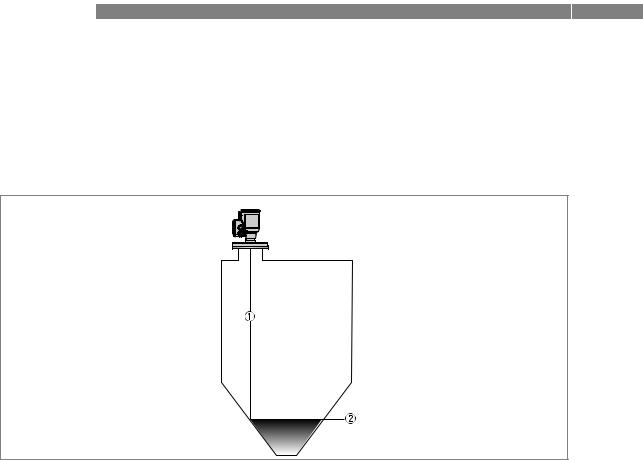
3.6.2 Tanks with dish-shaped and conical bottoms
Dish-shaped or conical bottoms have an effect on the measuring range. The device cannot measure to the bottom of the tank. If possible, install the device as shown in the illustration that follows:
Figure 3-7: Tanks with dish-shaped or conical bottoms
1Axis of radar beam
2Minimum level reading
26 |
www.krohne.com |
04/2017 - 4004375401 - MA OPTIWAVE 7500 R01 en |

|
|
INSTALLATION 3 |
|
OPTIWAVE 7500 C |
|
|
|
|
3.7 Mounting restrictions
CAUTION!
Follow these recommendations to make sure that the device measures correctly. They have an effect on the performance of the device.
We recommend that you prepare the installation when the tank is empty.
3.7.1 General notes
LPR and TLPR devices
WARNING!
LPR (Level Probing Radar) devices measure level in the open air or in a closed space (a metallic tank etc.). TLPR (Tank Level Probing Radar) devices measure level in a closed space only. You can use LPR devices for TLPR applications. For more data, refer to Radio approvals on page 8.
Causes of interference signals
•Objects in the tank or pit.
•Sharp corners that are perpendicular to the path of the radar beam.
•Sudden changes in tank diameter in the path of the radar beam.
CAUTION!
Do not install the device above objects in the tank (agitator etc.) or pit. Objects in the tank or pit can cause interference signals. If there are interference signals, the device will not measure correctly.
If it is not possible to install the device on another part of the tank or pit, do an empty spectrum scan. For more data, refer to Empty spectrum recording on page 89.
Equipment and obstacles: how to prevent measurement of interference signals
Do not put the device immediately above equipment and obstacles in a tank or pit. This can have an effect on the performance of the device.
INFORMATION!
If possible, do not install a nozzle on the tank centerline.
04/2017 - 4004375401 - MA OPTIWAVE 7500 R01 en |
www.krohne.com |
27 |
3 INSTALLATION |
|
|
|
|
|
|
|
|
|
OPTIWAVE 7500 C |
|
||||
|
|
|
|
|
|
|
|
|
|
|
|
|
|
|
|
|
|
|
|
|
|
|
|
|
|
|
|
|
|
|
|
|
|
|
|
|
|
|
|
|
|
|
|
|
|
|
|
|
|
|
|
|
|
|
|
|
|
|
|
|
|
|
|
|
|
|
|
|
|
|
|
|
|
|
|
|
|
|
|
|
|
|
|
|
|
|
|
|
|
|
|
|
|
|
|
|
|
|
|
|
|
|
|
|
|
|
|
|
|
|
|
|
|
|
|
|
|
|
|
|
|
|
|
|
|
|
|
|
|
|
|
|
|
|
|
|
|
|
|
|
|
|
|
|
|
|
|
|
|
|
|
|
|
|
|
|
|
|
|
|
|
|
|
|
|
|
|
|
|
|
|
|
|
|
|
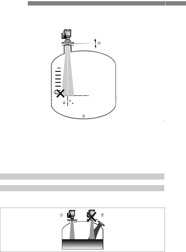
Figure 3-8: Equipment and obstacles: how to prevent measurement of interference signals
1Do not tilt the device more than 2°
2We recommend that you do an empty spectrum recording if there are too many obstacles in the radar beam (for more data, refer to Empty spectrum recording on page 89).
3Beam radius of the antenna: refer to the table below. The beam radius increases by increments of "x" mm for each metre of distance from the antenna.
Beam radius of the antenna
Antenna type |
Beam angle |
Beam radius, x |
|
|
|
|
|
|
|
|
|
[mm/m] |
|
[in/ft] |
|
|
|
|
|
Lens, DN20 (¾¨) |
15° |
132 |
|
1.6 |
|
|
|
|
|
Lens, DN25 (1¨) |
10° |
87 |
|
1.0 |
|
|
|
|
|
Lens, DN40 (1½¨) |
8° |
70 |
|
0.8 |
|
|
|
|
|
Lens, DN70 (2¾¨) |
4° |
35 |
|
0.4 |
|
|
|
|
|
Product inlets
Figure 3-9: Product inlets
1The device is in the correct position.
2The device is too near to the product inlet.
28 |
www.krohne.com |
04/2017 - 4004375401 - MA OPTIWAVE 7500 R01 en |
|
|
INSTALLATION 3 |
|
OPTIWAVE 7500 C |
|
|
|
|
CAUTION!
Do not put the device near to the product inlet. If the product that enters the tank touches the antenna, the device will measure incorrectly. If the product fills the tank directly below the antenna, the device will also measure incorrectly.
INFORMATION!
For more data about the measuring range of each type of antenna, refer to Measuring accuracy on page 119.
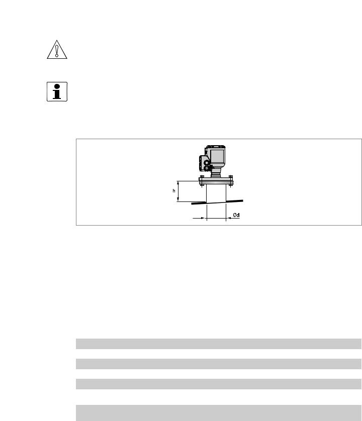
3.7.2 Process connections
Flange connections: installation procedure
Figure 3-10: Flange connections: installation procedure
Ød = nozzle diameter h = nozzle height
Recommended nozzle size for flange connections
The nozzle must be as short as possible. Refer to the table below for the maximum height of the nozzle:
Nozzle and antenna diameter, |
|
|
Maximum nozzle height, h |
|
|
|||||
|
Ød |
|
|
|
|
|
|
|
|
|
|
Lens, DN20 |
Lens, DN25 |
Lens, DN40 |
Lens, DN70 |
||||||
|
|
|
||||||||
|
|
|
|
|
|
|
|
|
|
|
[mm] |
|
[inch] |
[mm] |
[inch] |
[mm] |
[inch] |
[mm] |
[inch] |
[mm] |
[inch] |
|
|
|
|
|
|
|
|
|
|
|
20 |
|
¾ |
50 |
1.97 |
— |
— |
— |
— |
— |
— |
|
|
|
|
|
|
|
|
|
|
|
25 |
|
1 |
50 |
1.97 |
50 |
1.97 |
— |
— |
— |
— |
|
|
|
|
|
|
|
|
|
|
|
40 |
|
1½ |
50 |
1.97 |
50 |
1.97 |
50 1 |
1.97 1 |
— |
— |
|
|
|
|
|
|
|
|
|
|
|
50 |
|
2 |
100 |
3.94 |
100 |
3.94 |
150 1 |
5.91 1 |
— |
— |
|
|
|
|
|
|
|
|
|
|
|
80 |
|
3 |
150 |
5.91 |
150 |
5.91 |
200 1 |
7.87 1 |
250 |
9.84 |
|
|
|
|
|
|
|
|
|
|
|
100 |
|
4 |
150 |
5.91 |
200 |
7.87 |
300 1 |
11.81 |
350 |
13.78 |
|
|
|
|
|
|
|
|
1 |
|
|
|
|
|
|
|
|
|
|
|
|
|
150 |
|
6 |
200 |
7.87 |
300 |
11.81 |
500 1 |
19.69 |
550 |
21.65 |
|
|
|
|
|
|
|
|
1 |
|
|
|
|
|
|
|
|
|
|
|
|
|
200 |
|
8 |
300 |
11.81 |
400 |
15.75 |
700 1 |
27.56 |
750 |
29.53 |
|
|
|
|
|
|
|
|
1 |
|
|
|
|
|
|
|
|
|
|
|
|
|
1 If the device has an antenna extension, this option extends the maximum nozzle height. Add 112 mm / 4.4¨ to this value.
04/2017 - 4004375401 - MA OPTIWAVE 7500 R01 en |
www.krohne.com |
29 |
3 INSTALLATION |
OPTIWAVE 7500 C |
|
Equipment needed:
•Device
•Flange gasket (not supplied)
•Wrench (not supplied)
•Make sure the flange on the nozzle is level.
•Make sure that you use the applicable gasket for the flange dimensions and the process.
•Align the gasket correctly with the flange facing of the nozzle.
•Put the device carefully on the tank flange. Do not attach the device flange to the tank yet
•Make sure that you point the device in the correct direction. For more data, refer to General notes on page 24 ("Point the device in the correct direction").
•Tighten the flange bolts. Refer to local rules and regulations for the correct torque to apply to the bolts.
i End of the procedure.
INFORMATION!
Antenna extensions for devices with flanges
If the device has an antenna extension, this option extends the maximum nozzle height. The antenna extension has a length of 112 mm / 4.4¨.
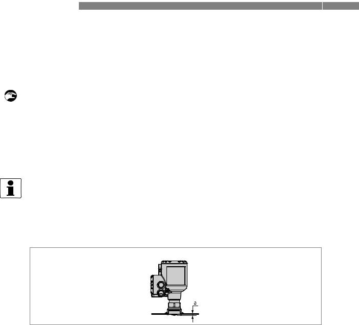
Threaded connections: installation procedure
Figure 3-11: Threaded connections: installation procedure
a = 6 mm / 0.24¨, if the device has an threaded connection and DN20, DN25 or DN40 Lens antenna
Recommended socket size for threaded connections
The socket must be as short as possible. If the socket is in a recess, then use the maximum limits for nozzle dimensions (flange connections) in this section.
If the device has antenna extensions, this option extends the maximum socket height. Add the length of the antenna extensions attached to the device to this value.
Equipment needed:
•Device
•Gasket for G 1½ connection (not supplied)
•Thread seal tape (PTFE) for 1½ NPT connection (not supplied)
•DN20 (¾¨) and DN25 (1¨) Lens antennas: 36 mm open-end wrench (not supplied)
•DN40 (1½¨) and DN70 (2¾¨) Lens antennas: 50 mm open-end wrench (not supplied)
30 |
www.krohne.com |
04/2017 - 4004375401 - MA OPTIWAVE 7500 R01 en |
 Loading...