


 IFC 300 Quick Start
Signal converter for electromagnetic flowmeters
Electronic Revision: ER 3.3.xx
(SW.REV. 3.3x)
The documentation is only complete when used in combination with the relevant documentation for the sensor.
© KROHNE 08/2010 - 4000070303 - QS IFC 300 R06 en

|
CONTENTS |
IFC 300 |
|
|
|
||
|
|
|
|
1 |
Safety instructions |
4 |
|
|
|
|
|
2 |
Installation |
5 |
|
|
|
|
|
|
2.1 |
Intended use ..................................................................................................................... |
5 |
|
2.2 |
Scope of delivery............................................................................................................... |
5 |
|
2.3 |
Storage ............................................................................................................................. |
6 |
|
2.4 |
Transport .......................................................................................................................... |
6 |
|
2.5 |
Installation specifications ................................................................................................ |
6 |
|
2.6 |
Mounting of the compact version..................................................................................... |
7 |
|
2.7 |
Mounting the field housing, remote version .................................................................... |
7 |
|
2.7.1 Pipe mounting ......................................................................................................................... |
7 |
|
|
2.7.2 Wall mounting ......................................................................................................................... |
8 |
|
|
2.7.3 Mounting plate, field housing ................................................................................................. |
9 |
|
|
2.7.4 Turning the display of the field housing version .................................................................. |
10 |
|
|
2.8 |
Mounting the wall-mounted housing, remote version .................................................. |
11 |
|
2.8.1 Pipe mounting ....................................................................................................................... |
11 |
|
|
2.8.2 Wall mounting ....................................................................................................................... |
12 |
|
|
2.8.3 Mounting plate, wall-mounted housing ............................................................................... |
13 |
|
3 Electrical connections |
14 |
||
|
|
|
|
|
3.1 |
Safety instructions.......................................................................................................... |
14 |
|
3.2 |
Important notes on electrical connection...................................................................... |
14 |
|
3.3 |
Electrical cables for remote device versions, notes...................................................... |
15 |
|
3.3.1 Notes on signal cables A and B ............................................................................................ |
15 |
|
|
3.3.2 Notes on field current cable C.............................................................................................. |
15 |
|
|
3.3.3 Requirements for signal cables provided by the customer ................................................. |
16 |
|
|
3.4 |
Preparing the signal and field current cables (except TIDALFLUX) ............................. |
17 |
|
3.4.1 Signal cable A (type DS 300), construction........................................................................... |
17 |
|
|
3.4.2 Preparing signal cable A, connection to signal converter ................................................... |
18 |
|
|
3.4.3 Length of signal cable A........................................................................................................ |
20 |
|
|
3.4.4 Signal cable B (type BTS 300), construction......................................................................... |
21 |
|
|
3.4.5 Preparing signal cable B, connection to signal converter................................................... |
21 |
|
|
3.4.6 Length of signal cable B ....................................................................................................... |
24 |
|
|
3.4.7 Preparing field current cable C, connection to signal converter......................................... |
25 |
|
|
3.4.8 Preparing signal cable A, connection to measuring sensor................................................ |
27 |
|
|
3.4.9 Preparing signal cable B, connection to measuring sensor................................................ |
28 |
|
|
3.4.10 Preparing field current cable C, connection to measuring sensor ................................... |
29 |
|
|
3.5 |
Connecting the signal and field current cables (except TIDALFLUX) ........................... |
30 |
|
3.5.1 Connecting the signal and field current cables, field housing ............................................ |
31 |
|
|
3.5.2 Connecting the signal and field current cables, wall-mounted housing............................. |
32 |
|
|
3.5.3 Connecting the signal and field current cables, 19" rack-mounted housing (28 TE).......... |
33 |
|
|
3.5.4 Connecting the signal and field current cables, 19" rack-mounted housing (21 TE).......... |
34 |
|
|
3.5.5 Connection diagram for measuring sensor, field housing .................................................. |
35 |
|
|
3.5.6 Connection diagram for measuring sensor, wall-mounted housing................................... |
36 |
|
|
3.5.7 Connection diagram for measuring sensor, 19" rack-mounted housing (28 TE)................ |
37 |
|
|
3.5.8 Connection diagram for measuring sensor, 19" rack-mounted housing (21 TE)................ |
38 |
|
2 |
www.krohne.com |
08/2010 - 4000070303 - QS IFC 300 R06 en |

|
|
CONTENTS |
|
|
IFC 300 |
|
|
|
|
|
|
3.6 Preparing and connecting the signal and field current cables (only TIDALFLUX) ....... |
39 |
3.6.1 Cable lengths ........................................................................................................................ |
39 |
3.6.2 Signal cable A (type DS 300), construction........................................................................... |
40 |
3.6.3 Preparing signal cable A, connection to signal converter ................................................... |
41 |
3.6.4 Prepare signal cable A, connect to measuring sensor ........................................................ |
42 |
3.6.5 Signal cable B (type BTS 300), construction......................................................................... |
43 |
3.6.6 Preparing signal cable B, connection to signal converter................................................... |
43 |
3.6.7 Preparing signal cable B, connection to measuring sensor................................................ |
45 |
3.6.8 Preparing field current cable C, connection to signal converter......................................... |
46 |
3.6.9 Preparing field current cable C, connection to measuring sensor ..................................... |
47 |
3.6.10 Interface cable .................................................................................................................... |
49 |
3.6.11 Connection of cables........................................................................................................... |
50 |
3.7 Grounding the measuring sensor .................................................................................. |
51 |
3.7.1 Classical method................................................................................................................... |
51 |
3.7.2 Virtual reference (not valid for TIDALFLUX 4000 & OPTIFLUX 7300 C)............................... |
52 |
3.8 Power supply connection ............................................................................................... |
52 |
3.9 Inputs and outputs, overview ......................................................................................... |
55 |
3.9.1 Combinations of the inputs/outputs (I/Os) ........................................................................... |
55 |
3.9.2 Description of the CG number .............................................................................................. |
56 |
3.9.3 Fixed, non-alterable input/output versions.......................................................................... |
57 |
3.9.4 Alterable input/output versions............................................................................................ |
59 |
3.10 Electrical connection of the inputs and outputs .......................................................... |
60 |
3.10.1 Field housing, electrical connection of the inputs and outputs ......................................... |
60 |
3.10.2 Wall-mounted housing, electrical connection of the inputs and outputs.......................... |
61 |
3.10.3 19" rack-mounted housing (28 TE), electrical connection of the inputs and outputs ....... |
62 |
3.10.4 19" rack-mounted housing (21 TE), electrical connection of the inputs and outputs ....... |
63 |
3.10.5 Laying electrical cables correctly....................................................................................... |
63 |
4 Start-up |
64 |
4.1 Switching on the power .................................................................................................. |
64 |
4.2 Starting the signal converter ......................................................................................... |
64 |
5 Notes |
65 |
08/2010 - 4000070303 - QS IFC 300 R06 en |
www.krohne.com |
3 |
1 SAFETY INSTRUCTIONS |
|
|
IFC 300 |
|
|
|
|
|
Warnings and symbols used
DANGER!
This information refers to the immediate danger when working with electricity.
DANGER!
These warnings must be observed without fail. Even partial disregard of this warning can lead to serious health problems and even death. There is also the risk of seriously damaging the device or parts of the operator's plant.
WARNING!
Disregarding this safety warning, even if only in part, poses the risk of serious health problems. There is also the risk of damaging the device or parts of the operator's plant.
CAUTION!
Disregarding these instructions can result in damage to the device or to parts of the operator's plant.
INFORMATION!
These instructions contain important information for the handling of the device.
HANDLING
•This symbol designates all instructions for actions to be carried out by the operator in the specified sequence.
iRESULT
This symbol refers to all important consequences of the previous actions.
Safety instructions for the operator
CAUTION!
Installation, assembly, start-up and maintenance may only be performed by appropriately trained personnel. The regional occupational health and safety directives must always be observed.
LEGAL NOTICE!
The responsibility as to the suitability and intended use of this device rests solely with the user. The supplier assumes no responsibility in the event of improper use by the customer. Improper installation and operation may lead to loss of warranty. In addition, the "Terms and Conditions of Sale" apply. They appear on the back of the invoice and form the basis of the purchase contract.
INFORMATION!
•Further information can be found on the supplied CD-ROM in the manual, on the data sheet, in special manuals, certificates and on the manufacturer's website.
•If you need to return the device to the manufacturer or supplier, please fill out the form contained on the CD-ROM and send it with the device. Unfortunately, the manufacturer cannot repair or inspect the device without the completed form.
4 |
www.krohne.com |
08/2010 - 4000070303 - QS IFC 300 R06 en |

|
|
INSTALLATION 2 |
|
IFC 300 |
|
|
|
|
2.1 Intended use
The electromagnetic flowmeters are designed exclusively to measure the flow and conductivity of electrically conductive, liquid media.
DANGER!
For devices used in hazardous areas, additional safety notes apply; please refer to the Ex documentation.
WARNING!
If the device is not used according to the operating conditions (refer to chapter "Technical data), the intended protection could be affected.
2.2 Scope of delivery
INFORMATION!
Inspect the cartons carefully for damage or signs of rough handling. Report damage to the carrier and to the local office of the manufacturer.
INFORMATION!
Check the packing list to check if you received completely all that you ordered.
INFORMATION!
Look at the device nameplate to ensure that the device is delivered according to your order. Check for the correct supply voltage printed on the nameplate.
Figure 2-1: Scope of delivery
1Device in the version as ordered
2Documentation (calibration report, Quick Start, CD-Rom with product documentation for measuring sensor and signal converter)
3Signal cable (only for remote version)
08/2010 - 4000070303 - QS IFC 300 R06 en |
www.krohne.com |
5 |

2 INSTALLATION |
|
|
IFC 300 |
|
||
Possible scope of delivery for signal converter / measuring sensor |
|
|
|
|||
|
|
|
|
|
|
|
Measuring sensor |
Measuring sensor + signal converter IFC 300 |
|
|
|
||
|
|
|
|
|
|
|
|
Compact |
Remote field |
Remote wall- |
Remote rack-mounted |
|
|
|
|
housing |
mounted housing |
housing |
|
|
|
|
|
|
R (28 TE) or (21 TE) |
|
|
|
|
|
|
|
|
|
OPTIFLUX 1000 |
OPTIFLUX 1300 C |
OPTIFLUX 1300 F |
OPTIFLUX 1300 W |
OPTIFLUX 1300 R |
|
|
|
|
|
|
|
|
|
OPTIFLUX 2000 |
OPTIFLUX 2300 C |
OPTIFLUX 2300 F |
OPTIFLUX 2300 W |
OPTIFLUX 2300 R |
|
|
|
|
|
|
|
|
|
OPTIFLUX 4000 |
OPTIFLUX 4300 C |
OPTIFLUX 4300 F |
OPTIFLUX 4300 W |
OPTIFLUX 4300 R |
|
|
|
|
|
|
|
|
|
OPTIFLUX 5000 |
OPTIFLUX 5300 C |
OPTIFLUX 5300 F |
OPTIFLUX 5300 W |
OPTIFLUX 5300 R |
|
|
|
|
|
|
|
|
|
OPTIFLUX 6000 |
OPTIFLUX 6300 C |
OPTIFLUX 6300 F |
OPTIFLUX 6300 W |
OPTIFLUX 6300 R |
|
|
|
|
|
|
|
|
|
OPTIFLUX 7000 |
OPTIFLUX 7300 C |
- |
- |
- |
|
|
|
|
|
|
|
|
|
WATERFLUX 3000 |
WATERFLUX 3300 C |
WATERFLUX 3300 F |
WATERFLUX 3300 W |
WATERFLUX 3300 R |
|
|
|
|
|
|
|
|
|
TIDALFLUX 4000 |
- |
TIDALFLUX 4300 F |
- |
- |
|
|
|
|
|
|
|
|
|
2.3Storage
•Store the device in a dry, dust-free location.
•Avoid continuous direct sunlight.
•Store the device in its original packing.
•Storage temperature: -50...+70°C / -58...+158°F
2.4Transport
Signal converter
• No special requirements.
Compact version
•Do not lift the device by the signal converter housing.
•Do not use lifting chains.
•To transport flange devices, use lifting straps. Wrap these around both process connections.
2.5Installation specifications
INFORMATION!
The following precautions must be taken to ensure reliable installation.
•Make sure that there is adequate space to the sides.
•Protect the signal converter from direct sunlight and install a sun shade if necessary.
•Signal converters installed in control cabinets require adequate cooling, e.g. by fan or heat exchanger.
•Do not expose the signal converter to intense vibration. The flowmeters are tested for a vibration level in accordance with IEC 68-2-3.
6 |
www.krohne.com |
08/2010 - 4000070303 - QS IFC 300 R06 en |
|
|
INSTALLATION 2 |
|
IFC 300 |
|
|
|
|
2.6 Mounting of the compact version
INFORMATION!
The signal converter is mounted directly on the measuring sensor. For installation of the flowmeter, please observe the instructions in the supplied product documentation for the measuring sensor.
2.7 Mounting the field housing, remote version
INFORMATION!
Assembly materials and tools are not part of the delivery. Use the assembly materials and tools in compliance with the applicable occupational health and safety directives.
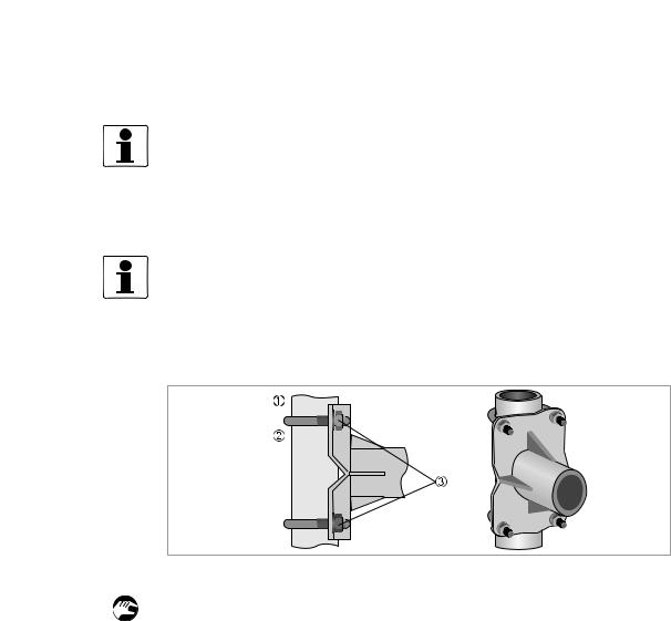
2.7.1 Pipe mounting
Figure 2-2: Pipe mounting of the field housing
1 Fix the signal converter to the pipe.
2Fasten the signal converter using standard U-bolts and washers.
3Tighten the nuts.
08/2010 - 4000070303 - QS IFC 300 R06 en |
www.krohne.com |
7 |
2 INSTALLATION |
IFC 300 |
|
||||||||||||||||||
2.7.2 Wall mounting |
|
|
||||||||||||||||||
|
|
|
|
|
|
|
|
|
|
|
|
|
|
|
|
|
|
|
|
|
|
|
|
|
|
|
|
|
|
|
|
|
|
|
|
|
|
|
|
|
|
|
|
|
|
|
|
|
|
|
|
|
|
|
|
|
|
|
|
|
|
|
|
|
|
|
|
|
|
|
|
|
|
|
|
|
|
|
|
|
|
|
|
|
|
|
|
|
|
|
|
|
|
|
|
|
|
|
|
|
|
|
|
|
|
|
|
|
|
|
|
|
|
|
|
|
|
|
|
|
|
|
|
|
|
|
|
|
|
|
|
|
|
|
|
|
|
|
|
|
|
|
|
|
|
|
|
|
|
|
|
|
|
|
|
|
|
|
|
|
|
|
|
|
|
|
|
|
|
|
|
|
|
|
|
|
|
|
|
|
|
|
|
|
|
|
|
|
|
|
|
|
|
|
|
|
|
|
|
|
|
|
|
|
|
|
|
|
|
|
|
|
|
|
|
|
|
|
|
|
|
|
|
|
|
|
|
|
|
|
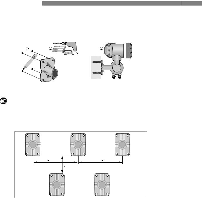
Figure 2-3: Wall mounting of the field housing
1 Prepare the holes with the aid of the mounting plate. For further information refer to Mounting plate, field housing on page 9.
2Use the mounting material and tools in compliance with the applicable occupational health and safety directives.
3Fasten the housing securely to the wall.
Mounting multiple devices next to each other
a ≥ 600 mm / 23.6" |
b ≥ 250 mm / 9.8" |
8 |
www.krohne.com |
08/2010 - 4000070303 - QS IFC 300 R06 en |
|
|
INSTALLATION 2 |
|
IFC 300 |
|
|
|
|
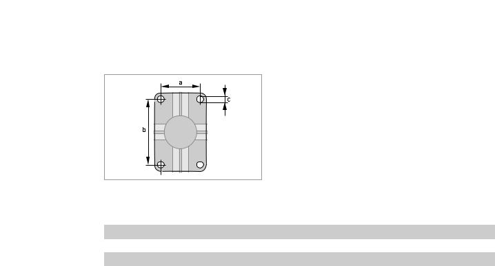
2.7.3 Mounting plate, field housing
Dimensions in mm and inch
|
[mm] |
|
[inch] |
|
|
|
|
a |
|
60 |
2.4 |
|
|
|
|
b |
|
100 |
3.9 |
|
|
|
|
c |
|
Ø9 |
Ø0.4 |
|
|
|
|
08/2010 - 4000070303 - QS IFC 300 R06 en |
www.krohne.com |
9 |
2 INSTALLATION |
IFC 300 |
|
||||||||||||||||||||||||||||||
2.7.4 Turning the display of the field housing version |
|
|
||||||||||||||||||||||||||||||
|
|
|
|
|
|
|
|
|
|
|
|
|
|
|
|
|
|
|
|
|
|
|
|
|
|
|
|
|
|
|
|
|
|
|
|
|
|
|
|
|
|
|
|
|
|
|
|
|
|
|
|
|
|
|
|
|
|
|
|
|
|
|
|
|
|
|
|
|
|
|
|
|
|
|
|
|
|
|
|
|
|
|
|
|
|
|
|
|
|
|
|
|
|
|
|
|
|
|
|
|
|
|
|
|
|
|
|
|
|
|
|
|
|
|
|
|
|
|
|
|
|
|
|
|
|
|
|
|
|
|
|
|
|
|
|
|
|
|
|
|
|
|
|
|
|
|
|
|
|
|
|
|
|
|
|
|
|
|
|
|
|
|
|
|
|
|
|
|
|
|
|
|
|
|
|
|
|
|
|
|
|
|
|
|
|
|
|
|
|
|
|
|
|
|
|
|
|
|
|
|
|
|
|
|
|
|
|
|
|
|
|
|
|
|
|
|
|
|
|
|
|
|
|
|
|
|
|
|
|
|
|
|
|
|
|
|
|
|
|
|
|
|
|
|
|
|
|
|
|
|
|
|
|
|
|
|
|
|
|
|
|
|
|
|
|
|
|
|
|
|
|
|
|
|
|
|
|
|
|
|
|
|
|
|
|
|
|
|
|
|
|
|
|
|
|
|
|
|
|
|
|
|
|
|
|
|
|
|
|
|
|
|
|
|
|
|
|
|
|
|
|
|
|
|
|
|
|
|
|
|
|
|
|
|
|
|
|
|
|
|
|
|
|
|
|
|
|
|
|
|
|
|
|
|
|
|
|
|
|
|
|
|
|
|
|
|
|
|
|
|
|
|
|
|
|
|
|
|
|
|
|
|
|
|
|
|
|
|
|
|
|
|
|
|
|
|
|
|
|
|
|
|
|
|
|
|
|
|
|
|
|
|
|
|
|
|
|
|
|
|
|
|
|
|
|
|
|
|
|
|
|
|
|
|
|
|
|
|
|
|
|
|
|
|
|
|
|
|
|
|
|
|
|
|
|
|
|
|
|
|
|
|
|
|
|
|
|
|
|
|
|
|
|
|
|
|
|
|
|
|
|
|
|
|
|
|
|
|
|
|
|
|
|
|
|
|
|
|
|
|
|
|
|
|
|
|
|
|
|
|
|
|
|
|
|
|
|
|
|
|
|
|
|
|
|
|
|
|
|
|
|
|
|
|
|
|
|
|
|
|
|
|
|
|
|
|
|
|
|
|
|
|
|
|
|
|
|
|
|
|
|
|
|
|
|
|
|
|
|
|
|
|
|
|
|
|
|
|
|
|
|
|
|
|
|
|
|
|
|
|
|
|
|
|
|
|
|
|
|
|
|
|
|
|
|
|
|
|
|
|
|
|
|
|
|
|
|
|
|
|
|
|
|
|
|
|
|
|
|
|
|
|
|
|
|
|
|
|
|
|
|
|
|
|
|
|
|
|
|
|
|
|
|
|
|
|
|
|
|
|
|
|
|
|
|
|
|
|
|
|
|
|
|
|
|
|
|
|
|
|
|
|
|
|
|
|
|
|
|
|
|
|
|
|
|
|
|
|
|
|
|
|
|
|
|
|
|
|
|
|
|
|
|
|
|
|
|
|
|
|
|
|
|
|
|
|
|
|
|
|
|
|
|
|
|
|
|
|
|
|
|
|
|
|
|
|
|
|
|
|
|
|
|
|
|
|
|
|
|
|
|
|
|
|
|
|
|
|
|
|
|
|
|
|
|
|
|
|
|
|
|
|
|
|
|
|
|
|
|
|
|
|
|
|
|
|
|
|
|
|
|
|
|
|
|
|
|
|
|
|
|
|
|
|
|
|
|
|
|
|
|
|
|
|
|
|
|
|
|
|
|
|
|
|
|
|
|
|
|
|
|
|
|
|
|
|
|
|
|
|
|
|
|
|
|
|
|
|
|
|
|
|
|
|
|
|
|
|
|
|
|
|
|
|
|
|
|
|
|
|
|
|
|
|
|
|
|
|
|
|
|
|
|
|
|
|
|
|
|
|
|
|
|
|
|
|
|
|
|
|
|
|
|
|
|
|
|
|
|
|
|
|
|
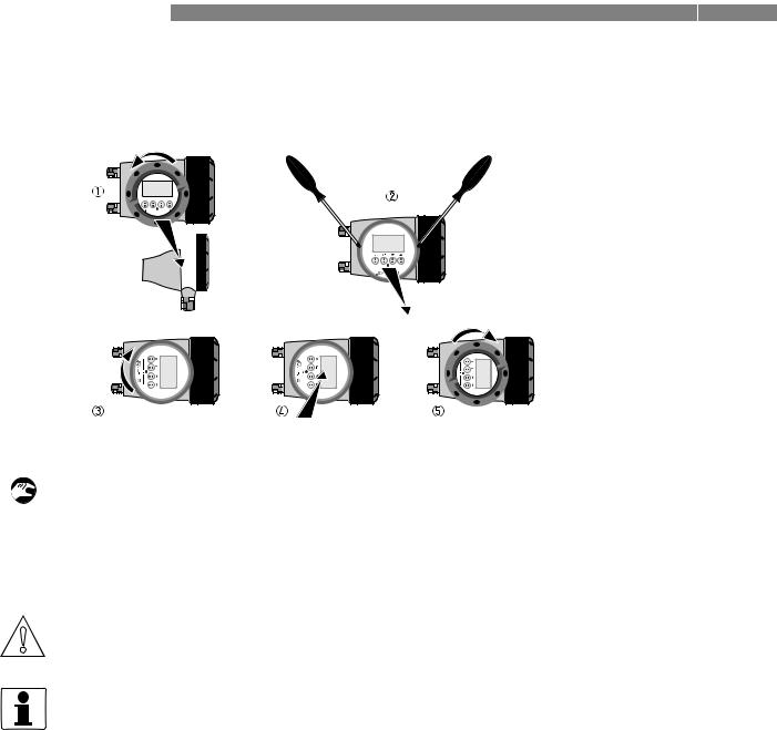
Figure 2-4: Turning the display of the field housing version
The display of the field housing version can be turned in 90° increments.
1Unscrew the cover from the display and operation control unit.
2Using a suitable tool, pull out the two metal puller devices to the left and right of the display.
3Pull out the display between the two metal puller devices and rotate it to the required position.
4Slide the display and then the metal puller devices back into the housing.
5Re-fit the cover and tighten it by hand.
CAUTION!
The ribbon cable of the display must not be folded or twisted repeatedly.
INFORMATION!
Each time a housing cover is opened, the thread should be cleaned and greased. Use only resinfree and acid-free grease.
Ensure that the housing gasket is properly fitted, clean and undamaged.
10 |
www.krohne.com |
08/2010 - 4000070303 - QS IFC 300 R06 en |
|
|
INSTALLATION 2 |
|
IFC 300 |
|
|
|
|
2.8 Mounting the wall-mounted housing, remote version
INFORMATION!
Assembly materials and tools are not part of the delivery. Use the assembly materials and tools in compliance with the applicable occupational health and safety directives.
2.8.1 Pipe mounting
Figure 2-5: Pipe mounting of the wall-mounted housing
1 Fasten the mounting plate to the pipe with standard U-bolts, washers and fastening nuts. 2 Screw the signal converter to the mounting plate with the nuts and washers.
08/2010 - 4000070303 - QS IFC 300 R06 en |
www.krohne.com |
11 |
2 INSTALLATION |
|
|
|
IFC 300 |
|
||||||||||||
2.8.2 Wall mounting |
|
|
|
|
|
||||||||||||
|
|
|
|
|
|
|
|
|
|
|
|
|
|
|
|
|
|
|
|
|
|
|
|
|
|
|
|
|
|
|
|
|
|
|
|
|
|
|
|
|
|
|
|
|
|
|
|
|
|
|
|
|
|
|
|
|
|
|
|
|
|
|
|
|
|
|
|
|
|
|
|
|
|
|
|
|
|
|
|
|
|
|
|
|
|
|
|
|
|
|
|
|
|
|
|
|
|
|
|
|
|
|
|
|
|
|
|
|
|
|
|
|
|
|
|
|
|
|
|
|
|
|
|
|
|
|
|
|
|
|
|
|
|
|
|
|
|
|
|
|
|
|
|
|
|
|
|
|
|
|
|
|
|
|
|
|
|
|
|
|
|
|
|
|
|
|
|
|
|
|
|
|
|
|
|
|
|
|
|
|
|
|
|
|
|
|
|
|
|
|
|
|
|
|
|
|
|
|
|
|
|
|
|
|
|
|
|
|
|
|
|
|
|
|
|
|
|
|
|
|
|
|
|
|
|
|
|
|
|
|
|
|
|
|
|
|
|
|
|
|
|
|
|
|
|
|
|
|
|
|
|
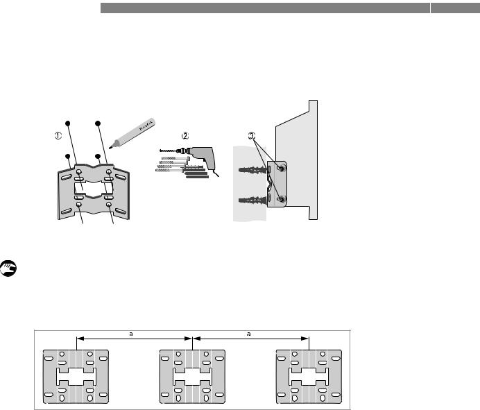
Figure 2-6: Wall mounting of the wall-mounted housing
1 Prepare the holes with the aid of the mounting plate. For further information refer to Mounting plate, wall-mounted housing on page 13.
2Fasten the mounting plate securely to the wall.
3Screw the signal converter to the mounting plate with the nuts and washers.
Mounting multiple devices next to each other
a ≥ 240 mm / 9.4" |
12 |
www.krohne.com |
08/2010 - 4000070303 - QS IFC 300 R06 en |
|
|
INSTALLATION 2 |
|
IFC 300 |
|
|
|
|
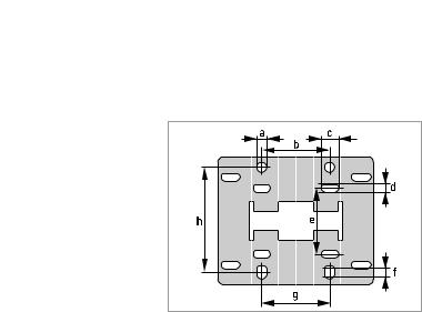
2.8.3 Mounting plate, wall-mounted housing
Dimensions in mm and inch
|
[mm] |
|
[inch] |
|
|
|
|
a |
|
Ø9 |
Ø0.4 |
b |
|
64 |
2.5 |
|
|
|
|
c |
|
16 |
0.6 |
d |
|
6 |
0.2 |
|
|
|
|
e |
|
63 |
2.5 |
f |
|
4 |
0.2 |
|
|
|
|
g |
|
64 |
2.5 |
h |
|
98 |
3.85 |
|
|
|
|
08/2010 - 4000070303 - QS IFC 300 R06 en |
www.krohne.com |
13 |
3 ELECTRICAL CONNECTIONS |
|
|
IFC 300 |
|
|
|
|
|
3.1 Safety instructions
DANGER!
All work on the electrical connections may only be carried out with the power disconnected. Take note of the voltage data on the nameplate!
DANGER!
Observe the national regulations for electrical installations!
DANGER!
For devices used in hazardous areas, additional safety notes apply; please refer to the Ex documentation.
WARNING!
Observe without fail the local occupational health and safety regulations. Any work done on the electrical components of the measuring device may only be carried out by properly trained specialists.
INFORMATION!
Look at the device nameplate to ensure that the device is delivered according to your order. Check for the correct supply voltage printed on the nameplate.
3.2 Important notes on electrical connection
DANGER!
Electrical connection is carried out in conformity with the VDE 0100 directive "Regulations for electrical power installations with line voltages up to 1000 V" or equivalent national regulations.
CAUTION!
•Use suitable cable entries for the various electrical cables.
•The sensor and converter are configured together in the factory. For this reason, please connect the devices in pairs. Ensure that the sensor constant GK/GKL (see type plates) are identically set.
•If delivered separately or when installing devices that were not configured together, set the converter to the DN size and GK/GKL of the sensor.
14 |
www.krohne.com |
08/2010 - 4000070303 - QS IFC 300 R06 en |

|
|
ELECTRICAL CONNECTIONS 3 |
|
IFC 300 |
|
|
|
|
3.3 Electrical cables for remote device versions, notes
3.3.1 Notes on signal cables A and B
INFORMATION!
The signal cables A (type DS 300) with double shield and B (type BTS 300) with triple shield ensure proper transmission of measured values.
Observe the following notes:
•Lay the signal cable with fastening elements.
•It is permissible to lay the signal cable in water or in the ground.
•The insulating material is flame-retardant to EN 50625-2-1, IEC 60322-1.
•The signal cable does not contain any halogens and is unplasticized, and remains flexible at low temperatures.
•The connection of the inner shield is carried out via the stranded drain wire (1).
•The connection of the outer shield is carried out via the shield (60) or the stranded drain wire (6), depending on the housing version. Observe the following notes.
•The signal cable type B cannot be used with options with "virtual reference"!
3.3.2Notes on field current cable C
DANGER!
All versions except TIDALFLUX:
A non-shielded three-wire copper cable is sufficient for the field current cable. If you nevertheless use shielded cables, the shield must NOT be connected in the housing of the signal converter.
Only TIDALFLUX:
A shielded two-wire copper cable is used as the field current cable. The shielding MUST be connected in the housing of the measuring sensor and signal converter.
INFORMATION!
The field current cable is not part of the scope of delivery.
08/2010 - 4000070303 - QS IFC 300 R06 en |
www.krohne.com |
15 |

3 ELECTRICAL CONNECTIONS |
|
|
IFC 300 |
|
|
|
|
|
3.3.3 Requirements for signal cables provided by the customer
INFORMATION!
If the signal cable was not ordered, it is to be provided by the customer. The following requirements regarding the electrical values of the signal cable must be observed:
Electrical safety
• To EN 60811 (Low Voltage Directive) or equivalent national regulations.
Capacitance of the insulated conductors
•Insulated conductor / insulated conductor < 50 pF/m
•Insulated conductor / shield < 150 pF/m
Insulation resistance
•Riso > 100 GΩ x km
•Umax < 24 V
•Imax < 100 mA
Test voltages
•Insulated conductor / inner shield 500 V
•Insulated conductor / insulated conductor 1000 V
•Insulated conductor / outer shield 1000 V
Twisting of the insulated conductors
• At least 10 twists per meter, important for screening magnetic fields.
16 |
www.krohne.com |
08/2010 - 4000070303 - QS IFC 300 R06 en |
|
|
ELECTRICAL CONNECTIONS 3 |
|
IFC 300 |
|
|
|
|
3.4 Preparing the signal and field current cables (except TIDALFLUX)
INFORMATION!
Assembly materials and tools are not part of the delivery. Use the assembly materials and tools in compliance with the applicable occupational health and safety directives.
The electrical connection of the outer shield is different for the various housing variants. Please observe the corresponding instructions.
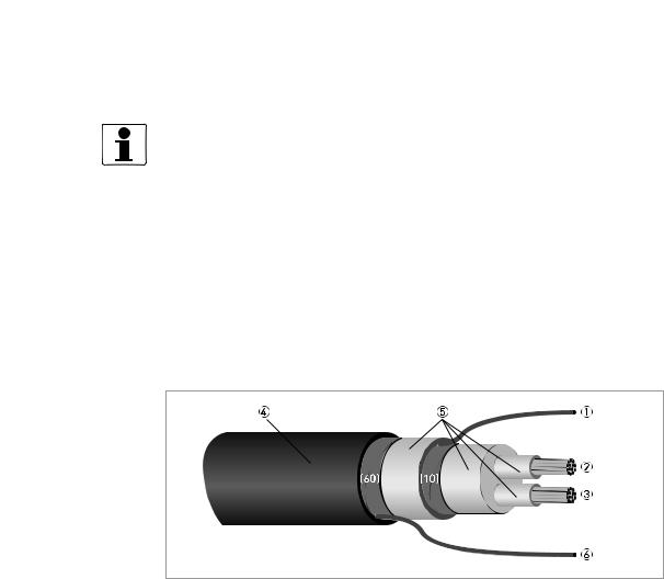
3.4.1Signal cable A (type DS 300), construction
•Signal cable A is a double-shielded cable for signal transmission between the measuring sensor and signal converter.
•Bending radius: ≥ 50 mm / 2"
Figure 3-1: Construction of signal cable A
1Stranded drain wire (1) for the inner shield (10), 1.0 mm2 Cu / AWG 17 (not insulated, bare)
2Insulated wire (2), 0.5 mm2 Cu / AWG 20
3Insulated wire (3), 0.5 mm2 Cu / AWG 20
4Outer sheath
5Insulation layers
6Stranded drain wire (6) for the outer shield (60)
08/2010 - 4000070303 - QS IFC 300 R06 en |
www.krohne.com |
17 |
3 ELECTRICAL CONNECTIONS |
|
|
IFC 300 |
|
|
|
|
|
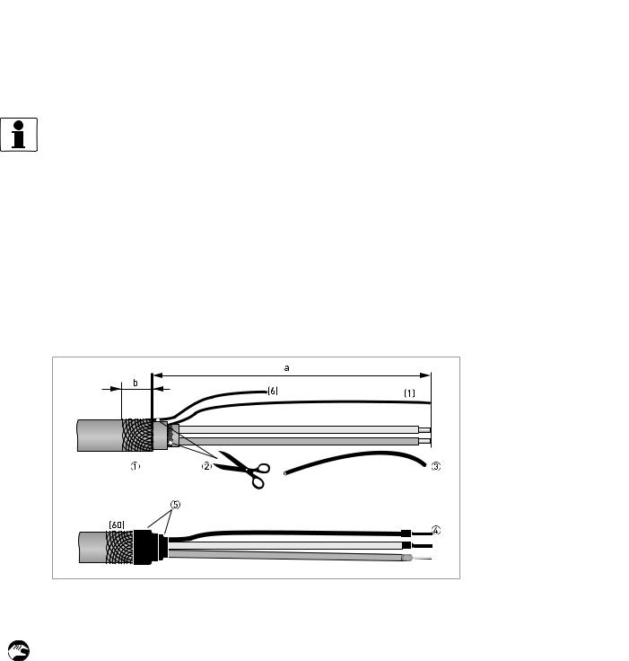
3.4.2 Preparing signal cable A, connection to signal converter
Field housing
INFORMATION!
Assembly materials and tools are not part of the delivery. Use the assembly materials and tools in compliance with the applicable occupational health and safety directives.
•The outside shield (60) is connected in the field housing directly via the shield and a clip.
•Bending radius: ≥ 50 mm / 2"
Required materials:
•PVC insulation tubing, Ø2.5 mm / 0.1"
•Heat-shrinkable tubing
•Wire end ferrule to DIN 46 228: E 1.5-8 for the stranded drain wire (1)
•2x wire end ferrules to DIN 46 228: E 0.5-8 for the insulated conductors (2, 3)
Figure 3-2: Signal cable A, preparation for field housing
a = 80 mm / 3.15" b = 10 mm / 0.39"
1 Strip the conductor to dimension a.
Trim the outer shield to dimension b and pull it over the outer sheath.
2Cut off the inner shield (10) and the stranded drain wire (6). Make sure not to damage the stranded drain wire (1).
3Slide an insulating tube over the stranded drain wire (1).
4Crimp the wire end ferrules onto the conductors (2, 3) and stranded drain wire.
5Pull the heat-shrinkable tubing over the prepared signal cable.
18 |
www.krohne.com |
08/2010 - 4000070303 - QS IFC 300 R06 en |
|
|
ELECTRICAL CONNECTIONS 3 |
|
IFC 300 |
|
|
|
|
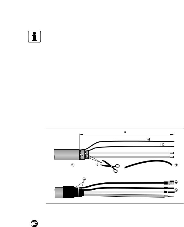
Wall mounted housing
INFORMATION!
Assembly materials and tools are not part of the delivery. Use the assembly materials and tools in compliance with the applicable occupational health and safety directives.
•The connection of the outer shield (60) is carried out in the wall-mounted housing via the stranded drain wire (6).
•Bending radius: ≥ 50 mm / 2"
Required materials
•Push-on connector 6.3 mm / 0.25", insulation to DIN 46245 for conductor Ø = 0.5...1 mm2 / AWG 20...17
•PVC insulation tubing, Ø2.5 mm / 0.1"
•Heat-shrinkable tubing
•Wire end ferrule to DIN 46 228: E 1.5-8 for the stranded drain wire (1)
•2x wire end ferrules to DIN 46 228: E 0.5-8 for the insulated conductors (2, 3)
Figure 3-3: Signal cable A, preparation for wall-mounted housing a = 80 mm / 3.15"
1 Strip the conductor to dimension a.
2Cut off the inner shield (10) and the outer shield (60). Make sure not to damage the stranded drain wires (1) and (6).
3Slide the insulation tubing over the stranded drain wires.
4Crimp the push-on connector onto the stranded drain wire (6).
5Crimp the wire end ferrules onto the conductors (2, 3) and stranded drain wire (1).
6Pull the heat-shrinkable tubing over the prepared signal cable.
08/2010 - 4000070303 - QS IFC 300 R06 en |
www.krohne.com |
19 |

3 ELECTRICAL CONNECTIONS |
|
|
IFC 300 |
|
|
|
|
|
3.4.3 Length of signal cable A
INFORMATION!
For temperatures of the medium above 150°C / 300°F, a special signal cable and a ZD intermediate socket are necessary. These are available including the changed electrical connection diagrams.
Measuring sensor |
Nominal size |
|
|
Min. electrical |
Curve for signal |
||
|
|
|
|
|
|
conductivity |
cable A |
|
DN [mm] |
[inch] |
|||||
|
[µS/cm] |
|
|||||
|
|
|
|
|
|
|
|
OPTIFLUX 1000 F |
10... |
150 |
3/8... |
6 |
5 |
A1 |
|
|
|
|
|
|
|
|
|
OPTIFLUX 2000 F |
25... |
150 |
1... |
6 |
|
20 |
A1 |
|
|
|
|
|
|
|
|
|
200... |
2000 |
8... |
80 |
20 |
A2 |
|
|
|
|
|
|
|
|
|
OPTIFLUX 4000 F |
2.5... |
150 |
1/10... |
6 |
1 |
A1 |
|
|
|
|
|
|
|
|
|
|
200... |
2000 |
8... |
80 |
1 |
A2 |
|
|
|
|
|
|
|
|
|
OPTIFLUX 5000 F |
2.5... |
100 |
1/10... |
4 |
1 |
A1 |
|
|
|
|
|
|
|
|
|
|
150... |
250 |
6... |
10 |
1 |
A2 |
|
|
|
|
|
|
|
|
|
OPTIFLUX 6000 F |
2.5... |
150 |
1/10... |
6 |
1 |
A1 |
|
WATERFLUX 3000 F |
25...600 |
1...24 |
20 |
A1 |
Figure 3-4: Maximum length of signal cable A
1Maximum length of signal cable A between the measuring sensor and signal converter [m]
2Maximum length of signal cable A between the measuring sensor and signal converter [ft]
3Electrical conductivity of the medium being measured [μS/cm]
20 |
www.krohne.com |
08/2010 - 4000070303 - QS IFC 300 R06 en |
|
|
ELECTRICAL CONNECTIONS 3 |
|
IFC 300 |
|
|
|
|
3.4.4Signal cable B (type BTS 300), construction
•Signal cable B is a triple-shielded cable for signal transmission between the measuring sensor and signal converter.
•Bending radius: ≥ 50 mm / 2"
Figure 3-5: Construction of signal cable B
1Stranded drain wire for the inner shield (10), 1.0 mm2 Cu / AWG 17 (not insulated, bare)
2Insulated wire (2), 0.5 mm2 Cu / AWG 20 with stranded drain wire (20) of shield
3Insulated wire (3), 0.5 mm2 Cu / AWG 20 with stranded drain wire (30) of shield
4Outer sheath
5Insulation layers
6Stranded drain wire (6) for the outer shield (60), 0.5 mm2 Cu / AWG 20 (not insulated, bare)
3.4.5Preparing signal cable B, connection to signal converter
Field housing
INFORMATION!
Assembly materials and tools are not part of the delivery. Use the assembly materials and tools in compliance with the applicable occupational health and safety directives.
•The outside shield (60) is connected in the field housing directly via the shield and a clip.
•Bending radius: ≥ 50 mm / 2"
Required materials
•PVC insulation tubing, Ø2.0...2.5 mm / 0.08...0.1"
•Heat-shrinkable tubing
•Wire end ferrule to DIN 46 228: E 1.5-8 for the stranded drain wire (1)
•4 wire end ferrules to DIN 46 228: E 0.5-8 for the insulated conductors 2 and 3 and the stranded drain wires (20, 30)
08/2010 - 4000070303 - QS IFC 300 R06 en |
www.krohne.com |
21 |
 Loading...