


 OPTIFLEX 7200 C/F/S/D Technical Datasheet
Guided radar (TDR) level transmitter for liquids in storage and process applications
•Premium device for level and interface measurement in the chemical, oil and gas industries
•Extensive choice of probes for all applications with ±2 mm / 0.08¨ accuracy
•SIL 2/3-certified current and relay outputs
© KROHNE 07/2019 - 4006447902 - TD OPTIFLEX 7200 R02 en

|
CONTENTS |
OPTIFLEX 7200 C/F/S/D |
|
|
|
||
|
|
|
|
1 Product features |
3 |
|
1.1 |
The modular TDR level transmitter for storage and process applications |
.................... 3 |
1.2 |
Applications ...................................................................................................................... |
4 |
1.3 |
Product family .................................................................................................................. |
5 |
1.4 |
Application table for probe selection ............................................................................... |
8 |
1.5 |
Measuring principle.......................................................................................................... |
8 |
2 Technical data |
11 |
|
2.1 |
Technical data................................................................................................................. |
11 |
2.2 |
Minimum power supply voltage ..................................................................................... |
24 |
2.3 |
Process pressure and process connection temperature limits.................................... |
25 |
2.4 |
Measurement limits ....................................................................................................... |
28 |
2.5 |
Dimensions and weights ................................................................................................ |
36 |
2.5.1 General notes........................................................................................................................ |
36 |
|
2.5.2 Primary components ............................................................................................................ |
36 |
|
2.5.3 Signal converter and probe electronics options .................................................................. |
37 |
|
2.5.4 Process connection options.................................................................................................. |
44 |
|
2.5.5 Probe options ........................................................................................................................ |
46 |
|
2.5.6 Weather protection option .................................................................................................... |
51 |
|
3 Installation |
53 |
|
3.1 |
Intended use ................................................................................................................... |
53 |
3.2 |
How to prepare the tank before you install the device.................................................. |
53 |
3.2.1 General information for nozzles........................................................................................... |
53 |
|
3.3 |
Installation recommendations for liquids...................................................................... |
56 |
3.3.1 General requirements .......................................................................................................... |
56 |
|
3.3.2 Installation in standpipes (stilling wells and bypass chambers) ......................................... |
57 |
|
4 Electrical connections |
59 |
|
4.1 |
Electrical installation: 2-wire, loop-powered ................................................................ |
59 |
4.1.1 Compact version ................................................................................................................... |
59 |
|
4.1.2 Remote version ..................................................................................................................... |
60 |
|
4.2 |
Non-Ex devices............................................................................................................... |
62 |
4.3 |
Devices for hazardous locations .................................................................................... |
64 |
4.4 |
Networks ........................................................................................................................ |
64 |
4.4.1 General information.............................................................................................................. |
64 |
|
4.4.2 Point-to-point networks ....................................................................................................... |
64 |
|
4.4.3 Multi-drop networks ............................................................................................................. |
65 |
|
5 Order information |
66 |
|
5.1 |
Order code ...................................................................................................................... |
66 |
6 Notes |
|
73 |
2 |
www.krohne.com |
07/2019 - 4006447902 - TD OPTIFLEX 7200 R02 en |

|
|
PRODUCT FEATURES 1 |
|
OPTIFLEX 7200 C/F/S/D |
|
|
|
|
1.1 The modular TDR level transmitter for storage and process applications
OPTIFLEX 7200 is the premium device for level and interface measurement in the chemical, oil and gas industries. It has a large range of probe options and a modular design that permits it to be installed in small spaces. It also has a Dynamic Gas-phase Compensation (DGC) mode that allows it to measure accurately in processes where the composition of the gas above the liquid can change rapidly.
1Extensive choice of probes for all applications with ±2 mm / 0.08¨ accuracy. It is also possible to measure interface in "reversed interface" conditions (e.g. water / CS2).
2Aluminium or stainless steel housing
3Optional LCD screen with 4-button keypad
4Quick coupling system: converter is rotatable and removable under process conditions
The display can be ordered with the device or as an accessory. It shows measurement data on a 128 × 64 pixel screen. The configuration menu permits the device to be set up in a small number of intuitive steps.
Highlights
•Process conditions up to +250°C / +482°F and 100 barg / 1450 psig
•2-wire 4…20 mA (HART® 7) with optional second output (current or switch/relay)
•Measuring distance up to 60 m / 196.85 ft; level and interface measurement
•SIL 2/3-compliant: 1 current output, 2 current outputs, or 1 current output + 1 switch output (relay)
•Patented Dynamic Gas-phase Compensation (DGC) permits accurate level measurement in tanks with changing gas properties without increasing the size of the dead zone
•Stainless steel housing for corrosive environment
•Real-time clock for event logging
•3-year warranty
•Can measure interface when the top product has a depth of only 50 mm / 1.97¨
•Optional ceramic process seal system for demanding process conditions
07/2019 - 4006447902 - TD OPTIFLEX 7200 R02 en |
www.krohne.com |
3 |

1 PRODUCT FEATURES |
OPTIFLEX 7200 C/F/S/D |
|
•Various converter and electronic versions to facilitate access to the device:
-Remote converter up to 115 m / 377.30 ft from the probe
-Horizontal or vertical housing to suit every installation
•Diagnosis functions supply data according to NAMUR NE 107
•PACTware™, HART® DD and DTM provided free of charge with full functionality
•Quick setup assistant for easy commissioning
•Display keypad directly accessible without opening the cover
Industries
•Chemical & Petrochemical
•Oil & Gas
•Power
Applications
Liquids in storage and process applications: ≤60 m / 196.85 ft; ≤+250°C / +482°F; ≤100 barg / 1450 psig
•Storage – Chemical – Solvents, alcohols, Acids, bases, Ethylene, Propylene, Additives, CO2, NH3 etc.
•Storage & reactors – Chemical – Foaming agents
•Storage & process & reactors – Oil & Gas – Hydrocarbons
•Storage – Oil & Gas – Liquefied gases
•Remote level control on a chemical production site
•Monitoring level in a plasticizer tank with agitator (stilling well installation)
•Hydrocarbon level measurement in a refinery
1.2Applications
1. Level measurement of liquids
The level transmitter can measure the level of a wide range of liquid products on a large variety of installations within the stated pressure and temperature range. It does not require any calibration: it is only necessary to adapt the probe length and do a short configuration procedure.
|
|
|
|
|
|
|
|
|
|
|
|
|
|
|
|
|
|
|
|
|
|
|
|
4 |
|
|
|
www.krohne.com |
07/2019 - 4006447902 - TD OPTIFLEX 7200 R02 en |

|
|
PRODUCT FEATURES 1 |
|
OPTIFLEX 7200 C/F/S/D |
|
|
|
|
2. Volume measurement
A conversion table (strapping table) function is
available in the configuration menu for volume or mass measurement. Up to 30 volume values can be related to level values. For example:
Level 1= 2 m / Volume 1= e.g. 0.7 m³ Level 2= 10 m / Volume 2= e.g. 5 m³ Level 3= 20 m / Volume 3= e.g. 17 m³
This data permits the device to calculate volumes between strapping table entries.
1.3 Product family
OPTIFLEX 1100 C
for continuous measurement of liquids and solids up to 16 barg (232 psig) and +100°C (+212°F)
OPTIFLEX 1100 C is a 2-wire TDR level transmitter for measuring distance, level, volume and mass of liquids and solids. Its simple, compact design allows technicians to quickly assemble the probe and attach it to a threaded connection. It is an affordable solution for applications that do not require a high level of accuracy and is also an excellent alternative to traditional level controls such as RF Capacitance, conductive and DP transmitters.
It is ideal for level measurement in buffer tanks, collectors and simple process applications and silo level monitoring in quarrying and agriculture.
07/2019 - 4006447902 - TD OPTIFLEX 7200 R02 en |
www.krohne.com |
5 |

1 PRODUCT FEATURES |
OPTIFLEX 7200 C/F/S/D |
|
OPTIFLEX 3200 C/F
for liquids with hygienic requirements up to 40 barg (580 psig) and +150°C (+302°F)
This TDR level transmitter, with its hygienic design, is ideal for measuring measure level and interface in small vessels and tanks with CIP/SIP cycles. It can also be installed in tanks up to 4 m / 13.12 ft high.
Probe options include:
•a single rod probe made of stainless steel with a
surface roughness of Ra <0.76 μm / 30 μin – AARH, and
•a single rod probe and process connection that are entirely coated with PTFE (TFM-T62, FDA-approved)
OPTIFLEX 6200 C/F
for solids from granulates to powders up to 40 barg (580 psig) and +200°C (392°F)
This level transmitter measures granulates and powders in deep pits or high containers. It has a maximum measuring distance of 40 m / 131.2 ft.
Its durable design can withstand traction loads up to 3500 kg (7700 lb) and electrostatic discharges up to 30 kV. A specially developed set of algorithms also permits the device to accurately measure the level of low-reflective media.
6 |
www.krohne.com |
07/2019 - 4006447902 - TD OPTIFLEX 7200 R02 en |

|
|
PRODUCT FEATURES 1 |
|
OPTIFLEX 7200 C/F/S/D |
|
|
|
|
OPTIFLEX 7200 C/F/S/D
for liquids in storage and process applications up to 100 barg (1450 psig) and 250°C (482°F)
The OPTIFLEX 7200 is designed specifically for measuring level and interface in the chemical, oil and gas industries. It can be used in high tanks (max. height 60 m / 197 ft) and pressure vessels.
It has many probe options, making it suitable for a wide range of process conditions. It can also measure volatile products such as carbon disulphide using the reversed interface probe.
The device's software also permits the device to accurately measure the level of products in processes where the composition of the gas above the product can change suddenly. This uses a patented algorithm called "Dynamic Gas-phase Compensation" (DGC).
OPTIFLEX 8200 C/F/S
for liquids at high temperature and pressure up to 320 barg (4641 psig) and 315°C (599°F)
This level transmitter is designed specifically for measuring level and interface in extreme conditions such as boilers in the power, oil and gas industries.
It can be used in very high tanks (max. height 60 m / 197 ft). It can be equipped with a stainless steel housing for corrosive environments.
The device's software also permits the device to accurately measure the level of products in processes where the composition of the gas above the product can change suddenly. This uses a patented algorithm called "Dynamic Gas-phase Compensation" (DGC).
07/2019 - 4006447902 - TD OPTIFLEX 7200 R02 en |
www.krohne.com |
7 |
1 PRODUCT FEATURES
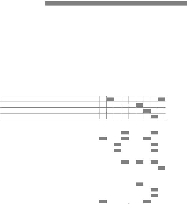
1.4 Application table for probe selection
OPTIFLEX 7200 C/F/S/D 
|
Double rod |
Single rod |
Single rod (segmented) |
Coaxial Ø22 mm |
Coaxial Ø22 mm(segmented) |
Coaxial Ø45 mm |
Double cable |
Single cable |
Reversed interface |
|
|
|
|
|
|
|
|
|
|
Maximum probe length, L
4 m / 13 ft
6 m / 20 ft
14 m / 46 ft
60 m / 197 ft
Liquids
Liquid application |
|
|
|
|
|
|
|
|
|
|
|
|
|
|
|
|
|
|
|
LPG, LNG |
|
1 |
1 |
|
|
|
|
1 |
|
|
|
|
|
|
|
|
|
|
|
Highly viscous liquids |
|
|
|
|
|
|
|
|
|
|
|
|
|
|
|
|
|
|
|
Highly crystallising liquids |
|
|
|
|
|
|
|
|
|
|
|
|
|
|
|
|
|
|
|
Highly corrosive liquids |
|
2 |
|
3 |
|
3 |
|
3 |
|
|
|
|
|
|
|
|
|
|
|
Foam |
|
|
|
|
|
|
|
|
|
|
|
|
|
|
|
|
|
|
|
Water / heavy liquid with low dielectric constant (e.g. water / |
|
|
|
|
|
|
|
|
|
CS2) |
|
|
|
|
|
|
|
|
|
Agitated liquids |
4 |
4 |
4 |
4 |
4 |
4 |
4 |
4 |
4 |
|
|
|
|
|
|
|
|
|
|
Spray in tank |
|
1 |
1 |
|
|
|
|
1 |
|
|
|
|
|
|
|||||
Storage tanks |
|
|
|
|
|
|
|
|
|
|
|
|
|
|
|
|
|
|
|
Installation in bypass chamber or stilling well |
|
|
|
|
|
|
|
|
|
|
|
|
|
|
|
|
|
|
|
Small diameter nozzles and long nozzles |
|
4 |
4 |
|
|
|
|
4 |
|
|
|
|
|
|
|||||
|
|
|
|
|
|
|
|
|
|
J standard J optional U on request
1Install the device in a stilling well or a bypass chamber
2Use a fully TFM-T62 PTFE-coated probe
3Use a probe made of HASTELLOY® C-22®
4Use this probe with an anchor fitting. For more data, refer to the handbook.
1.5Measuring principle
This Guided Radar (TDR) level meter has been developed from a proven technology called Time Domain Reflectometry (TDR).
8 |
www.krohne.com |
07/2019 - 4006447902 - TD OPTIFLEX 7200 R02 en |

OPTIFLEX 7200 C/F/S/D
PRODUCT FEATURES 1
The device transmits low-intensity electromagnetic pulses of approximately one nanosecond width along a rigid or flexible conductor. These pulses move at the speed of light. When the pulses reach the surface of the product to be measured, the pulses are reflected with an intensity that depends on the dielectric constant, εr, of the product (for example, water has a high
dielectric constant and reflects the pulse back to the signal converter at 80% of its original intensity).
The device measures the time from when the pulse is emitted to when it is received: half of this time is equivalent to the distance from the reference point of the device (the flange facing) to the surface of the product. The time value is converted into an output current of 4...20 mA and/or a digital signal.
Dust, foam, vapor, agitated surfaces, boiling surfaces, changes in pressure, changes in temperature and changes in density do not have an effect on device performance.
The illustration that follows shows a snapshot of what a user would see on an oscilloscope, if the level of one product is measured.
Level measurement principle (direct mode)
Figure 1-1: Level measurement principle
1Time 0: The electromagnetic (EM) pulse is transmitted by the converter
2Time 1: The pulse goes down the probe at the speed of light in air, V1
3Time 2: The pulse is reflected
4Time 3: The pulse goes up the probe at speed, V1
5Time 4: The converter receives the pulse and records the signal
6The EM pulse moves at speed, V1
7Transmitted EM pulse
8Half of this time is equivalent to the distance from the reference point of the device (the flange facing) to the surface of the product
9Received EM pulse
Level and interface measurement principle (direct measurement)
The illustration that follows shows a snapshot of what a user would see on an oscilloscope, if the level and/or interface of products are measured.
07/2019 - 4006447902 - TD OPTIFLEX 7200 R02 en |
www.krohne.com |
9 |

1 PRODUCT FEATURES |
OPTIFLEX 7200 C/F/S/D |
|
The dielectric constant of the top liquid must be less than the dielectric constant of the bottom liquid. If not, or if there is too small a difference, the device may not measure correctly.
Figure 1-2: Level and interface measurement principle (2 liquids in the tank)
1Time 0: The electromagnetic (EM) pulse is transmitted by the converter
2Time 1: The pulse goes down the probe at the speed of light in air, V1
3Time 2: Part of the pulse is reflected at the surface of the top liquid, the remaining pulse goes down the probe
4Time 3: Part of the pulse goes up the probe at speed, V1. The remaining pulse goes down the probe at the speed of light in the top product, V2
5Time 4: The converter receives part of the pulse and records the signal. The remaining pulse is reflected at the interface of the 2 liquids
6Time 5: The remaining pulse goes up the probe at speed, V2
7Time 6: The remaining pulse goes up the probe at speed, V1
8Time 7: The converter receives the remaining pulse and records the signal
9The EM pulse moves at speed, V1
10The EM pulse moves at speed, V2
11Transmitted EM pulse
12Received EM pulse (distance to the top liquid)
13Received EM pulse (distance to the interface of 2 liquids)
Level measurement principle (TBF measurement)
If products have a very low dielectric constant (εr <1.6), only a small part of the EM pulse is
reflected at the surface of the product. Most of the pulse is reflected at the probe end. TBF (tank bottom following) mode is used to measure the distance to the product surface.
TBF mode (indirect measurement) compares:
•The time for the pulse to go to the probe end and go back to the converter when the tank is empty.
•The time for the pulse to go to the probe end and go back to the converter when the tank is full or partially filled.
The level of the product in the tank can be calculated from the time difference.
10 |
www.krohne.com |
07/2019 - 4006447902 - TD OPTIFLEX 7200 R02 en |
|
|
TECHNICAL DATA 2 |
|
OPTIFLEX 7200 C/F/S/D |
|
|
|
|
2.1Technical data
•The following data is provided for general applications. If you require data that is more relevant to your specific application, please contact us or your local sales office.
•Additional information (certificates, special tools, software,...) and complete product documentation can be downloaded free of charge from the website (Downloadcenter).
Converter
Measuring system
Application |
Level and interface measurement of liquids and pastes |
|
|
Measuring principle |
TDR (time domain reflectometry) |
|
|
Primary measured values |
Distance and interface distance |
|
|
Secondary values |
Level, interface level, volume and mass |
|
|
Construction |
Compact (C) version: Measuring probe attached directly to the signal converter |
|
Remote (F) version: Measuring probe installed on a tank and connected by a signal |
|
cable (max. length 100 m / 328 ft) to the signal converter |
|
Sensor extension (S) version: Measuring probe installed on a tank and connected by |
|
a coaxial cable (max. length 15 m / 49 ft) to the signal converter |
|
Double sensor extension (D) version: Measuring probe installed on a tank and |
|
connected by a coaxial cable (max. length 15 m / 49 ft) to the probe electronics |
|
housing. The probe electronics housing is connected by a signal cable (max. length |
|
100 m / 328 ft) to the signal converter. |
|
|
Operating conditions
Ambient temperature |
-40…+80°C / -40…+176°F |
|
Integrated LCD display: -20...+60°C / -5...+140°F; if the ambient temperature is not |
|
in these limits, the display switches off. The device continues to operate correctly. |
Storage temperature |
-50…+85°C / -58…+185°F |
|
(min. -40°C / -40°F for devices with the integrated LCD display option) |
Ingress protection |
IEC 60529: IP66 / IP68 (continuous immersion at a depth of 1.5 m for 2 weeks) |
|
|
|
NEMA 250: NEMA type 4X / 6 (housing) and type 6P (probe) |
|
|
Materials
Housing |
Polyester-coated aluminium or stainless steel (1.4404 / 316L) |
|
|
Cable entry |
Plastic; nickel-plated brass, stainless steel |
|
|
Electrical connections
Power supply, output 1 |
Non-Ex / Ex i: |
(4...20 mA/HART output) |
11.5…30 V DC; min./max. value for an output of 22 mA at the terminals |
|
|
|
Ex d: |
|
13.5…34 V DC; min./max. value for an output of 22 mA at the terminals |
Power supply, optional output 2 |
Non-Ex / Ex i: |
(4...20 mA output) |
11.5…30 V DC; min./max. value for an output of 22 mA at the terminals |
|
(additional power supply needed – output only) |
|
Ex d: |
|
11.5…34 V DC; min./max. value for an output of 22 mA at the terminals |
|
(additional power supply needed – output only) |
Power supply, optional input 2 |
Non-Ex / Ex d: |
(switch output - relay) |
11.5…34 V DC / 30 mA |
|
Ex i: |
|
11.5…30 V DC / 30 mA |
07/2019 - 4006447902 - TD OPTIFLEX 7200 R02 en |
www.krohne.com |
11 |

2 TECHNICAL DATA |
|
|
|
|
|
|
OPTIFLEX 7200 C/F/S/D |
|
|||
|
|
|
|
|
|
|
|
|
|
||
Current output load |
|
Non-Ex / Ex i: RL [Ω] ≤ ((Uext -11.5 V)/22 mA). |
|
|
|
|
|
For more data, refer to Minimum power supply voltage on page 24. |
|
||
|
|
|
|
||
|
|
Ex d, output 1: RL [Ω] ≤ ((Uext -13.5 V)/22 mA). |
|
|
|
|
|
For more data, refer to Minimum power supply voltage on page 24. |
|
||
|
|
|
|
||
|
|
Ex d, output 2: RL [Ω] ≤ ((Uext -11.5 V)/22 mA). |
|
|
|
|
|
For more data, refer to Minimum power supply voltage on page 24. |
|
||
|
|
|
|
||
Cable entry |
|
M20×1.5; ½ NPT |
|
|
|
|
|
|
|
||
Cable gland |
|
Standard: none |
|
|
|
|
|
|
|
||
|
|
Options: M20×1.5, others are available on request |
|
|
|
|
|
|
|
||
|
|
Cable diameter, output 1: |
|
|
|
|
|
non-Ex / Ex i: 6...7.5 mm / 0.24...0.30¨; Ex d: 7...10 mm / 0.28...0.39¨; |
|
||
|
|
Cable diameter, output 2: |
|
||
|
|
non-Ex / Ex i: 6...12 mm / 0.24...0.47¨; Ex d: 7...12 mm / 0.28...0.47¨ |
|
||
Signal cable – remote version |
|
None for non-Ex devices (4-wire shielded cable of max. length 100 m / 328 ft to be |
|
|
|
|
|
supplied by the customer). Supplied with all Ex-approved devices. For more data, |
|
||
|
|
refer to the handbook |
|
||
|
|
|
|
||
Cable entry capacity (terminal) |
|
0.5…2.5 mm² |
|
|
|
Input and output |
|
|
|
|
|
|
|
|
|
||
Measured variable |
|
Time between the emitted and received signal |
|
||
|
|
|
|
|
|
Current output / HART® |
|
|
|
|
|
Output 1 signal |
|
4…20 mA HART® or 3.8…20.5 mA acc. to NAMUR NE 43 1 |
|
|
|
|
|
|
|
||
Output 2 signal |
|
4…20 mA or 3.8…20.5 mA acc. to NAMUR NE 43 |
|
|
|
|
|
|
|
||
Resolution |
|
±3 µA |
|
|
|
|
|
|
|
||
Temperature drift (analog) |
|
Typically 50 ppm/K |
|
|
|
|
|
|
|
||
Temperature drift (digital) |
|
Max. ±15 mm for the full temperature range |
|
|
|
|
|
|
|
||
Error signal options |
|
High: 22 mA; Low: 3.6 mA acc. to NAMUR NE 43; Hold (frozen value – not available if |
|
|
|
|
|
the output agrees with NAMUR NE 43 or the device is approved for safety-related |
|
||
|
|
systems (SIL)) |
|
||
|
|
|
|
|
|
Switch output - relay (option) |
|
|
|
|
|
|
|
|
|||
Description |
|
Relay (1 contact, normally open). SIS 2 Sensitive Series (ELESTA GmbH). |
|
|
|
|
|
|
|
||
Maximum switching capacity |
|
48 V AC / 6 A; 24 V DC / 6 A (according to IEC 60947-5-1) |
|
|
|
|
|
|
|
||
Voltage range |
|
Category AC-1: 5...48 V AC / Category DC-1: 2...24 V DC |
|
|
|
|
|
|
|
||
Current range |
|
0.003...6 A |
|
|
|
|
|
|
|
||
Ron-state |
|
< 100 mΩ at 6 V / 100 mA |
|
|
|
Switching capacity range |
|
0.04...288 W (VA) |
|
|
|
Display and user interface |
|
|
|
|
|
|
|
|
|
||
User interface options |
|
LCD display (128 × 64 pixels in 8-step greyscale with 4-button keypad) |
|
||
|
|
|
|
||
Languages |
|
English, German, French, Italian, Spanish, Portuguese, Japanese, Chinese |
|
|
|
|
|
(simplified), Russian, Czech, Polish and Turkish |
|
||
|
|
|
|
|
|
12 |
www.krohne.com |
07/2019 - 4006447902 - TD OPTIFLEX 7200 R02 en |

|
|
TECHNICAL DATA 2 |
|
OPTIFLEX 7200 C/F/S/D |
|
|
|
|
Approvals and certification
CE |
The device meets the essential requirements of the EU Directives. The |
|
|
manufacturer certifies successful testing of the product by applying the CE |
|
|
marking. |
|
|
|
|
|
For more data about the EU Directives and European Standards related to this |
|
|
device, refer to the EU Declaration of Conformity. You can download this document |
|
|
free of charge from the website (Download Center). |
|
|
|
|
Vibration resistance |
Housing: EN 60721-3-4, Category 4M4 |
|
|
(5...8.51 Hz: ±3.5 mm / 8.51...200 Hz: 1g; 15g shock ½sinus: 6 ms) |
|
|
"C" version only: |
|
|
DNVGL-CG-0339, Class A (5...13.2 Hz: ±0.5 mm / 13.2...100 Hz: 0.7g) |
|
|
Refer to "Probe options" in this section for the vibration resistance of probes |
|
Explosion protection |
|
|
|
|
|
ATEX (Ex ia, Ex ia/db or Ex ia/tb) |
Compact version |
|
EU Type Approval |
|
|
II 1/2 G Ex ia IIC T6...T* Ga/Gb; 2 |
||
|
||
|
|
|
|
II 1/2 D Ex ia IIIC T85°C...T*°C Da/Db 3 |
|
|
|
|
|
or... |
|
|
|
|
|
II 1/2 G Ex ia/db IIC T6...T* Ga/Gb; 2 |
|
|
|
|
|
II 1/2 D Ex ia/tb IIIC T85°C...T*°C Da/Db 3 |
|
|
|
|
|
Remote version, converter |
|
|
|
|
|
II 2 (1) G Ex ia [ia Ga] IIC T6...T4 Gb; |
|
|
|
|
|
II 2 (1) D Ex ia [ia Da] IIIC T85°C...T135°C Db |
|
|
or... |
|
|
|
|
|
II 2 (1) G Ex db ia [ia Ga] IIC T6...T4 Gb; |
|
|
|
|
|
II 2 (1) D Ex ia tb [ia Da] IIIC T80°C...T150°C Db |
|
|
|
|
|
Remote version, sensor |
|
|
|
|
|
II 1/2 G Ex ia IIC T6...T* Ga/Gb; 2 |
|
|
|
|
|
II 1/2 D Ex ia IIIC T85°C...T*°C Da/Db 3 |
|
|
|
|
ATEX (Ex ic or Ex ic nA) |
Compact version |
|
Type Approval |
|
|
II 3 G Ex ic IIC T6...T* Gc; 2 |
||
|
||
|
|
|
|
II 3 D Ex ic IIIC T85°C...T*°C Dc 3 |
|
|
|
|
|
or... |
|
|
|
|
|
II 3 G Ex ic nA IIC T6...T* Gc 2 |
|
|
|
|
|
Remote version, converter |
|
|
|
|
|
II 3 G Ex ic [ic] IIC T6...T4 Gc; |
|
|
|
|
|
II 3 D Ex ic [ic] IIIC T85°C...T135°C Dc |
|
|
|
|
|
or... |
|
|
|
|
|
II 3 G Ex ic nA [ic] IIC T6...T4 Gc |
|
|
|
|
|
Remote version, sensor |
|
|
|
|
|
II 3 G Ex ic IIC T6...T* Gc; 2 |
|
|
|
|
|
II 3 D Ex ic IIIC T85°C...T*°C Dc 3 |
|
|
|
07/2019 - 4006447902 - TD OPTIFLEX 7200 R02 en |
www.krohne.com |
13 |

2 TECHNICAL DATA |
|
|
|
|
|
|
|
|
|
|
|
|
OPTIFLEX 7200 C/F/S/D |
|
|||
|
|
|
|
|
|
|
||
|
|
|
|
|
|
|
||
IECEx |
Compact version |
|
|
|
|
|||
|
|
|
|
|||||
|
|
Ex ia IIC T6 T* Ga/Gb; 2... |
||||||
|
|
|
|
|
||||
|
|
Ex ia IIIC T85°C |
...T*°C Da/Db 3 |
|||||
|
|
|
|
|
|
|
|
|
|
|
or... |
|
|
|
|
|
|
|
|
|
|
|
||||
|
|
Ex ia/db IIC T6... |
T* Ga/Gb; 2 |
|||||
|
|
|
|
|
||||
|
|
Ex ia/tb IIIC T85°C... |
T*°C Da/Db 3 |
|||||
|
|
|
|
|
|
|
|
|
|
|
or... |
|
|
|
|
|
|
|
|
|
|
|
|
|||
|
|
Ex ic IIC T6 T* Gc; 2... |
|
|
|
|||
|
|
|
|
|
||||
|
|
Ex ic IIIC T85°C... |
T*°C Dc 3 |
|||||
|
|
|
|
|
|
|
|
|
|
|
or... |
|
|
|
|
|
|
|
|
|
|
|
||||
|
|
Ex ic nA IIC T6... |
T* Gc 2 |
|||||
|
|
|
|
|||||
|
|
Remote version, converter |
||||||
|
|
|
|
|
||||
|
|
Ex ia [ia Ga] IIC T6... |
T4 Gb; |
|||||
|
|
|
|
|
||||
|
|
Ex ia [ia Da] IIIC T85°C |
...T135°C Db |
|||||
|
|
|
|
|
|
|
|
|
|
|
or... |
|
|
|
|
|
|
|
|
|
|
|
||||
|
|
Ex db ia [ia Ga] IIC T6... |
T4 Gb |
|||||
|
|
|
|
|||||
|
|
Ex ia tb [ia Da] IIIC T85°C T135°C Db... |
||||||
|
|
|
|
|
|
|
|
|
|
|
or... |
|
|
|
|
|
|
|
|
|
|
|
|
|
||
|
|
Ex ic [ic] IIC T6... |
T4 Gc |
|
|
|
||
|
|
|
|
|
||||
|
|
Ex ic [ic] IIIC T85°C... |
T135°C Dc |
|||||
|
|
|
|
|
|
|
|
|
|
|
or... |
|
|
|
|
|
|
|
|
|
|
|
||||
|
|
Ex ic nA [ic] IIC T6... |
T4 Gc |
|||||
Remote version, sensor
Ex ia IIC T6...T* Ga/Gb; 2
Ex ia IIIC T85°C...T*°C Da/Db 3
or...
Ex ic IIC T6...T* Gc; 2
Ex ic IIIC T85°C...T*°C Dc 3
14 |
www.krohne.com |
07/2019 - 4006447902 - TD OPTIFLEX 7200 R02 en |

|
|
TECHNICAL DATA 2 |
|
OPTIFLEX 7200 C/F/S/D |
|
|
|
|
cQPSus – Dual Seal-approved NEC 500 and CEC Section 18 and Annex J (Division ratings)
Compact version
IS, Class I, Div 1, GPS ABCD, T6...T*; 2
IS, Class II/III, Div 1, GPS EFG, T85°C...T*°C 3
or...
XP-IS, Class I, Div 1, GPS A (US only) BCD, T6...T*; 2
DIP-IS, Class II/III, Div 1, GPS EFG, T85°C...T*°C 3
or...
NI, Class I, Div 2, GPS ABCD, T6...T*; 2
NI, Class II/III, Div 2, GPS FG, T85°C...T*°C 3
Remote version, converter
IS, Class I, Div 1, GPS ABCD, T6...T4;
IS, Class II/III, Div 1, GPS EFG, T85°C...T135°C
or...
XP-IS, Class I, Div 1, GPS A (US only) BCD, T6...T4;
DIP-IS, Class II/III, Div 1, GPS EFG, T85°C...T135°C
or...
NI, Class I, Div 2, GPS ABCD, T6...T4;
NI, Class II/III, Div 2, GPS FG, T85°C...T135°C
Remote version, sensor
IS, Class I, Div 1, GPS ABCD, T6...T*; 2
IS, Class II/III, Div 1, GPS EFG, T85°C...T*°C 3
or...
NI, Class I, Div 2, GPS ABCD, T6...T*; 2
NI, Class II/III, Div 2, GPS FG, T85°C...T*°C 3
NEC 505 and NEC 506 (Zone ratings)
Compact version
Class I, Zone 0 AEx ia IIC T6...T* Ga; 2
Zone 20, AEx ia IIIC T85°C...T*°C Da 3
or...
Class I, Zone 1 AEx db ia [ia Ga] IIC T6...T* Gb; 2
Zone 21, AEx ia tb [ia Da] IIIC T85°C...T*°C Db 3
Remote version, converter
Class I, Zone 1 AEx ia [ia Ga] IIC T6...T4 Gb;
Zone 21, AEx ia [ia Da] IIIC T85°C...T135°C Db
or...
Class I, Zone 1 AEx db ia [ia Ga] IIC T6...T4 Gb;
Zone 21, AEx ia tb [ia Da] IIIC T85°C...T135°C Db
Remote version, sensor
Class I, Zone 0 AEx ia IIC T6...T* Ga; 2
Zone 20, AEx ia IIIC T85°C...T*°C Da 3
07/2019 - 4006447902 - TD OPTIFLEX 7200 R02 en |
www.krohne.com |
15 |

2 TECHNICAL DATA |
|
|
|
|
|
|
OPTIFLEX 7200 C/F/S/D |
|
|||
|
|
|
|
|
|
|
|
|
|
||
|
|
CEC Section 18 (Zone ratings) |
|
|
|
|
|
|
|
||
|
|
Compact version |
|
|
|
|
|
|
|
||
|
|
Ex ia IIC T6...T* Ga; 2 |
|
|
|
|
|
|
|
||
|
|
Ex ia IIIC T85°C...T*°C Da 3 |
|
|
|
|
|
|
|
||
|
|
or... |
|
|
|
|
|
|
|
||
|
|
Ex db ia [ia Ga] IIC T6...T* Gb; 2 |
|
|
|
|
|
|
|
||
|
|
Ex ia tb [ia Da] IIIC T85°C...T*°C Db 3 |
|
|
|
|
|
|
|
||
|
|
Remote version, converter |
|
|
|
|
|
|
|
||
|
|
Ex ia [ia Ga] IIC T6...T4 Gb; |
|
|
|
|
|
|
|
||
|
|
Ex ia [ia Da] IIIC T85°C...T135°C Db |
|
|
|
|
|
|
|
||
|
|
or... |
|
|
|
|
|
|
|
||
|
|
Ex db ia [ia Ga] IIC T6...T4 Gb; |
|
|
|
|
|
|
|
||
|
|
Ex ia tb [ia Da] IIIC T85°C...T135°C Db |
|
|
|
|
|
|
|
||
|
|
Remote version, sensor |
|
|
|
|
|
|
|
||
|
|
Ex ia IIC T6...T* Ga; 2 |
|
|
|
|
|
|
|
||
|
|
Ex ia IIIC T85°C...T*°C Da 3 |
|
|
|
|
|
|
|
||
NEPSI |
|
Compact version |
|
|
|
|
|
|
|
||
|
|
Ex ia IIC T*~T6 Ga/Gb; 2 |
|
|
|
|
|
|
|
||
|
|
Ex iaD 20/21 T85~T** 3 |
|
|
|
|
|
|
|
||
|
|
or... |
|
|
|
|
|
|
|
||
|
|
Ex ia/d IIC T*~T6 Ga/Gb; 2 |
|
|
|
|
|
|
|
||
|
|
Ex iaD 20 tD A21 IP6X T85°C~T*°C 3 |
|
|
|
|
|
|
|
||
|
|
Remote version, converter |
|
|
|
|
|
|
|
||
|
|
Ex ia [ia Ga] IIC T4~T6 Gb; |
|
|
|
|
|
|
|
||
|
|
Ex iaD [iaD 20] 21 T85~T135 |
|
|
|
|
|
|
|
||
|
|
or... |
|
|
|
|
|
|
|
||
|
|
Ex d ia [ia Ga] IIC T4~T6 Gb; |
|
|
|
|
|
|
|
||
|
|
Ex iaD 21 tD A21 [iaD 20] IP6X T85°C~T135°C |
|
|
|
|
|
Remote version, sensor |
|
|
|
|
|
|
|
||
|
|
Ex ia IIC T*~T6 Ga/Gb; 2 |
|
|
|
|
|
|
|
||
|
|
Ex iaD 20/21 T85~T* 3 |
|
|
|
|
|
|
|
|
|
16 |
www.krohne.com |
07/2019 - 4006447902 - TD OPTIFLEX 7200 R02 en |

|
|
TECHNICAL DATA 2 |
|
OPTIFLEX 7200 C/F/S/D |
|
|
|
|
EAC-EX |
Compact version |
|
(pending) |
|
|
Ga/Gb Ex ia IIC T6...T* X; 2 |
||
|
||
|
|
|
|
Da/Db Ex ia IIIC T85°C…T*°C X 3 |
|
|
|
|
|
or... |
|
|
|
|
|
Ga/Gb Ex ia/db IIC T6...T* X; 2 |
|
|
|
|
|
Da/Db Ex ia/tb IIIC T85°C…T*°C X 3 |
|
|
|
|
|
Remote version, converter |
|
|
|
|
|
1Ex ia [ia Ga] IIC T6...T4 Gb X; |
|
|
|
|
|
Ex ia [ia Da] IIIC T85°C...T135°C Db X |
|
|
|
|
|
or... |
|
|
|
|
|
1Ex db ia [ia Ga] IIC T6...T4 Gb X; |
|
|
|
|
|
Ex ia tb [ia Da] IIIC T85°C...T135°C Db X |
|
|
|
|
|
Remote version, sensor |
|
|
|
|
|
Ga/Gb Ex ia IIC T6...T* X; 2 |
|
|
|
|
|
Da/Db Ex ia IIIC T85°C…T*°C X 3 |
|
|
|
|
Other standards and approvals |
|
|
|
|
|
SIL |
C (Compact) and S (Sensor Extension) versions only: SIL 2/3 (SIL3: 1oo2 |
|
|
architecture is necessary for homogeneous redundancy) – certified according to all |
|
|
the requirements in EN 61508 (Full Assessment) and for high/low continuous |
|
|
demand mode operation. HFT=0, SFF=93% (for non-Ex / Ex i devices with one |
|
|
output), 94% (for non-Ex / Ex i devices with two outputs) or 95% (for Ex d devices), |
|
|
type B device |
|
|
|
|
EMC |
Electromagnetic Compatibility (EMC) directive. The device agrees with this directive |
|
|
and its related standard if the device has a single probe that is installed in a metallic |
|
|
tank. |
|
|
SIL 2-approved devices agree with EN 61326-3-1 and EN 61326-3-2. |
|
|
|
|
NAMUR |
NAMUR NE 21 Electromagnetic Compatibility (EMC) of Industrial Process and |
|
|
Laboratory Control Equipment |
|
|
|
|
|
NAMUR NE 43 Standardization of the Signal Level for the Failure Information of |
|
|
Digital Transmitters |
|
|
|
|
|
NAMUR NE 53 Software and Hardware of Field Devices and Signal Processing |
|
|
Devices with Digital Electronics |
|
|
|
|
|
NAMUR NE 107 Self-Monitoring and Diagnosis of Field Devices |
|
|
|
|
Conformity to construction codes |
On request (for equipment used in the oil and gas industries): |
|
|
NACE MR0175 (ISO 15156); NACE MR0103 (ISO 17945) |
|
|
|
1HART® is a registered trademark of the FieldComm Group™
2If the device has a ceramic process seal system and a Kalrez® gasket, then T*= T2. For all other versions, T* = T3.
3If the device has a ceramic process seal system and a Kalrez® gasket, then T*°C = T250°C and T** = T250. If the device has a ceramic process and an FPM/FKM gasket, then T*°C = T200°C and T** = T200. For all other versions, T*°C = T150°C and T** = T150.
07/2019 - 4006447902 - TD OPTIFLEX 7200 R02 en |
www.krohne.com |
17 |

2 TECHNICAL DATA |
|
|
|
|
|
|
|
|
|
|
|
OPTIFLEX 7200 C/F/S/D |
|
||||
Probe options |
|
|
|
|
|
|
|
|
|
|
|
|
|
|
|
|
|
|
|
|
Single rod |
Single rod |
Single cable |
|
|
|
|
|
|
Ø8 mm / 0.39¨ |
Ø10 mm / 0.32¨ |
Ø4 mm / 0.16¨ |
|
||
|
|
|
|
|
|
|
|
|
|
|
|
Single-piece |
Segmented |
Single-piece, |
|
|
|
|
|
|
|
|
fully TFM-T62 |
|
|
|
|
|
|
|
|
PTFE coated |
|
|
|
|
|
|
|
|
|
|
|
|
Measuring system |
|
|
|
|
|
|
|
|
|
|
|
|
|
|
|
|
|
Application |
|
Liquids |
|
|
|
|
|
|
|
|
|
|
|
|
|
||
Measuring range |
|
0.6...4 m / |
0.6...6 m / |
0.6...4 m / |
1...60 m / |
|
|
|
|
|
3.28...13.12 ft |
3.28...19.69 ft |
3.28...13.12 ft |
3.28...196.85 ft |
|
||
Dead zone |
|
This depends on the type of probe. For more data, refer to Measurement limits on |
|
|||||
|
|
page 28. |
|
|
|
|
|
|
Measuring accuracy |
|
|
|
|
|
|
|
|
|
|
|
|
|
|
|
|
|
Accuracy (in direct mode) |
|
Standard |
|
|
|
|
|
|
|
|
±2 mm / ±0.08¨, when distance ≤ 10 m / 33 ft; |
|
|
|
|||
|
|
±0.02% of measured distance, when distance > 10 m / 33 ft |
|
|
|
|||
|
|
Interface |
|
|
|
|
|
|
|
|
±5 mm / ±0.2¨, when distance ≤ 10 m / 33 ft; |
|
|
|
|||
|
|
±0.05% of measured distance, when distance > 10 m / 33 ft |
|
|
|
|||
Accuracy (in TBF mode) |
|
±20 mm / ±0.8¨ |
|
|
|
|
|
|
|
|
|
|
|
|
|
|
|
Minimum layer (interface) |
|
50 mm / 2¨ |
|
|
|
|
|
|
|
|
|
|
|
|
|
|
|
Resolution |
|
0.1 mm / 0.004¨ |
|
|
|
|
|
|
|
|
|
|
|
|
|
|
|
Repeatability |
|
±1 mm / ±0.04¨ |
|
|
|
|
|
|
|
|
|
|
|
|
|
||
Maximum rate of change at 4 mA |
|
100 m/min / 328 ft/min |
|
|
|
|
||
|
|
|
|
|
|
|
||
Reference conditions acc. to EN 61298-1 |
|
|
|
|
|
|||
|
|
|
|
|
|
|
||
Temperature |
|
+15...+25°C / +59...+77°F |
|
|
|
|
||
|
|
|
|
|
|
|||
Pressure |
|
1013 mbara ±50 mbar / 14.69 psia ±0.73 psi |
|
|
|
|||
|
|
|
|
|
|
|
|
|
Relative air humidity (RH) |
|
60% ±15% |
|
|
|
|
|
|
Target |
|
Metal plate |
|
|
Water |
|
|
|
Operating conditions |
|
|
|
|
|
|
|
|
|
|
|
|
|
|
|
||
Min./Max. temperature at the |
|
-50…+250°C / |
|
-50…+150°C / |
-50…+250°C / |
|
||
process connection 1 |
|
-58…+482°F |
|
-58…+302°F |
-58…+482°F |
|
||
Pressure |
|
Single PTFE process seal system or fully TFM-T62 PTFE-coated: |
|
|||||
|
|
-1…40 barg / -14.5…580 psig |
|
|
|
|
||
|
|
Single ceramic process seal system: |
— |
Single ceramic |
|
|
||
|
|
-1…100 barg / -14.5…1450 psig |
|
process seal |
|
|||
|
|
|
|
|
|
system |
|
|
|
|
|
|
|
|
-1…100 barg / |
|
|
|
|
|
|
|
|
-14.5…1450 psig |
|
|
Viscosity (liquids only) |
|
10000 mPa·s / 10000 cP |
|
|
|
|
||
|
|
|
|
|||||
Dielectric constant |
|
≥ 1.6 in direct mode (interface: εr(interface) >> εr(level)²); ≥ 1.1 in TBF mode |
|
|
||||
18 |
www.krohne.com |
07/2019 - 4006447902 - TD OPTIFLEX 7200 R02 en |

|
|
TECHNICAL DATA 2 |
|
OPTIFLEX 7200 C/F/S/D |
|
|
|
|
|
Single rod |
|
Single rod |
Single cable |
|
|
Ø8 mm / 0.39¨ |
|
Ø10 mm / 0.32¨ |
Ø4 mm / 0.16¨ |
|
|
|
|
|
|
|
|
Single-piece |
Segmented |
|
Single-piece, |
|
|
|
|
|
fully TFM-T62 |
|
|
|
|
|
PTFE coated |
|
|
|
|
|
|
|
Vibration resistance |
EN 60721-3-4, Category 4M3 (5...8.22 Hz: ±0.75 mm / |
EN 60721-3-4, |
|||
|
8.22...200 Hz:0.2g; 5g shock ½sinus: 6 ms) |
|
Category 4M4 |
||
|
DNVGL-CG-0339, Class A (5...13.2 Hz: ±0.5 mm / 13.2...100 Hz: |
(5...8.51 Hz: |
|||
|
0.7g) 2 |
|
|
|
±3.5mm / |
|
|
|
|
|
8.51...200 Hz: 1g; |
|
|
|
|
|
15g shock ½sinus: |
|
|
|
|
|
6 ms) |
|
|
|
|
|
DNVGL-CG-0339, |
|
|
|
|
|
Class A |
|
|
|
|
|
(5...13.2 Hz: |
|
|
|
|
|
±0.5 mm / |
|
|
|
|
|
13.2...100 Hz: 0.7g) |
Materials
Probe |
Stainless steel |
Stainless steel |
TFM-T62 |
Stainless steel |
|
(1.4404 / 316L); |
(1.4404 / 316L) |
PTFE-coated |
(1.4401 / 316) 4 |
|
HASTELLOY® |
|
stainless steel |
|
|
C-22® (2.4602) 3 |
|
(1.4404 / 316L) |
|
Gasket (process seal) |
Single PTFE process seal system: |
None |
Single ceramic |
|
|
FKM/FPM, Kalrez® 6375, EPDM 5 |
|
process seal |
|
|
|
|
|
system FKM/FPM, |
|
|
|
|
Kalrez® 6375, |
|
|
|
|
EPDM 5 |
|
Single ceramic process seal system: |
None |
Single ceramic |
|
|
FKM/FPM, Kalrez® 7075, EPDM 5 |
|
process seal |
|
|
|
|
|
system: FKM/FPM, |
|
|
|
|
Kalrez® 7075, |
|
|
|
|
EPDM 5 |
Process connection |
Stainless steel |
Stainless steel |
TFM-T62 |
Stainless steel |
|
(1.4404 / 316L); |
(1.4404 / 316L) |
PTFE-coated |
(1.4404 / 316L) 4 |
|
HASTELLOY® |
|
stainless steel |
|
|
C-22® (2.4602) 3 |
|
(1.4404 / 316L) |
|
Other wetted parts |
PTFE |
|
|
|
|
|
|
|
|
Process connections
Thread |
For more data on options, refer to Order code on page 66 |
|
|
Flange |
For more data on options, refer to Order code on page 66 |
|
|
1Also depends on the temperature limits of the gasket material. Refer to "Materials" in this table and the "Process seal technical data" table.
2The DNV vibration test does not include the "S" version of the device
3HASTELLOY® is a registered trademark of Haynes International, Inc.
4HASTELLOY® C-22® (2.4602) is available on request. HASTELLOY® is a registered trademark of Haynes International, Inc.
5For more data, refer to the "Process seal technical data" table in this section. Kalrez® is a registered trademark of DuPont Performance Elastomers L.L.C.
07/2019 - 4006447902 - TD OPTIFLEX 7200 R02 en |
www.krohne.com |
19 |

2 TECHNICAL DATA |
|
|
|
|
|
|
|
|
|
|
OPTIFLEX 7200 C/F/S/D |
|
|||
|
|
|
|
|
|
|
|
|
|
|
|
|
|
|
|
|
|
|
Double cable |
Double rod |
Reversed interface |
|
|
|
|
|
Ø4 mm / 0.16¨ |
Ø8 mm / 0.32¨) |
Ø10 mm / 0.39¨ |
|
|
Measuring system |
|
|
|
|
|
|
|
|
|
|
|
|
|
|
|
Application |
|
Liquids |
|
|
|
|
|
|
|
|
|
|
|
||
Measuring range |
|
1...14 m / 3.28...45.93 ft |
0.6...4 m / 1.97...13.12 ft |
1...4 m / 3.28...13.12 ft |
|
|
|
|
|
|
|
|
|
||
Dead zone |
|
This depends on the type of probe. For more data, refer to Measurement limits on |
|
||||
|
|
page 28. |
|
|
|
|
|
Measuring accuracy |
|
|
|
|
|
|
|
|
|
|
|
|
|
|
|
Accuracy (in direct mode) |
|
Standard |
|
|
|
|
|
|
|
±2 mm / ±0.08¨, when distance ≤ 10 m / 33 ft; |
|
|
|
||
|
|
±0.02% of measured distance, when distance > 10 m / 33 ft |
|
||||
|
|
Interface |
|
|
|
|
|
|
|
±5 mm / ±0.2¨, when distance ≤ 10 m / 33 ft; |
|
|
|
||
|
|
±0.05% of measured distance, when distance > 10 m / 33 ft |
|
||||
Accuracy (in TBF mode) |
|
±20 mm / ±0.8¨ |
|
|
|
|
|
|
|
|
|
|
|
|
|
Resolution |
|
0.1 mm / 0.004¨ |
|
|
|
|
|
|
|
|
|
|
|
|
|
Repeatability |
|
±1 mm / ±0.04¨ |
|
|
|
|
|
|
|
|
|
|
|
|
|
Maximum rate of change at 4 mA |
|
100 m/min / 328 ft/min |
|
|
|
|
|
|
|
|
|
|
|
||
Reference conditions acc. to EN 61298-1 |
|
|
|
|
|||
|
|
|
|
|
|
||
Temperature |
|
+15...+25°C / +59...+77°F |
|
|
|
|
|
|
|
|
|
|
|
||
Pressure |
|
1013 mbara ±50 mbar / 14.69 psia ±0.73 psi |
|
|
|
||
|
|
|
|
|
|
|
|
Relative air humidity (RH) |
|
60% ±15% |
|
|
|
|
|
|
|
|
|
|
|
|
|
Target |
|
Metal plate |
|
|
|
|
|
Operating conditions |
|
|
|
|
|
|
|
|
|
|
|
|
|
||
Min./Max. temperature at the |
|
-50…+200°C / |
-50…+250°C / |
-50…+150°C / |
|
||
process connection 1 |
|
-58…+392°F |
-58…+482°F |
-58…+302°F |
|
||
Pressure |
|
Single PTFE process seal system: |
|
|
|
||
|
|
-1…40 barg / -14.5…580 psig |
|
|
|
||
|
|
Single ceramic process seal system: |
— |
|
|
||
|
|
-1…100 barg / -14.5…1450 psig |
|
|
|
||
Viscosity (liquids only) |
|
5000 mPa·s / 5000 cP |
|
|
|
|
|
|
|
|
|
|
|
||
Dielectric constant |
|
≥ 1.4 in direct mode (interface: εr(interface) >> εr(level)²) |
|
|
|
||
|
|
≥ 1.1 in TBF mode |
|
|
|
|
|
|
|
|
|
|
|
||
Vibration resistance |
|
EN 60721-3-4, Category |
EN 60721-3-4, Category |
EN 60721-3-4, Category |
|
|
|
|
|
4M4 (5...8.51 Hz: |
4M3 (5...8.22 Hz: |
4M4 (5...8.51 Hz: |
|
||
|
|
±3.5mm / 8.51...200 Hz: |
±0.75 mm / |
±3.5mm / 8.51...200 Hz: |
|
||
|
|
1g; 15g shock ½sinus: |
8.22...200 Hz:0.2g; 5g |
1g; 15g shock ½sinus: |
|
||
|
|
6 ms) |
shock ½sinus: 6 ms) |
6 ms) |
|
||
|
|
DNVGL-CG-0339, Class A |
DNVGL-CG-0339, Class A |
DNVGL-CG-0339, Class A |
|
||
|
|
(5...13.2 Hz: ±0.5 mm / |
(5...13.2 Hz: ±0.5 mm / |
(5...13.2 Hz: ±0.5 mm / |
|
||
|
|
13.2...100 Hz: 0.7g) 2 |
13.2...100 Hz: 0.7g) 2 |
13.2...100 Hz: 0.7g) 2 |
|
||
Materials |
|
|
|
|
|
|
|
|
|
|
|
|
|
||
Probe |
|
Stainless steel |
Stainless steel |
Stainless steel |
|
||
|
|
(1.4401 / 316) |
(1.4404 / 316L) |
(1.4404 / 316L) 3 |
|
||
|
|
|
|
|
|
||
Spacers |
|
FEP |
PTFE |
PTFE |
|
|
|
|
|
|
|
|
|
||
Gasket (process seal) |
|
Single PTFE process seal system: FKM/FPM, Kalrez® 6375, EPDM 4 |
|
||||
|
|
|
|
||||
|
|
Single ceramic process seal system FKM/FPM, Kalrez® 7075, EPDM 4 |
|
|
|||
|
|
|
|
|
|
|
|
20 |
www.krohne.com |
07/2019 - 4006447902 - TD OPTIFLEX 7200 R02 en |
|
|
TECHNICAL DATA 2 |
|
OPTIFLEX 7200 C/F/S/D |
|
|
|
|
|
Double cable |
|
Double rod |
Reversed interface |
|
Ø4 mm / 0.16¨ |
|
Ø8 mm / 0.32¨) |
Ø10 mm / 0.39¨ |
|
|
|
|
|
Process connection |
Stainless steel (1.4404 / 316L) |
|
Stainless steel |
|
|
|
|
|
(1.4404 / 316L) 5 |
|
|
|
|
|
Other wetted parts |
PTFE |
|
|
|
|
|
|
|
|
Process connections
Thread |
For more data on options, refer to Order code on page 66 |
|
|
Flange |
For more data on options, refer to Order code on page 66 |
|
|
1Also depends on the temperature limits of the gasket material. Refer to "Materials" in this table and the "Process seal technical data" table.
2The DNV vibration test does not include the "S" version of the device
3HASTELLOY® C-22® (2.4602) is available on request. HASTELLOY® is a registered trademark of Haynes International, Inc.
4For more data, refer to the "Process seal technical data" table in this section. Kalrez® is a registered trademark of DuPont Performance Elastomers L.L.C.
5HASTELLOY® C-22® (2.4602) is available on request. HASTELLOY® is a registered trademark of Haynes International, Inc..
|
|
Coaxial |
|
|
|
|
|
|
Ø22 mm / 0.87¨ |
Ø42 mm / 1.65¨ |
|
|
|
|
|
|
Single-piece |
Segmented |
Single-piece |
|
|
|
|
Measuring system
Application |
Liquids |
|
|
|
|
Measuring range |
0.3...6 m / 0.98...19.69 ft |
0.6...6 m / 1.97...19.69 ft |
|
|
|
Dead zone |
This depends on the type of probe. For more data, refer to Measurement limits on |
|
|
page 28. |
|
|
|
|
Measuring accuracy
Accuracy (in direct mode) |
Standard |
|
±2 mm / ±0.08¨, when distance ≤ 10 m / 33 ft; |
|
±0.02% of measured distance, when distance > 10 m / 33 ft |
|
Interface |
|
±5 mm / ±0.2¨, when distance ≤ 10 m / 33 ft; |
|
±0.05% of measured distance, when distance > 10 m / 33 ft |
Accuracy (in TBF mode) |
±20 mm / ±0.8¨ |
|
|
Resolution |
0.1 mm / 0.004¨ |
|
|
Repeatability |
±1 mm / ±0.04¨ |
|
|
Maximum rate of change at 4 mA |
100 m/min / 328 ft/min |
|
|
Reference conditions acc. to EN 61298-1 |
|
|
|
Temperature |
+15...+25°C / +59...+77°F |
|
|
Pressure |
1013 mbara ±50 mbar / 14.69 psia ±0.73 psi |
|
|
Relative air humidity (RH) |
60% ±15% |
|
|
Target |
Water |
|
|
Operating conditions
Min./Max. temperature at the |
-50…+250°C / -58…+482°F |
process connection 1 |
|
|
|
07/2019 - 4006447902 - TD OPTIFLEX 7200 R02 en |
www.krohne.com |
21 |

2 TECHNICAL DATA |
|
|
|
|
|
|
|
|
|
|
|
|
OPTIFLEX 7200 C/F/S/D |
|
|||
|
|
|
|
|
|
|
|
|
|
|
|
|
|
|
|
|
|
|
|
|
|
Coaxial |
|
|
|
|
|
|
|
|
|
|
|||
|
|
|
Ø22 mm / 0.87¨ |
|
Ø42 mm / 1.65¨ |
|
|
|
|
|
|
|
|
|
|
|
|
|
|
|
Single-piece |
Segmented |
|
Single-piece |
|
|
|
|
|
|
|
|
|
|
|
Pressure |
|
Single PTFE process seal system: |
|
|
|
|||
|
|
-1…40 barg / -14.5…580 psig |
|
|
|
|||
|
|
Single ceramic process seal system: |
|
|
|
|||
|
|
-1…100 barg / -14.5…1450 psig |
|
|
|
|||
Viscosity (liquids only) |
|
500 mPa·s / 500 cP |
|
|
2000 mPa·s / 2000 cP |
|
|
|
|
|
|
|
|
|
|
||
Dielectric constant |
|
≥ 1.3 in direct mode (interface: εr(interface) >> εr(level)²) |
|
|
|
|||
|
|
≥ 1.1 in TBF mode |
|
|
|
|
|
|
|
|
|
|
|
|
|
||
Vibration resistance |
|
EN 60721-3-4, Category |
EN 60721-3-4, Category |
|
EN 60721-3-4, Category |
|
|
|
|
|
4M4 (5...8.51 Hz: |
4M3 (5...8.22 Hz: |
|
4M4 (5...8.51 Hz: |
|
||
|
|
±3.5mm / 8.51...200 Hz: |
±0.75 mm / |
|
±3.5mm / 8.51...200 Hz: |
|
||
|
|
1g; 15g shock ½sinus: |
8.22...200 Hz:0.2g; 5g |
|
1g; 15g shock ½sinus: |
|
||
|
|
6 ms) |
shock ½sinus: 6 ms) |
|
6 ms) |
|
||
|
|
DNVGL-CG-0339, Class A |
DNVGL-CG-0339, Class A |
|
DNVGL-CG-0339, Class A |
|
||
|
|
(5...13.2 Hz: ±0.5 mm / |
(5...13.2 Hz: ±0.5 mm / |
|
(5...13.2 Hz: ±0.5 mm / |
|
||
|
|
13.2...100 Hz: 0.7g) 2 |
13.2...100 Hz: 0.7g) |
|
13.2...100 Hz: 0.7g) |
|
||
Materials |
|
|
|
|
|
|
|
|
|
|
|
|
|
|
|
||
Probe |
|
Stainless steel |
Stainless steel |
|
Stainless steel |
|
||
|
|
(1.4404 / 316L); |
(1.4404 / 316L) |
|
(1.4404 / 316L); |
|
||
|
|
HASTELLOY® C-22® |
|
|
HASTELLOY® C-22® |
|
||
|
|
(2.4602) |
|
|
(2.4602) 3 |
|
|
|
Spacers |
|
PTFE |
PTFE |
|
PTFE (<250°C / 482°F) |
|
|
|
|
|
|
|
|
|
|||
Gasket (process seal) |
|
Single PTFE process seal system: FKM/FPM, Kalrez® 6375, EPDM 4 |
|
|||||
|
|
|
|
|||||
|
|
Single ceramic process seal system FKM/FPM, Kalrez® 7075, EPDM 4 |
|
|
||||
|
|
|
|
|
|
|
||
Process connection |
|
Stainless steel |
Stainless steel |
|
Stainless steel |
|
|
|
|
|
(1.4404 / 316L); |
(1.4404 / 316L) |
|
(1.4404 / 316L); |
|
||
|
|
HASTELLOY® |
|
|
HASTELLOY® |
|
||
|
|
C-22® (2.4602) 3 |
|
|
C-22® (2.4602) 3 |
|
||
Other wetted parts |
|
PTFE |
|
|
|
|
|
|
Process connections |
|
|
|
|
|
|
|
|
|
|
|
|
|
|
|
|
|
Thread |
|
For more data on options, refer to Order code on page 66 |
|
|
|
|||
|
|
|
|
|
|
|||
Flange |
|
For more data on options, refer to Order code on page 66 |
|
|
|
|||
|
|
|
|
|
|
|
|
|
1Also depends on the temperature limits of the gasket material. Refer to "Materials" in this table and the "Process seal technical data" table.
2The DNV vibration test does not include the "S" version of the device
3HASTELLOY® is a registered trademark of Haynes International, Inc.
4For more data, refer to the "Process seal technical data" table in this section. Kalrez® is a registered trademark of DuPont Performance Elastomers L.L.C.
22 |
www.krohne.com |
07/2019 - 4006447902 - TD OPTIFLEX 7200 R02 en |

|
|
TECHNICAL DATA 2 |
|
OPTIFLEX 7200 C/F/S/D |
|
|
|
|
Process seal technical data
Sealing system |
Process seal |
Process pressure range |
Process connection temperature |
|||
|
material |
|
|
range |
|
|
|
|
|
|
|
|
|
|
|
[barg] |
[psig] |
[°C] |
|
[°F] |
|
|
|
|
|
|
|
Single (PTFE) |
FKM/FPM |
-1...40 |
-14.5...580 |
-40...+150 |
|
-40...+302 |
|
|
|
|
|
|
|
|
Kalrez® 6375 |
|
|
-20...+150 |
|
-4...+302 |
|
|
|
|
|
|
|
|
EPDM |
|
|
-50...+150 |
|
-58...+302 |
|
|
|
|
|
|
|
|
TFM-T62 |
|
|
-50...+150 |
|
-58...+302 |
|
PTFE-coated |
|
|
|
|
|
|
|
|
|
|
|
|
Single (Ceramic) 1 |
FKM/FPM |
-1...100 |
-14.5...1450 |
-40...+200 |
|
-40...+392 |
|
|
|
|
|
|
|
|
Kalrez® 7075 |
|
|
-20...+250 |
|
-4...+482 |
|
|
|
|
|
|
|
|
EPDM |
|
|
-50...+150 |
|
-58...+302 |
|
|
|
|
|
|
|
1 This includes a temperature extension
Process connection options: flange facing finish
Type (flange facing) |
Flange facing finish, Ra (min...max) |
|
|
[µm] |
[µin – AARH] |
|
|
|
EN 1092-1
B1 or E |
3.2…12.5 |
125…500 |
|
|
|
ASME B16.5
RF or FF |
3.2...6.3 |
125...250 |
|
|
|
RJ |
≤ 1.6 |
≤ 63 |
|
|
|
JIS B2220
RF |
3.2...6.3 |
125...250 |
|
|
|
07/2019 - 4006447902 - TD OPTIFLEX 7200 R02 en |
www.krohne.com |
23 |
 Loading...