


 OPTISONIC 3400 Quick Start
Multi purpose, all-round, ultrasonic flowmeter for liquids in all industrial processes
ER 2.2.1_
© KROHNE 11/2013 - QS OPTISONIC 3400_4002741202_R02-en

|
CONTENTS |
OPTISONIC 3400 |
|
|
|
||
|
|
|
|
1 |
Safety instructions |
4 |
||
|
|
|
||
2 |
Installation |
5 |
||
|
|
|
|
|
|
2.1 |
Scope of delivery............................................................................................................... |
5 |
|
|
2.2 |
Device description ............................................................................................................ |
6 |
|
|
2.3 |
Nameplates ...................................................................................................................... |
7 |
|
|
2.3.1 Example of nameplate for the compact version .................................................................... |
7 |
||
|
2.3.2 Nameplate for the measuring sensor (field version)............................................................. |
8 |
||
|
2.3.3 Examples of nameplates on the signal converter (field version) .......................................... |
8 |
||
|
2.4 |
Storage ........................................................................................................................... |
10 |
|
|
2.5 |
Transport ........................................................................................................................ |
10 |
|
|
2.6 |
Pre-installation requirements ....................................................................................... |
11 |
|
|
2.7 |
General requirements .................................................................................................... |
11 |
|
|
2.7.1 Vibration ................................................................................................................................ |
11 |
||
|
2.8 |
Installation conditions .................................................................................................... |
12 |
|
|
2.8.1 Inlet and outlet ...................................................................................................................... |
12 |
||
|
2.8.2 Bends in 2 or 3 dimensions................................................................................................... |
12 |
||
|
2.8.3 T-section ............................................................................................................................... |
12 |
||
|
2.9 |
Bends .............................................................................................................................. |
13 |
|
|
2.10 |
Open feed or discharge ................................................................................................ |
13 |
|
|
2.11 |
Position of pump........................................................................................................... |
14 |
|
|
2.12 |
Control valve................................................................................................................. |
14 |
|
|
2.13 |
Down going pipeline over 5 m /16 ft length ................................................................. |
15 |
|
|
2.14 |
Insulation ...................................................................................................................... |
15 |
|
|
2.15 |
Mounting ....................................................................................................................... |
16 |
|
|
2.16 |
Flange deviation............................................................................................................ |
16 |
|
|
2.17 |
Mounting position ......................................................................................................... |
16 |
|
|
2.18 |
Mounting the field housing, remote version ................................................................ |
17 |
|
|
2.18.1 Pipe mounting ..................................................................................................................... |
17 |
||
|
2.18.2 Turning the display of the field housing version ................................................................ |
18 |
||
3 Electrical connections |
19 |
|||
|
|
|
|
|
|
3.1 |
Safety instructions.......................................................................................................... |
19 |
|
|
3.2 |
Signal cable (remote versions only)............................................................................... |
19 |
|
|
3.3 |
Power supply .................................................................................................................. |
21 |
|
|
3.4 |
Laying electrical cables correctly .................................................................................. |
22 |
|
|
3.5 |
Inputs and outputs, overview ......................................................................................... |
23 |
|
|
3.5.1 Combinations of the inputs/outputs (I/Os) ........................................................................... |
23 |
||
|
3.5.2 Description of the CG number .............................................................................................. |
24 |
||
|
3.5.3 Fixed, non-alterable input/output versions.......................................................................... |
25 |
||
|
3.5.4 Alterable input/output versions............................................................................................ |
26 |
||
4 Technical data |
27 |
|||
|
|
|
|
|
|
4.1 |
Dimensions and weights ................................................................................................ |
27 |
|
|
4.2 |
Variants........................................................................................................................... |
27 |
|
|
4.3 |
Standard flow sensor DN300 and smaller..................................................................... |
28 |
|
|
4.4 |
Flow sensor variant DN350 and larger ......................................................................... |
32 |
|
2 |
www.krohne.com |
11/2013 - QS OPTISONIC 3400_4002741202_R02-en |

|
|
CONTENTS |
|
|
OPTISONIC 3400 |
|
|
|
|
|
|
4.5 |
Standard flow sensor DN350 and larger ....................................................................... |
33 |
4.6 |
Signal converter housing ............................................................................................... |
35 |
5 Notes |
|
36 |
11/2013 - QS OPTISONIC 3400_4002741202_R02-en |
www.krohne.com |
3 |

1 SAFETY INSTRUCTIONS |
|
|
OPTISONIC 3400 |
|
|
|
|
|
Warnings and symbols used
DANGER!
This information refers to the immediate danger when working with electricity.
DANGER!
These warnings must be observed without fail. Even partial disregard of this warning can lead to serious health problems and even death. There is also the risk of seriously damaging the device or parts of the operator's plant.
WARNING!
Disregarding this safety warning, even if only in part, poses the risk of serious health problems. There is also the risk of damaging the device or parts of the operator's plant.
CAUTION!
Disregarding these instructions can result in damage to the device or to parts of the operator's plant.
INFORMATION!
These instructions contain important information for the handling of the device.
HANDLING
•This symbol designates all instructions for actions to be carried out by the operator in the specified sequence.
iRESULT
This symbol refers to all important consequences of the previous actions.
Safety instructions for the operator
CAUTION!
Installation, assembly, start-up and maintenance may only be performed by appropriately trained personnel. The regional occupational health and safety directives must always be observed.
LEGAL NOTICE!
The responsibility as to the suitability and intended use of this device rests solely with the user. The supplier assumes no responsibility in the event of improper use by the customer. Improper installation and operation may lead to loss of warranty. In addition, the "Terms and Conditions of Sale" apply which form the basis of the purchase contract.
INFORMATION!
•Further information can be found on the supplied CD-ROM in the manual, on the data sheet, in special manuals, certificates and on the manufacturer's website.
•If you need to return the device to the manufacturer or supplier, please fill out the form contained on the CD-ROM and send it with the device. Unfortunately, the manufacturer cannot repair or inspect the device without the completed form.
4 |
www.krohne.com |
11/2013 - QS OPTISONIC 3400_4002741202_R02-en |
|
|
INSTALLATION 2 |
|
OPTISONIC 3400 |
|
|
|
|
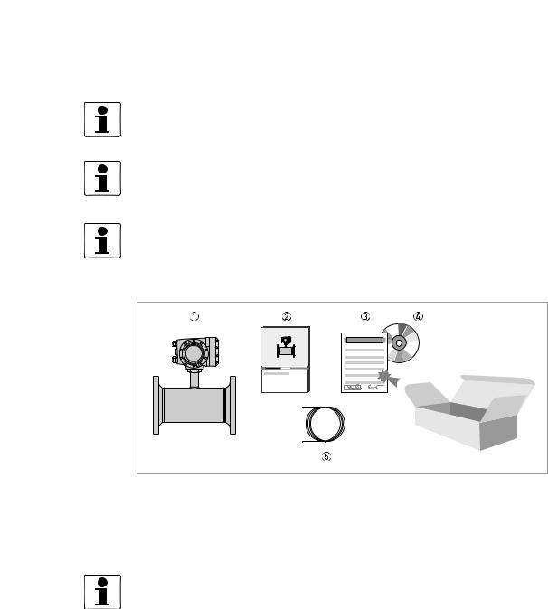
2.1 Scope of delivery
INFORMATION!
Do a check of the packing list to make sure that you have all the elements given in the order.
INFORMATION!
Inspect the cartons carefully for damages or signs of rough handling. Report damage to the carrier and to the local office of the manufacturer.
INFORMATION!
The device will arrive in two cartons. One carton contains the converter and one carton contains the sensor.
Figure 2-1: Scope of delivery - compact version
1Ordered flowmeter
2Product documentation
3Factory calibration certificate
4CD-ROM with product documentation in available languages
5Signal cable (remote versions only)
INFORMATION!
Assembly materials and tools are not part of the delivery. Use the assembly materials and tools in compliance with the applicable occupational health and safety directives.
11/2013 - QS OPTISONIC 3400_4002741202_R02-en |
www.krohne.com |
5 |
2 INSTALLATION |
OPTISONIC 3400 |
|
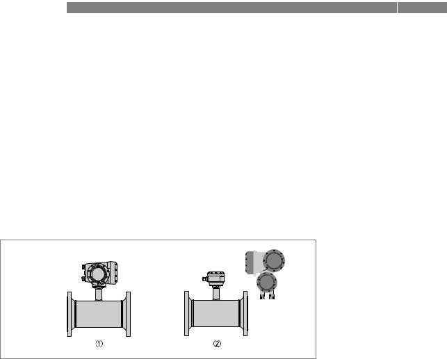
2.2 Device description
This ultrasonic flowmeter is designed for the continuous measurement of actual volume flow, mass flow, flow speed, velocity of sound, gain, SNR and diagnosis value.
Exclusively for measuring conductive and / or non-conductive fluids in closed, completely filled pipeline circuits.
Your measuring device is supplied ready for operation. The factory settings for the operating data have been made in accordance with your order specifications.
The following version is available:
•Compact version (the signal converter is mounted directly on the measuring sensor)
•Remote version (electrical connection to the measuring sensor via signal cable)
1Compact version
2Remote version
6 |
www.krohne.com |
11/2013 - QS OPTISONIC 3400_4002741202_R02-en |
|
|
INSTALLATION 2 |
|
OPTISONIC 3400 |
|
|
|
|
2.3 Nameplates
INFORMATION!
Look at the device nameplate to ensure that the device is delivered according to your order. Check for the correct supply voltage printed on the nameplate.
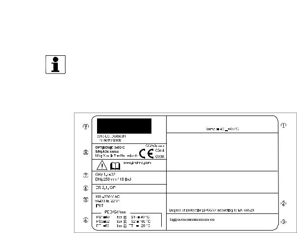
2.3.1 Example of nameplate for the compact version
Figure 2-2: Example of nameplate for the compact version
1Ambient temperature
2Protection class
3Tag number
4PED data, type I / II / II or SEP
5Mains supply data
6Electronic revision number
7Calibration data
8Type designation of the flowmeter and CE sign with number(s) of notified body / bodies
9Name and address of the manufacturer
11/2013 - QS OPTISONIC 3400_4002741202_R02-en |
www.krohne.com |
7 |

2 INSTALLATION |
OPTISONIC 3400 |
|
2.3.2 Nameplate for the measuring sensor (field version)
Examples for measuring sensor versions in Standard version.
1.Ambient temperature
2.Protection class
3.Tag number
4.PED data, type I / II / II or SEP
5.Calibration data
6.Type designation of the flowmeter and CE sign with number(s) of notified body / bodies
7.Name and address of the manufacturer
2.3.3Examples of nameplates on the signal converter (field version)
Figure 2-3: Examples of nameplates on the signal converter (field version)
1Ambient temperature
2Protection class
3Tag number
4PED data, type I / II / II or SEP
5Mains supply data
6Electronics revision numbers
7Calibration data
8Type designation of the flowmeter and CE sign with number(s) of notified body / bodies
9Name and address of the manufacturer
8 |
www.krohne.com |
11/2013 - QS OPTISONIC 3400_4002741202_R02-en |

|
|
INSTALLATION 2 |
|
OPTISONIC 3400 |
|
|
|
|
Electrical connection data of inputs/outputs (example of basic version)
1Power supply (AC: L and N, DC: L+ and L-, PE for ≥ 24V AC, FE for ≤ 24 VAC and DC)
2Connection data of connection terminal D/D-
3Connection data of connection terminal C/C-
4Connection data of connection terminal B/B-
5Connection data of connection terminal A/A-, A+ only operable in basic version
•A = active mode; the signal converter supplies the power for connection of the subsequent devices
•P = passive mode; external power supply required for operation of the subsequent devices
•N/C = connection terminals not connected
11/2013 - QS OPTISONIC 3400_4002741202_R02-en |
www.krohne.com |
9 |
2 INSTALLATION |
OPTISONIC 3400 |
|
2.4Storage
•Store the device in a dry, dust-free location.
•Avoid continuous direct sunlight.
•Store the device in its original packaging.
•Storage temperature: -50...+70°C / -58...+158°F
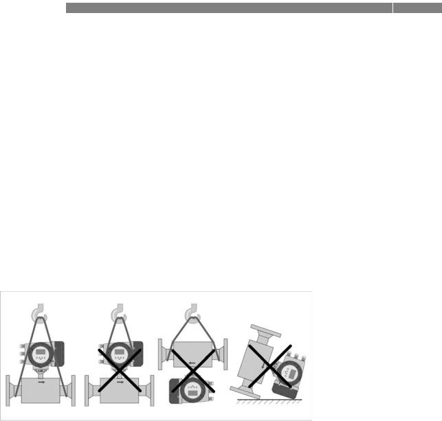
2.5Transport
Signal converter
• Do not lift the signal converter by the cable glands.
Measuring sensor
•Do not lift the measuring sensor by the connection box.
•Use hoisting belts only.
•To transport flange devices, use lifting straps. Wrap these around both process connections.
Figure 2-4: Transport
10 |
www.krohne.com |
11/2013 - QS OPTISONIC 3400_4002741202_R02-en |
|
|
INSTALLATION 2 |
|
OPTISONIC 3400 |
|
|
|
|
2.6 Pre-installation requirements
INFORMATION!
To assure a quick, safe and uncomplicated installation, we kindly request you to make provisions as stated below.
Make sure that you have all necessary tools available:
•Allen key (4 mm)
•Small screwdriver
•Wrench for cable glands
•Wrench for pipe mounting bracket (remote version only) see; on page 17
•Torque wrench for installing flowmeter in pipeline
2.7General requirements
INFORMATION!
The following precautions must be taken to ensure reliable installation.
•Make sure that there is adequate space to the sides.
•Protect the signal converter from direct sunlight and install a sun shade if necessary.
•Signal converters installed in control cabinets require adequate cooling, e.g. by fan or heat exchanger.
•Do not expose the signal converter to intense vibration. The flowmeters are tested for a vibration level in accordance with IEC 68-2-6.
2.7.1Vibration
Figure 2-5: Avoid vibrations
INFORMATION!
In case of expected vibrations, please install a field version.
11/2013 - QS OPTISONIC 3400_4002741202_R02-en |
www.krohne.com |
11 |
 Loading...