


|
© KROHNE 07/02 |
7.02253.21.00 |
|
|
|
|
|
|
|
|
|
|
|
|
|
|
|
||
|
|
|
|
|
|
|
|||
|
|
|
|
|
|
|
|
|
|
|
|
|
|
|
|
|
|
|
|
|
|
|
|
|
|
|
|
|
|
Addition to the
installation and operating instructions
ALTOFLUX IFM 4080 K-EEx / i-EEx
PROFIFLUX IFM 5080 K-EEx / i-EEx
VARIFLUX IFM 6080 K-EEx / i-EEx
Compact electromagnetic flowmeters
Variable area flowmeters
Vortex flowmeters
Flow controllers
Electromagnetic flowmeters
Ultrasonic flowmeters
Mass flowmeters
Level measuring instruments
Communications technology
Engineering systems & solutions
Switches, counters, displays and recorders
Heat metering
Pressure and temperature

WARNING ! |
No changes regarding safety may be made to the devices. Unauthorized |
|
changes might affect the explosion safety of the devices. |
Be sure to follow these instructions !
IMPORTANT ! ∙ The prescriptions and regulations as well as the electrical data described in the EC-type examination certificate must be obeyed.
∙Beside the instructions for electrical installations in non-hazardous locations according to the applicable national standard (e.g. IEC 364), especially the regulations in EN 60079-14 "Electrical installations in hazardous locations" or equivalent national standard must be followed.
∙Installation, establishment, utilization and maintenance are only allowed to be executed by personnel with an education in explosion safety!
These additional instructions are an extension to the Installation and Operating Instructions and only apply to the EEx version of the IFM x080 K - EEx or IFM x080 K / i -EEx electromagnetic compact flowmeter. All technical information described in the “Installation and Operating Instructions ” are applicable, when not specifically excluded, completed or replaced by the instructions in these additional instructions.

Content
1 |
System components |
3 |
1.1 |
General information ALTOFLUX IFM 4080 / … EEx |
4 |
1.2 |
General information PROFIOFLUX IFM 5080 / … EEx |
6 |
1.3 |
General information VARIFLUX IFM 6080 / … EEx |
8 |
1.4 |
IFC 090 / … -EEx signal converter |
10 |
1.4.1 |
Electronics compartment |
10 |
1.4.2 |
Terminal compartment |
10 |
1.5 |
Electronics unit |
11 |
2 |
Electrical connection |
11 |
2.1 |
Equipotential bonding system |
12 |
2.2 |
Connecting cables |
12 |
2.3 |
Connection diagram |
13 |
2.4 |
Regular IFC 090 - EEx electronics unit |
14 |
2.5 |
Modis version IFC 090 I |
15 |
2.6 |
Connection diagrams MODIS |
16 |
3 |
Operation of the signal converter |
22 |
4 |
Maintenance |
22 |
5 |
Service |
23 |
5.1 |
General information for replacements |
24 |
5.2 |
Replacement of electronics unit |
25 |
5.3 |
Replacement of power fuse(s) |
27 |
5.4 |
Changing power supply voltage |
30 |
6 |
Ordering information |
31 |
6.1 |
Regular IFC 090 - EEx electronics unit |
31 |
6.2 |
MODIS version IFC 090 - EEx electronics unit |
31 |
7 |
Declaration of conformity |
31 |
7.1 |
Declaration of conformity of ALTOFLUX IFM 4080 K … EEx |
32 |
7.2 |
Declaration of conformity of PROFIOFLUX IFM 5080 … EEx |
33 |
7.3 |
Declaration of conformity of VARIFLUX IFM 6080 … EEx |
34 |
8 |
EC-type examination Certificates |
34 |
8.1 |
ALTOFL UX IFM 4080 K … EEx Certificate |
35 |
8.2 |
PROFIOFLUX IFM 5080 … EEx Certificate |
38 |
8.3 |
VARIFLUX IFM 6080 … EEx Certificate |
40 |

1 System components
1.1General information ALTOFLUX IFM 4080 / … EEx
This meter complies with the European Directive 94/9/EC (ATEX 100a) and approved for hazardous classified locations of Zone 1 and 2 under EC-type Examination Certificate number:
KEMA 01 ATEX 2200 X
The compact flowmeter is available in two types, namely: IFM 4080 K-EEx regular explosion protected version;
IFM 4080 K/i-EEx, MODIS version. This type has intrinsically safe signal output circuits, which are provided by two on the IFC 090i-EEx electronics unit installed MODIS modules.
The regular IFM 4080 K-EEx compact flowmeter is designed for ambient temperatures (Ta) in the range of -20°C (special -40°C) up to +60°C, the MODIS version type IFM 4080 K/i-EEx is rated for ambient temperatures from -20°C up to +60°C.
The allowed process liquid temperature is limited by the maximum occuring surface temperature of system components in the combustible atmosphere that (possibly) surrounds the apparatus, determined by the temperature class of the atmosphere (first column of the tables). See table 1 and 2 below for details.
For dusts the second column of the two below listed tables is applicable.
Temperature classification DN200 and larger
Temperature class |
Max. surface |
Maximum process liquid temperature |
|||
temperature |
|
|
|
||
(for gases) |
Ta ≤ 40°C |
Ta ≤ 50°C |
Ta ≤ 60°C |
||
(for dusts) |
|||||
|
|
|
|
||
T6 |
T85°C |
75°C |
70°C |
70°C |
|
T5 |
T100°C |
95°C |
90°C |
75°C |
|
T4 |
T135°C |
130°C |
115°C |
75°C |
|
T3 |
T180°C |
150°C |
115°C |
75°C |
|
Temperature classification DN 25…150 with PFA liner |
|
|
|||
Temperature class |
Max. surface |
Maximum process liquid temperature |
|||
temperature |
|
|
|
||
(for gases) |
Ta ≤ 40°C |
Ta ≤ 50°C |
Ta ≤ 60°C |
||
(for dusts) |
|||||
|
|
|
|
||
T6 |
T85°C |
70°C |
70°C |
70°C |
|
T5 |
T100°C |
85°C |
85°C |
85°C |
|
T4 |
T135°C |
120°C |
120°C |
115°C |
|
T3 |
T180°C |
180°C |
180°C |
115°C |
|
Use heat-resistant cables above |
- |
- |
50°C |
||
The IFM 4080 K / … EEx flowmeter consists of the IFC 090/…-EEx signal converter unit, which is screwed on top of the prim ary head (i.e. measuring unit).
The compact flowmeter is marked with one of the codes below, depending on the meter size:
DN25-150 |
II 2GD EEx d [ib] IIC T6…T3 (EEx d terminal compartment) or |
|
II 2GD EEx de [ib] IIC T6…T3 (EEx e terminal compartment). |
DN200 and up |
II 2GD EEx de [ib] IIC T6…T3 (both EEx d and EEx e terminal compartment). |
In case of the MODIS version IFM 4080 K / i-EEx , the electronics unit of type IFC 090i-EEx is provided with protective modules, which provide intrinsically safe output signals of category "ia".
The flowmeter is then marked with one of the following codes:
|
DN25-150 |
II 2GD EEx d [ia] [ib] IIC T6…T3 (EEx d terminal compartment) or |
|
|
|
II 2GD EEx de [ia] [ib] IIC T6…T3 (EEx e terminal compartment) |
|
|
DN200 and up |
II 2GD EEx de [ia] [ib] IIC T6…T3 |
|
|
|
(both EEx d and EEx e terminal compartment) |
|
|
|
|
|

For details see the EC-type Examination Certificate in Sect. 8.1 of these instructions .
Primary head
The primary head contains two field coils (see table for type of protection) and two electrodes in type of protection intrinsic safety category "ib" according to EN 50020.
Types of protection of primary head
Meter size |
Type of protection |
||
DN25 up to DN150 |
Housing: |
Flameproof enclosure "d" according to EN 50018 |
|
|
|
||
|
Electrodes: |
Intrinsic safety "ib" according to EN 50020 |
|
DN200 and larger |
Field coils: |
Increased safety "e" according to EN 50019 |
|
Electrodes: |
Intrinsic safety "ib" according to EN 50020 |
||
|
|||
NOTE: The intrinsically safe electrode circuits of the IFM 4080K/…-EEx compact flowmeter are only internal circuits and not accessible for the customer
Data plates of ALTOFLUX IFM 4080 K IFM 4080 K … EEx
|
|
|
|
|
|
|
|
|
|
|
|
|
|
|
|
Kerkeplaat 12 |
|
|
|
|
|
|
|
|
|
|
|
|||
|
|
|
|
|
|
|
|
|
|
|
|
|
|
|
|
3313 LC Dordrecht |
|
|
|
|
|
|
|
|
|
|
|
|||
|
|
|
|
|
|
|
|
|
|
|
|
|
|
|
|
The Netherlands |
|
|
|
|
|
|
|
|
|
|
|
|||
|
|
|
|
|
|
Altometer |
|
|
|
|
|
|
|
|
|
0344 |
|
|
|
|
||||||||||
|
|
|
|
|
|
|
|
|
|
|
|
|
|
|
|
|
|
|
|
|
|
|
YEAR OF |
|
|
|||||
|
TYPE |
|
IFM 4080 K-EEx |
|
|
|
|
|
|
|
|
|
|
|
||||||||||||||||
|
|
|
|
|
|
|
|
|
|
|
PRODUCTION |
|
|
|||||||||||||||||
|
|
|
|
|
|
|
|
KEMA 01 ATEX 2200 X |
|
|
|
|
|
|
|
|
|
|
|
|
|
|
|
|||||||
|
|
|
|
|
|
|
|
|
|
|
|
|
|
|
2002 |
|
|
|
|
|
|
|||||||||
|
|
|
|
|
|
|
|
|
|
|
|
|
|
|
|
|
|
|
|
|
|
|
|
|
|
|
|
|
||
|
|
|
|
|
|
|
|
II 2GD EEx d |
|
|
|
|
|
[ib] IIC T6...T3 |
|
|
IP65/67 |
|
|
|||||||||||
|
|
|
|
|
|
|
|
|
|
|
|
|
|
|
|
|
||||||||||||||
|
AMBIENT TEMPERATURE: -40...+60%%DC. |
|
|
|
|
|
T85...180%%DC |
|
|
|||||||||||||||||||||
|
|
|
|
|
|
|
|
|
|
|
|
|
|
|||||||||||||||||
|
SEE CERTIFICATE FOR MAXIMUM TEMPERATURES. |
|
|
|
|
|
|
|
|
|
|
|
|
|
||||||||||||||||
|
|
|
|
|
|
|
|
|
|
|
|
|
|
|
|
|
|
|
|
|
|
|
|
|
|
|
|
|
|
|
|
SERIALNO. |
|
|
|
|
|
|
|
|
|
|
|
|
|
|
|
|
|
|
|
|
|
|
|||||||
|
POWER |
|
|
|
|
|
|
|
Vac |
+ |
|
% - |
|
% |
|
|
|
+30% |
|
|
|
|||||||||
|
|
|
|
|
|
|
|
|
|
|
|
|
|
|
|
|||||||||||||||
|
|
|
|
|
|
|
|
|
|
|
|
|
Vdc |
|
|
|||||||||||||||
|
|
|
|
|
|
|
|
|
|
|
|
|
|
|
|
|
|
|
|
|
|
|
|
-25% |
|
|
|
|||
|
|
|
|
|
|
|
|
48-63Hz |
10VA |
Um=253V |
|
|
|
|
8W |
|
|
|||||||||||||
|
|
|
|
|
|
|
|
|
|
|
|
|
|
|
|
|
|
|
|
|
|
|
|
|
|
|
|
|
|
|
|
|
|
|
|
|
|
|
|
|
|
|
|
|
|
|
|
|
|
|
|
|
|
|
|
|
|
|
|
|
|
|
INTRINSICALLY SAFE CIRCUITS: ELECTRODE CIRCUIT, |
|
|
|
|
|
|
|
|
|
|
|
||||||||||||||||||
|
|
|
|
|
|
|
|
|
|
|
|
|||||||||||||||||||
|
ONLY INTERNAL CONNECTIONS. |
|
|
|
|
|
|
|
|
|
|
|
|
|
|
|
|
|
|
|||||||||||
|
DO NOT OPEN ENCLOSURE WHEN ENERGIZED ! |
|
|
|
|
|
|
|
|
|
|
|
|
|
||||||||||||||||
|
WAITING TIME BEFORE OPENING OF THE FLAMEPROOF |
|
|
|
|
|
|
|
|
|
|
|
||||||||||||||||||
|
ENCLOSURE: T6 %%242 20 MIN.; |
T5 %%242 11 MIN. |
|
|
|
|
|
|
|
|
|
|
|
|||||||||||||||||
|
MAX. SHORT-CIRCUIT CURRENT OF MAINS: |
|
|
|
|
|
|
|
|
|
|
A |
|
|
||||||||||||||||
|
|
|
|
|
|
|
|
|
|
|
|
|
||||||||||||||||||
|
|
|
|
|
|
|
|
|
|
|
|
|
|
|
|
|
|
|
|
|
|
|
|
|
|
|
|
|
|
|
SPACE FOR ADDITIONAL DATA
IFM 4080 K / i … EEx
|
|
|
|
|
|
|
|
|
|
|
|
|
|
|
|
|
|
|
|
|
|
|
Kerkeplaat 12 |
|
|
|
|
|
|
|
|
|
|
|
|
|
|
|
|
|
|
|
|
|
|
|
|
|
|
|
|
|
|
|
|
|
|
|
3313 LC Dordrecht |
|
|
|
|
|
|
|
|
|
|
|
|
|
|
|
|
|
|
|
|
|
|
|
|
|
|
|
|
|
|
|
|
|
|
|
The Netherlands |
|
|
|
|
|
|
|
|
|
|
|
|
|
|
|
|
|
|
|
|
Altometer |
|
|
|
|
|
|
|
|
0344 |
|
|
|
|
|
|||||||||||||
|
|
|
|
|
|
|
|
|
|
|
|
|
|
|
|
|
|
|
|
|
|
|
|
|
|
|
|
YEAR OF |
|
|
|
||||
|
|
|
TYPE |
|
IFM 4080 K/i-EEx |
|
|
|
|
|
|
|
|||||||||||||||||||||||
|
|
|
|
|
|
|
|
|
PRODUCTION |
|
|
|
|||||||||||||||||||||||
|
|
|
|
|
|
|
|
|
|
KEMA 01 ATEX 2200 X |
|
|
|
|
|
|
|
|
|
|
|
|
|
|
|||||||||||
|
|
|
|
|
|
|
|
|
|
|
|
|
|
|
|
2002 |
|
|
|
|
|
|
|
||||||||||||
|
|
|
|
|
|
|
|
|
|
|
|
|
|
|
|
|
|
|
|
|
|
|
|
|
|
|
|
|
|
|
|
|
|||
|
|
|
|
|
|
|
|
|
|
II 2GD EEx d |
|
|
|
|
|
|
|
[ib] [ia] IIC T6...T3 |
|
|
|
IP65/67 |
|
|
|
||||||||||
|
|
|
|
|
|
|
|
|
|
|
|
|
|
|
|
|
|
|
|
|
|
|
|
|
|
|
|
|
|
|
|||||
|
|
|
|
|
|
|
|
|
|
|
|
|
|
|
|
|
|
|
|
|
|
|
|
|
|
|
|
|
|
|
|||||
|
|
|
AMBIENT TEMPERATURE: -20...+60%%DC. |
|
|
|
T85...180%%DC |
|
|
|
|||||||||||||||||||||||||
|
|
|
|
|
|
|
|
|
|
|
|
|
|
||||||||||||||||||||||
|
|
|
SEECERTIFICATEFORMAXIMUMTEMPERATURES. |
|
|
|
|
|
|
|
|
|
|
|
|||||||||||||||||||||
|
|
|
SERIAL NO. |
|
|
|
|
|
|
|
|
|
|
|
|
|
|
|
|
|
|
|
|
|
|
|
|
|
|
||||||
|
|
|
POWER |
|
|
|
|
|
|
Term. 24Vac,+10%/-15%,48-63Hz,10W |
|
|
|
|
|
|
|
|
|
|
|
||||||||||||||
|
|
|
|
|
|
|
|
|
|
|
|
|
|
|
|
|
|
|
|
||||||||||||||||
|
|
|
|
|
|
|
|
|
1L~ |
,0L |
~ |
|
|
24Vdc,+30%/-25%,10W,Um=253V |
|
|
|
||||||||||||||||||
|
|
|
|
|
|
|
|
|
|
|
|
|
|
|
|
|
|
|
|||||||||||||||||
|
|
|
|
|
|
|
|
|
|
|
|
|
|
Term. 100...230Vac,+10%/-15% |
|
|
|
|
|
|
|
|
|
|
|
||||||||||
|
|
|
|
|
|
|
|
|
|
|
|
|
|
|
|
|
|
|
|
|
|
|
|
|
|||||||||||
|
|
|
|
|
|
|
|
|
|
|
|
|
|
L, N |
|
|
|
|
|
48-63Hz,8W,Um=253V |
|
|
|
|
|
|
|
|
|
|
|
||||
|
|
|
|
|
|
|
|
|
|
|
|
|
|
|
|
|
|
|
|
|
|
|
|
|
|
|
|
|
|
||||||
|
|
|
|
|
|
|
|
|
|
|
|
|
|
|
|
|
|
|
|
|
|
|
|
|
|
|
|
|
|
|
|
|
|
|
|
|
|
|
|
|
|
|
|
|
|
|
|
|
|
|
|
|
|
|
|
|
|
|
|
|
|
|
|
|
|
|
|
|
|
|
|
|
|
|
DO NOT OPEN ENCLOSURE WHEN ENERGIZED ! |
|
|
|
|
|
|
|
|
|
|
|
|||||||||||||||||||||
|
|
|
WAITING TIME BEFORE OPENING OF THE FLAMEPROOF |
|
|
|
|
|
|
|
|
|
|
|
|||||||||||||||||||||
|
|
|
ENCLOSURE: T6 %%242 20 MIN.; |
T5 %%242 11 MIN. |
|
|
|
|
|
|
|
|
|
|
|
||||||||||||||||||||
|
|
|
MAX. SHORT-CIRCUIT CURRENT OF MAINS: |
|
|
|
|
|
|
|
A |
|
|
|
|||||||||||||||||||||
|
|
|
|
|
|
|
|
|
|
|
|
|
|
|
|
|
|
|
|
|
|
|
|
|
|
|
|
|
|
|
|
|
|
|
|
|
|
|
|
|
|
|
|
|
|
|
|
|
|
|
|
|
|
|
|
|
|
|
|
|
|
|
|
|
|
|
|
|
|
|
|
|
|
|
INTRINSICALLYSAFECIRCUITS |
|
|
|
|
|
|
|
|
|
|
|
|
|
|
|
|
|
|||||||||||||||
|
|
|
Electrode circuit: only internal connections |
|
|
|
EEx ib IIC |
|
|
|
|||||||||||||||||||||||||
|
|
|
|
|
|
|
|
|
%%uTerm. |
|
|
|
|
|
|
|
|
|
|
|
|
|
|
|
|
|
|
|
|||||||
|
|
|
|
|
|
|
|
T |
|
|
|
|
|
|
|
Passive output |
|
|
|
|
|
|
|
|
|
|
|
||||||||
|
|
|
|
|
|
|
|
|
|
|
|
|
|
|
|
|
|
|
|
|
|
|
|
|
|
||||||||||
|
|
|
|
|
|
|
|
I /I |
|
|
|
|
|
|
|
|
|
|
|
|
|
|
|
|
|
|
|||||||||
|
|
|
|
|
|
|
|
B1/B1 |
T |
|
Ui=30V; Ii=250mA; Pi=1.0W |
|
|
|
|
|
|
|
|
|
|
|
|||||||||||||
|
|
|
|
|
|
|
|
B2/B2 |
|
T |
|
Ci=5nF; Li=0; |
EEx ia IIC |
|
|
|
|||||||||||||||||||
|
|
|
|
|
|
|
|
|
|
|
|
|
|
|
|
|
|
|
|
|
|
|
|
|
|
|
|
|
|
|
|
|
|
|
|
|
|
|
|
|
|
|
|
D/D |
|
T |
|
|
|
|
|
Passive output |
|
|
|
|
|
|
|
|
|
|
|
||||||||
|
|
|
|
|
|
|
|
|
|
|
|
|
|
|
|
|
|
|
|
|
|
|
|
|
|||||||||||
|
|
|
|
|
|
|
|
|
|
|
|
|
|
|
|
|
|
|
|
|
|
|
|
|
|
||||||||||
|
|
|
|
|
|
|
|
|
|
|
|
|
|
|
|
|
Ui=30V; Ii=300mA; Pi=4.2W |
|
|
|
|
|
|
|
|
|
|
|
|||||||
|
|
|
|
|
|
|
|
|
|
|
|
|
|
|
|
|
Ci=5nF; Li=0; |
EEx ia IIC |
|
|
|
||||||||||||||
|
|
|
|
|
|
|
|
|
|
|
|
|
|
|
|
|
|
|
|
|
|
|
|
|
|
|
|
|
|
|
|
|
|
|
|
|
|
|
|
|
|
|
|
I+/I |
|
|
|
|
|
|
|
Active output |
|
|
|
|
|
|
|
|
|
|
|
||||||||
|
|
|
|
|
|
|
|
|
|
|
|
|
|
|
|
|
|
|
|
|
|
|
|
|
|
||||||||||
|
|
|
|
|
|
|
|
B1+/B1 |
|
|
|
|
|
Uo=23.5V; Io=98mA; Po=0.6W |
|
|
|
|
|
|
|
|
|
|
|
||||||||||
|
|
|
|
|
|
|
|
|
|
|
|
|
|
|
|
|
Co=132nF; Lo=4mH; |
EEx ia IIC |
|
|
|
|
|
|
|||||||||||
|
|
|
|
|
|
|
|
|
|
|
|
|
|
|
|
|
|
|
|
|
|
|
|
|
|
|
|
|
|
|
|
|
|
|
|

1.2PROFIFLUX IFM 5080 K … EEx
The Profiflux IFM 5080 K/…-EEx magnetic-inductive compact flowmeter is in accordance with the European Directive 94/9/EC (ATEX 100a) and approved for hazardous classified locations of Zone 1 and 2 under EC-type Examination Certificate number:
KEMA 01 ATEX 2262 X
The compact flowmeter is available in two types, namely:
•IFM 5080 K-EEx regular explosion protected version;
•IFM 5080 K/i-EEx, MODIS version. This type has intrinsical safe signal output circuits, which are provided by two on the IFC 090i-EEx electronics unit installed MODIS modules (see Sect. 1.5 for details.
The regular IFM 5080 K-EEx compact flowmeter as well as the so-called MODIS version type IFM 5080 K/i-EEx is designed for ambient temperatures (Ta) of -20°C up to +60°C. The allowed process liquid temperature is limited by the maximum occuring surface temperature of system components in the combustible atmosphere that (possibly) surrounds the apparatus, determined by the temperature class of the atmosphere, see table 1 below.
Temperature classification
Temperature |
Max. surface |
Maximum process liquid temperature |
|
||
Class |
Temperature |
Ta ≤ 40°C |
Ta ≤ 50°C |
Ta ≤ 60 °C |
|
|
|
|
|
|
|
T6 |
T80°C |
60°C |
55°C |
not allowed |
|
T5 |
T95°C |
75°C |
75°C |
70°C |
|
T4 |
T130°C |
115°C |
115°C |
75°C |
|
T3 |
T165°C |
155°C |
135°C |
75°C |
|
The IFM 5080 K/…-EEx compact flowmeter consists of the IFC 090/…-EEx signal converter unit, which is screwed on top of the IFS 5000-EEx primary head (i.e. measuring unit). The compact flowmeter is marked with the following code below:
II 2 GD EEx dme [ib] IIC T6…T3
In case of the MODIS version IFM 5080 K/i-EEx, the electronics unit of type IFC 090i-EEx is provided with protective modules, which provide intrinsical safe output signals of category "ia". The flowmeter is then marked with the code
II 2 GD EEx dme [ib] [ia] IIC T6…T3
For details see the EC-type Examination Certificate in Sect. 8.2 at the end of these additional instructions.

Primary head
The IFS 5000-EEx primary head of the IFM 5080 K/…-EEx compact flowmeter contains two field coils above and below the measuring tube and two electrodes inside the ceramics measuring tube on both sides. The field coils have type of protection increased safety "e" according to EN 50019 and encapsulation "m" according to EN 50028. The electrodes are provided with type of protection intrinsic safety "ib" according to EN 50020.
The primary head is available in meter sizes DN2.5 up to DN100. The IFC 090/…-EEx signal converter (described in Sect. 1.4-1.5) is mounted on top of the primary head by four recessed head screws of size M6 with internal hexagonal socket set.
Note: The intrinsically safe electrode circuits of the IFM 5080K/…-EEx compact flowmeter are only internal circuits and not accessible for the customer.
Data plates of ALTOFLUX IFM 5080 K
IFM 5080 K … EEx
Kerkeplaat 12
3313 LC Dordrecht
The Netherlands
Altometer
TYPE IFM 5080 K-EEx
KEMA 01 ATEX 2262 X
II 2GD EEx dme [ib] IIC T6...T3
AMBIENT TEMPERATURE: -20...+60%%DC.
SEE CERTIFICATE FOR MAXIMUM TEMPERATURES. SERIAL NO.

 0344
0344
YEAR OF
PRODUCTION
2002
IP65/67
T80...165%%DC
|
POWER |
|
|
Vac |
+ |
|
|
% - |
|
% |
|
|
Vdc |
+30% |
|
|
|
|
|
|
|
|
|
|
-25% |
|
|||||||
|
|
48-63Hz |
10VA |
Um=253V |
|
|
|
8 W |
|
|
|
|||||
|
|
|
|
|
|
|
|
|
|
|
|
|
|
|
|
|
|
INTRINSICALLY SAFE CIRCUITS: ELECTRODE CIRCUIT, |
|
|
|
|
|
|
|
||||||||
|
ONLY INTERNAL CONNECTIONS. |
|
|
|
|
|
|
|
|
|
|
|
|
|
||
|
DO NOT OPEN ENCLOSURE WHEN ENERGIZED ! |
|
|
|
|
|
|
|
|
|
|
|||||
|
WAITING TIME BEFORE OPENING OF THE FLAMEPROOF |
|
|
|
|
|
|
|
||||||||
|
ENCLOSURE: T6 %%242 20 MIN.; |
T5 %%242 11 MIN. |
|
|
|
|
|
|
|
|||||||
|
MAX. SHORT-CIRCUIT CURRENT OF MAINS: |
A |
|
|
|
|
|
|
|
|||||||
|
|
|
|
|
|
|
|
|
|
|
|
|
|
|
|
|
|
|
|
|
|
|
|
|
|
|
|
|
|
|
|
|
|
SPACE FOR ADDITIONAL DATA
IFM 5080 K / i … EEx
Kerkeplaat 12
3313 LC Dordrecht
The Netherlands
Altometer
TYPE IFM 5080 K/i-EEx
KEMA 01 ATEX 2262 X
II 2GD EEx dme [ib] [ia] IIC T6...T3
AMBIENT TEMPERATURE: -20...+60%%DC.
SEE CERTIFICATE FOR MAXIMUM TEMPERATURES. SERIAL NO.
POWER

 0344
0344
YEAR OF
PRODUCTION
2002
IP65/67
T80..165%%DC
|
DO NOT OPEN ENCLOSURE WHEN ENERGIZED ! |
|
|
|
|
|
|
|
|
|||||||
|
WAITING TIME BEFORE OPENING OF THE FLAMEPROOF |
|
|
|
|
|
|
|
|
|||||||
|
ENCLOSURE: |
|
T6 %%242 20 MIN.; T5 %%242 11 MIN. |
|
|
|
|
|
|
|
|
|||||
|
MAX. SHORT-CIRCUIT CURRENT OF MAINS: |
A |
|
|
|
|
|
|
|
|
||||||
|
|
|
|
|
|
|
|
|
|
|
|
|
|
|
|
|
|
|
|
|
|
|
|
|
|
|
|
|
|
|
|
|
|
|
INTRINSICALLY SAFE CIRCUITS |
|
|
|
|
|
|
|
|
|
||||||
|
Electrode circuit: only internal connections |
|
|
EEx ib IIC |
|
|
|
|||||||||
|
|
|
|
%%uTerm. |
|
|
|
|
|
|
|
|
|
|
||
|
|
|
|
T |
|
|
Passive output |
|
|
|
|
|
|
|
|
|
|
|
|
|
|
|
|
|
|
|
|
|
|
|
|
||
|
|
|
|
I /I |
|
|
|
|
|
|
|
|
|
|
|
|
|
|
|
|
B1/B1 |
|
T |
Ui=30V; Ii=250mA; Pi=1.0W |
|
|
|
|
|
|
|
|
|
|
|
|
|
B2/B2 |
|
T |
Ci=5nF; Li=0; |
EEx ia IIC |
|
|
|
|
|
|
|
|
|
|
|
|
|
|
|
|
|
|
|
|
|
|
|
|
|
|
|
|
|
D/D |
T |
|
Passive output |
|
|
|
|
|
|
|
|
|
|
|
|
|
|
|
|
|
|
|
|
|
|
|
|||
|
|
|
|
|
|
|
|
|
|
|
|
|
|
|
||
|
|
|
|
|
|
|
Ui=30V; Ii=300mA; Pi=4.2W |
|
|
|
|
|
|
|
|
|
|
|
|
|
|
|
|
Ci=5nF; Li=0; |
EEx ia IIC |
|
|
|
|
|
|
|
|
|
|
|
|
|
|
|
|
|
|
|
|
|
|
|
|
|
|
|
|
|
I+/I |
|
|
Active output |
|
|
|
|
|
|
|
|
|
|
|
|
|
|
|
|
|
|
|
|
|
|
|
|
||
|
|
|
|
B1+/B1 |
|
Uo=23.5V; Io=98mA; Po=0.6W |
|
|
|
|
|
|
|
|
||
|
|
|
|
|
|
|
Co=127nF; Lo=4mH; |
EEx ia IIC |
|
|
|
|
|
|||
|
|
|
|
|
|
|
|
|
|
|
|
|
|
|
|
|

1.3VARIFLUX IFM 6080 K … EEx
The Variflux IFM 6080 K/…-EEx magnetic-inductive compact flowmeter is in accordance with the European Directive 94/9/EC (ATEX 100a) and approved for hazardous classified locations of Zone 1 and 2 under EC-type Examination Certificate number:
KEMA 02 ATEX 2021 X
The compact flowmeter is available in two types, namely:
•IFM 6080 K-EEx regular explosion protected version
•IFM 6080 K/i-EEx, MODIS version. This type has intrinsical safe signal output circuits, which are provided by two on the IFC 090i-EEx electronics unit installed MODIS modules.
The regular IFM 6080 K-EEx compact flowmeter is designed for ambient temperatures (Ta) in the range of -40°C up to +60°C, the so-called MODIS version IFM 6080 K/i-EEx is rated for ambient temperatures from -20°C up to +60°C. The allowed process liquid temperature is limited by the occuring surface temperature of system components in the combustible atmosphere that (possibly) surrounds the apparatus, determined by the temperature class of the atmosphere, see table.
Temperature classification
Temperature |
Maximum surface |
Maximum process liquid temperature |
|
class |
Temperature |
Ta ≤ 50°C |
Ta ≤ 60°C |
T6 |
T80°C |
70°C |
70°C |
T5 |
T95°C |
85°C |
85°C |
T4 |
T130°C |
120°C |
100°C |
T3 |
T190°C |
180°C |
100°C |
The regular IFM 6080 K-EEx compact flowmeter consists of the IFC 090-EEx signal converter, which is screwed on top of the IFS 6000-EEx primary head (i.e. measuring unit). The compact flowmeter is marked with the following code below, depending on the meter size:
•DN2.5-15: II 2GD EEx dme [ib] IIC T6…T3
•DN25-80: II 2GD EEx d [ib] IIC T6…T3 ("EEx d" terminal compartment) or
II2GD EEx de [ib] IIC T6…T3 ("EEx e" terminal compartment)
•DN2.5-15: II 2GD EEx dme [ib] [ia] IIC T6…T3
•DN25-80: II 2GD EEx d [ib] [ia] IIC T6…T3 ("EEx d" terminal compartment) or
II2GD EEx de [ib] [ia] IIC T6…T3 ("EEx e" terminal compartment)
All meters are also marked with the maximum surface temperature T80…T190°C because of the dust classification. See for details the EC-type examination certificate in Sect. 8.3 of these additional instructions.
Primary head
The IFS 6000-EEx primary head of the IFM 6080 K/…-EEx compact flowmeter contains two field coils and two electrodes in type of protection intrinsic safety category "ib" according to EN 50020. The type of protection of the field coils depends on meter size.

Types of protection of primary head
Meter size |
Type of protection |
|
DN2.5 up to DN15 |
Field coils: |
Increased safety "e" according to EN 50019 |
Encapsulation "m" according to EN 50028 |
||
|
Electrodes: |
Intrinsic safety "ib" according to EN 50020 |
DN25 up to DN80 |
Housing: |
Flameproof enclosure "d" according to EN |
50018 |
|
|
|
Electrodes: |
Intrinsic safety "ib" according to EN 50020 |
The IFC 090/…-EEx signal converter (described in Sect. 1.4-1.5) is mounted on top of the primary head by four recessed head screws of size M6 with internal hexagonal socket set.
Note
The intrinsically safe electrode circuits of the IFM 6080K/…-EEx compact flowmeter are only internal circuits and not accessible for the customer.
The two field coils inside the primary head are connected in series and provided with the type of protection increased safety "e" and encapsulation "m" (DN2.5-15). Meter size DN25-80 has a flameproof primary housing.
Data plates of ALTOFLUX IFM 6080 K
IFM 6080 K … EEx |
|
|
|
|
IFM 6080 K / i … EEx |
|
|||||||||
|
|
|
Kerkeplaat 12 |
|
|
|
|
|
|
|
|
|
Kerkeplaat 12 |
||
|
|
|
3313 LC Dordrecht |
|
|
|
|
|
|
|
|
|
3313 LC Dordrecht |
||
|
|
|
The Netherlands |
|
|
|
|
|
|
|
|
|
The Netherlands |
||
|
Altometer |
|
|
|
|
0344 |
|
Altometer |
|
|
0344 |
||||
TYPE |
IFM 6080 K-EEx |
|
|
|
|
YEAR OF |
|
TYPE |
IFM 6080 K/i-EEx |
|
YEAR OF |
||||
|
|
|
|
PRODUCTION |
|
PRODUCTION |
|||||||||
|
|
|
|
|
|
|
|
|
|
|
|
|
|||
|
KEMA 02 ATEX 2021 X |
|
|
|
2002 |
|
|
|
KEMA 02 ATEX 2021 X |
|
2002 |
||||
|
II 2GD EEx d |
|
|
[ib] IIC T6...T3 |
|
IP65/67 |
|
|
|
II 2GD EEx d |
|
|
[ib] [ia] IIC T6...T3 |
||
|
|
|
|
|
|
T80...190%%DC |
|
|
|
|
|
|
|
IP65/67 |
|
AMBIENT TEMPERATURE: -40...+60%%DC. |
|
|
|
|
AMBIENT TEMPERATURE: -20...+60%%DC. |
T80...190%%DC |
|||||||||
SEE CERTIFICATE FOR MAXIMUM TEMPERATURES. |
|
|
|
|
SEE CERTIFICATE FOR MAXIMUM TEMPERATURES. |
|
|||||||||
|
|
|
|
|
|
|
|
|
|
|
|
||||
SERIAL NO. |
|
|
|
|
|
|
SERIAL NO. |
|
|
|
|
|
|
||
|
|
|
|
|
|
|
|
|
|
|
|
|
|
||
POWER |
|
Vac |
+ |
% - |
% |
Vdc |
+30% |
POWER |
|
|
|
Term. 24Vac,+10%/-15%,48-63Hz,10W |
|||
|
|
|
|
1L~,0L |
~ |
24Vdc,+30%/-25%,10W,Um=253V |
|||||||||
|
-25% |
|
|
|
|
||||||||||
|
|
|
|
|
|
|
|
|
|
|
|||||
|
48-63Hz |
10VA |
Um=253V |
|
8W |
|
|
|
|
|
Term. 100...230Vac,+10%/-15% |
||||
|
|
|
|
|
|
|
|
|
|
|
|
||||
INTRINSICALLY SAFE CIRCUITS: ELECTRODE CIRCUIT, |
|
|
|
|
|
|
|
L, N |
|
48-63Hz,8W,Um=253V |
|||||
|
|
|
|
|
|
|
|
|
|
|
|||||
ONLYINTERNALCONNECTIONS. |
|
|
|
|
|
|
DO NOT OPEN ENCLOSURE WHILE ENERGIZED ! |
|
|||||||
|
|
|
|
|
|
|
|
|
|||||||
DO NOT OPEN ENCLOSURE WHILE ENERGIZED ! |
|
|
|
|
WAITING TIME BEFORE OPENING OF THE FLAMEPROOF |
||||||||||
WAITING TIME BEFORE OPENING OF THE FLAMEPROOF |
|
|
|
ENCLOSURE: |
T6 %%242 20 MIN.; |
T5 %%242 11 MIN. |
|||||||||
|
|
|
|
|
|
|
|
||||||||
ENCLOSURE: T6 %%242 20 MIN.; |
T5 %%242 11 MIN. |
|
|
|
MAX. SHORT-CIRCUIT CURRENT OF MAINS: |
A |
|||||||||
|
|
|
|
|
|
|
|
||||||||
MAX. SHORT-CIRCUIT CURRENT OF MAINS: |
|
|
|
|
A |
|
|
|
|
|
|
|
|||
|
|
|
|
|
|
|
|
INTRINSICALLY SAFE CIRCUITS |
|
|
|
||||
|
|
|
|
|
|
|
|
Electrode circuit: only internal connections |
EEx ib IIC |
||||||
|
|
|
|
|
|
|
|
|
%%uTerm. |
|
|
|
|||
|
|
|
|
|
|
|
|
|
T |
|
|
Passive output |
|
||
|
|
|
|
|
|
|
|
|
I /I |
|
|
|
|||
|
|
|
|
|
|
|
|
|
B1/B1 |
|
T |
Ui=30V; Ii=250mA; Pi=1.0W |
|||
|
|
|
|
|
|
|
|
|
|
|
|||||
|
|
|
|
|
|
|
|
|
B2/B2 |
|
T |
Ci=5nF; Li=0; |
EEx ia IIC |
||
|
|
|
|
|
|
|
|
|
|
|
|||||
|
SPACE FOR ADDITIONAL DATA |
|
|
|
|
D/D |
T |
|
Passive output |
|
|||||
|
|
|
|
|
|
|
|
|
|
|
|
||||
|
|
|
|
|
|
|
|
|
|
|
|
Ui=30V; Ii=300mA; Pi=4.2W |
|||
|
|
|
|
|
|
|
|
|
|
|
|
Ci=5nF; Li=0; |
EEx ia IIC |
||
|
|
|
|
|
|
|
|
|
I+/I |
|
|
Active output |
|
||
|
|
|
|
|
|
|
|
|
B1+/B1 |
|
Uo=23.5V; Io=98mA; Po=0.6W |
||||
|
|
|
|
|
|
|
|
|
|
|
|
Co=132nF; Lo=4mH; |
EEx ia IIC |
||

1.4IFC 090/…-EEx signal converter
The IFC 090/…-EEx signal converter consists of a cylindrical housing of die-casted aluminum, which has two separate compartments, divided from each other by an integrated wall with casted flameproof terminal feed-through. The neck at the bottom of the housing contains a flameproof cable feed-through. The signal converter housing is on both ends closed by a cylindrical threaded cover with O-ring sealing. The housing has an ingress protection degree of at least IP67 conform to EN 60529.
1.4.1 Electronics compartment
The electronics compartment accommodates the pre-certified IFC 090…-EEx electronics unit with approval number PTB 98 ATEX 2012 U. The electronics compartment is designed with type of protection flameproof enclosure "d" according to EN 50018. It is closed by a threaded flameproof display cover with glass window.
1.4.2 Terminal compartment
The terminal compartment has seven terminals for connection of the power supply and signal output circuits. Sect. 2 (Connection diagram)shows the terminal arrangement for the regular and MODIS version of the IFC 090/…-EEx signal converter. The terminal arrangement of the MODIS version (i.e. IFC 090i-EEx) is shown in Sect. 2 (Modis Converter). Two of the terminals are used for connection of the non-intrinsically safe power supply and four terminals (marked with "*") for the intrinsically safe, category "ia" signal outputs of the MODIS modules. The non-intrinsically and intrinsically safe terminals are separated from each other by a metal dividing plate, which is screwed to the remaining (not connected) M4 terminal. The two non-intrinsically safe power supply terminals are covered by an insulating plate.
The terminal compartment (with standard type of protection increased safety "e") is standard equipped with two ATEX approved "EEx e" cable glands. The terminal compartment can also be provided as a flameproof enclosure "d", in which case ATEX approved "EEx d" cable glands of size Pg13.5, Pg16 or M20x1.5 are either factory installed or must be installed by the customer. For flameproof conduit systems, the terminal compartment must have type of protection flameproof enclosure "d" according to EN 50018. The conduits must be sealed by "EEx d" approved (within the ATEX 100a directive) sealing devices (i.e. stopping box) directly at the conduit entrances of the as flameproof enclosure performed terminal compartment.
1.5Electronics unit
This electromagnetic compact flowmeter can be equipped with the regular IFC 090-EEx or with the IFC 090i-EEx electronics unit with intrinsically safe signal outputs (i.e. MODIS version). This version is descripted in the following.
Regular IFC090-EEx electronics unit
The IFC 090-EEx is used in the regular IFM 4080 K-EEx and can be equipped with one of the following power supplies (depends on the area of application).
Electrical data for power supply
Power supply |
Terminal |
Function |
Electrical data |
|
|
L |
Live |
Un = 100/115/200/230 Vac -15/+10% |
|
AC-versions |
N |
Neutral |
||
Pn = approx. 10 VA, Um = 253 V |
||||
|
PE |
Protective Ground |
||
|
|
|||
|
1L½ |
Live |
Un = 24 V ac/dc |
|
|
AC: -15/+10%, Pn=10 VA |
|||
AC/DC-version |
0L½ |
Neutral |
||
DC: -25/+30%, Pn=8 W |
||||
|
FE |
Functional Ground |
||
|
Um = 253 V |
|||
|
|
|
The IFC 090-EEx electronics unit is equipped with the following in-/output circuits. Terminals B1, B and B2 can be configured as status or pulse outputs or as control inputs via the software. See the table below for the electrical data of these in-/output circuits.
Electrical data of in-/output circuits
Terminals |
Description |
Nominal voltage |
Maximum current |
I+, I |
Current output |
15 V |
22 mA |
B1, B , B2 |
Pulse, status, control in-/outputs |
32 V |
150 mA |
IFC 090i-EEx unit with MODIS modules
The IFC 090i-EEx electronics unit is equipped with a pair of MODIS-modules. It is equipped with one of the following power supplies.
Electrical data of IFC 090i-EEx electronics unit
Power supply |
Terminals |
Function |
Electrical data |
|||
|
|
L |
Live |
Un = 100…230 Vac –15%/+10% |
||
AC-version |
N |
Neutral |
||||
Pn = 15 VA, Um = 253 V |
||||||
|
|
PE |
Protective Ground |
|||
|
|
|
|
|||
|
|
1L½ |
Live |
Un = 24 Vac/dc |
||
|
|
AC: |
-15%/+10% or 20.4…26.4 Vac |
|||
AC/DC-version |
0L½ |
Neutral |
||||
DC: |
-25%/+30% or 18…32 Vdc |
|||||
|
|
FE |
Functional Ground |
|||
|
|
Pn = 10 W, Um = 253 V |
||||
|
|
|
|
|||
NOTE: |
The mains fuses for both electronics units are listed in Sect. 6 of this manual. |
|||||

2 Electrical connection
2.1Equipotential bonding system
All EEx and EEx/i flowmeters must always be incorporated into the equipotential bonding system of the hazardous area. This connection can be achieved through the PE/FE conductor connected to the PE terminal in the terminal compartment (see figure of terminal arrangement below) or through a separate PE conductor, cross s ectional area at least 4 mm2, connected to the external PE clamp, placed below the converter housing.
2.2Connecting cables
NOTE: The below described cables are shown in the following connection diagram .
Cable A:
Signal cable for current output and binary outputs (pulse and status output): The cable parameters must be in accordance with the regulations in the EN 60079-14 "Electrical installations in hazardous locations" or an equivalent national standard. For the MODIS version with IFC 090iEEx electronics unit (right detail in connection diagram) the signal cable for the intrinsically safe signal in-/outputs must also conform the requirements as specified in the relevant standard national code of practice for the installation of electrical apparatus with type of protection Intrinsic Safety "i".
Cable B:
Power supply cable: The cable parameters must be in accordance with the regulations of the EN 60079-14 "Electrical installations in hazardous locations" or an equivalent national standard.
Rated voltage |
³ 500 V |
Examples: |
H07...-., H05...-. |
|
|
Equipotential bonding conductor |
4 mm2 (equivalent to AWG 10) |
Cross-sectional area: |

2.3Connection diagram
|
|
|
|
|
|
|
|
INTRINSICALLY SAFE |
|
|
|
|
|||
|
|
|
|
|
L |
N |
PE 100-230 Vac |
SIGNAL IN-/OUTPUTS |
L |
N |
PE |
100-230 Vac |
|||
|
|
|
|
|
|
(i.e. MODIS) |
|
L½ |
L½ |
FE |
24 Vac/dc |
||||
|
|
SIGNAL IN-/OUTPUTS |
|
L½ |
L½ |
FE 24 Vac/dc |
|
|
|||||||
|
|
|
|
|
|
|
|
|
|
|
|||||
|
|
A |
|
|
|
|
B |
A |
|
|
|
|
|
B |
|
|
|
|
|
|
|
|
|
|
|
|
|
|
|
||
|
|
IFC 090-EEx |
|
|
|
|
|
|
|
|
|
|
|||
|
|
Signal Converter |
|
|
|
|
|
|
|
|
|
|
|||
|
|
B1 B B2 I+ |
I |
L |
N |
PE |
x |
x |
x |
x |
1L½0L½ |
|
PE |
||
|
|
|
FE |
||||||||||||
|
|
FE |
|
|
|
|
|
|
|
||||||
|
|
|
|
|
|
|
|
|
|
||||||
|
|
BINARY |
CURRENT |
MAINS |
|
|
|
|
|
|
Unused terminal |
||||
|
|
OUTPUTS |
OUTPUT |
SUPPLY |
|
|
|
|
|
|
|||||
|
|
TERMINAL COMPARTMENT |
|
|
|
|
|
|
|
|
|
||||
|
|
Standard "EEx e" (Optional "EEx d") |
|
|
|
|
|
|
Separation plate |
||||||
|
|
ELECTRONICS COMPARTMENT (always "EEx d") |
IFC 090i-EEx |
|
|
|
|
||||||||
|
|
Signal Converter |
|
|
|
|
|||||||||
|
|
|
|
|
|
|
|
|
|
|
|
||||
|
|
electrode circuits |
field coil circuits |
|
|
|
|
OPTION: MODIS |
|||||||
|
|
|
|
|
|
|
Flameproof (EEx d) |
|
|
|
|
|
|
||
|
|
|
|
|
|
|
terminal feed-through |
|
|
|
|
|
|
||
|
|
|
|
|
|
|
Flameproof (EEx d) cable |
|
|
|
|
|
|
|
|
(OPTIONAL) |
|
|
|
|
|
|
feed-through |
|
|
|
|
|
|
|
|
|
|
|
|
|
|
|
Hazardous locations |
|
|
||||||
|
|
|
|
|
|
|
of Zone 1 and 2 |
|
|
||||||
2 |
|
|
|
|
|
|
|
|
|
||||||
³ 4 mm |
|
|
|
|
|
|
Field coil wires |
|
|
|
|
|
|
|
|
BONDING CONDUCTOR |
|
|
|
|
|
|
|
|
|
|
|
|
|
|
|
|
|
|
|
Coil |
|
|
|
|
|
|
|
|
|
||
|
|
|
|
|
|
|
|
|
|
|
|
|
|
|
|
EQUIPOTENTIAL |
Electrode cables |
E |
Flow tube |
E |
|
|
|
|
|
|
|
|
|
||
|
|
|
|
|
|
|
|
|
|
|
|
||||
Coil |
|
|
|
|
|
|
|
|
|
|
|
|
|
||
|
|
|
|
|
|
|
|
|
|
|
|
|
|
|
|
|
|
IFS 4000…-EEx |
|
|
|
|
|
|
|
|
|
|
|||
|
|
Primary Head |
|
|
|
|
|
|
|
|
|
|
|||
|
|
Intrinsically safe electrode circuits |
|
|
|
|
|
|
|
|
|||||
|
|
Increased safe field coil circuit |
|
|
|
|
|
|
|
|
|
||||
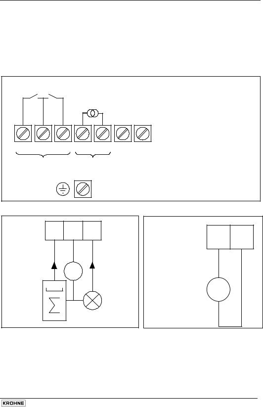
2.4Regular IFC 090-EEx electronics unit
The field cables that enter the terminal compartment of the IFC 090-EEx signal converter unit (i.e. power supply, current and binary outputs) are non-intrinsically safe. To connect external devices to the signal output terminals, the wiring requirements for the type of protection of the
compartment (standard: increased safety "e", optional:IFS x000flameproof… - EEx "d") must be conform to the international or national standard involved (e.g. ENPrimary60079-head14).
The terminal arrangement is shown by figure 1 below.
Terminal arrangement in terminal compartment
PULSE, STATUS OUTPUTS
RESP. CONTROL INPUTS
B1 |
B |
B2 |
BINARY
OUTPUTS
I+ |
I |
L |
N |
(100…240Vac / 48…63 Hz) |
CURRENT |
L½ |
L½ |
(24Vac/dc) |
|
|
|
|
||
OUTPUT |
|
|
|
|
PE (Protective Earth) terminal
FE (Functional Earth) terminal
Passive pulse/status output |
Active current output |
B1 B B2
I+ I
I ≤ 150 mA |
Uext |
I ≤ 150 mA |
|
½ |
+ |
||
Electronic or 000 |
|
|
Ri ≤ 500Ω mA |
electro- |
|
e.g. signal |
|
mechanical |
|
indicator |
_ |
totalizer |
|
|
|
Uext ≤ 32Vdc/24 Vac
Note: The binary outputs (terminals B1, B and B2) can only be configured as passive outputs, the current output (terminals I+ and I) can only be configured as active output.
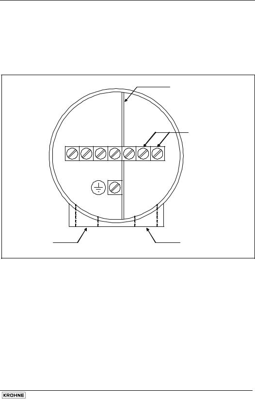
2.5MODIS version IFC 090i-EEx electronics unit
The field cables of the non-intrinsically safe power supply and the intrinsically safe, category "ia" signal outputs enter the terminal compartment of the IFC 090i-EEx signal converter unit via two separate entrances. To connect external devices to the intrinsically safe signal output terminals, the wiring requirements for their type of protection as well as of the compartment (standard: increased safety "e", optional: flameproof enclosure "d") must be conform to the international or national standard involved (e.g. EN 60079-14).
Terminal arrangement in terminal compartment
NC = not connected
Cable entrance for intrinsically safe signal cable
|
|
|
|
|
|
|
Metal dividing |
|
|
|
|
|
|
|
plate IS / non-IS |
|
|
|
|
|
|
|
terminals |
Connecting terminals |
|
|
|
Connecting |
|||
|
|
|
terminals for |
||||
for intrinsically safe |
|
|
|
non-intrinsically |
|||
signal in-/outputs |
|
|
|
safe power supply |
|||
* |
* |
* |
* |
NC |
1L½ 0L½ |
24 Vac/dc |
|
|
L |
N |
100…240 Vac |
||||
|
|
|
|
PE |
|
|
Protective Earth terminal |
|
|
|
|
|
|
|
Cable entrance for |
|
|
|
|
|
|
|
non-intrinsically |
|
|
|
|
|
|
|
safe power supply |
|
|
|
|
|
|
|
cable |
The non-intrinsically safe terminals for connection of the power supply (1L½ and 0L½) must be connected according to the relevant standard code of practice for electrical apparatus intended for use in potentially hazardous locations, type of protection Increased Safety "e" or type of protection Flameproof Enclosure "d", depending on the type of protection of the terminal compartment of the signal converter housing.
To gain access to the connection terminals of the power supply, the half-circular cover plate of insulating material must be slightly lifted at one end and then rotated downwards , see the instruction on the cover plate. After connection of the power supply cable, the half-circular cover plate must be restored into its original position, so that the minimum clearances and creepage distances towards the intrinsically safe signal in-/output terminals are maintained.
For details, see diagram on terminals compartment MODIS on next page.
 Loading...