


 TT 51 SERIES Handbook
2-wire transmitter for temperature, resistance or voltage measurement
The documentation is only complete when used in combination with the relevant documentation for the sensor.
© KROHNE 09/2010 - 4000754201 - MA TT 51 R01 en
: IMPRINT ::::::::::::::::::::::::::::::::::
All rights reserved. It is prohibited to reproduce this documentation, or any part thereof, without the prior written authorisation of KROHNE Messtechnik GmbH.
Subject to change without notice.
Copyright 2010 by
KROHNE Messtechnik GmbH - Ludwig-Krohne-Str. 5 - 47058 Duisburg (Germany)
2 |
www.krohne.com |
09/2010 - 4000754201 - MA TT 51 R01 en |

|
|
|
CONTENTS |
|
|
||
|
TT 51 SERIES |
|
|||||
|
|
|
|
|
|
||
1 |
Safety instructions |
5 |
|
||||
|
|
|
|
|
|
|
|
|
|
|
1.1 |
Intended use ..................................................................................................................... |
5 |
|
|
|
|
|
1.2 |
Certifications .................................................................................................................... |
5 |
|
|
|
|
|
1.2.1 EC directive compliance ......................................................................................................... |
5 |
|
||
|
|
|
1.2.2 Ex approvals............................................................................................................................ |
6 |
|
||
|
|
|
1.2.3 SIL certification ....................................................................................................................... |
6 |
|
||
|
|
|
1.3 |
Safety instructions from the manufacturer ..................................................................... |
7 |
|
|
|
|
|
1.3.1 Copyright and data protection ................................................................................................ |
7 |
|
||
|
|
|
1.3.2 Disclaimer ............................................................................................................................... |
7 |
|
||
|
|
|
1.3.3 Product liability and warranty ................................................................................................ |
8 |
|
||
|
|
|
1.3.4 Information concerning the documentation........................................................................... |
8 |
|
||
|
|
|
1.3.5 Warnings and symbols used................................................................................................... |
9 |
|
||
|
|
|
1.4 |
Safety instructions for the operator................................................................................. |
9 |
|
|
|
|
2 Device description |
10 |
|
|||
|
|
|
|
|
|
||
|
|
|
2.1 |
General description ........................................................................................................ |
10 |
||
|
|
|
2.2 |
Nameplate ...................................................................................................................... |
11 |
||
|
|
|
2.2.1 Nameplate for in-head transmitter...................................................................................... |
11 |
|
||
|
|
|
2.2.2 Nameplate for rail-mount transmitter................................................................................. |
12 |
|
||
3 |
Installation |
13 |
|
||||
|
|
|
|
|
|
||
|
|
|
3.1 |
Notes on installation ...................................................................................................... |
13 |
||
|
|
|
3.2 |
In-head transmitter........................................................................................................ |
13 |
||
|
|
|
3.3 |
Rail-mount transmitter .................................................................................................. |
14 |
|
|
|
|
4 Electrical connections |
15 |
|
|||
|
|
|
|
|
|
||
|
|
|
4.1 |
Safety instructions.......................................................................................................... |
15 |
||
|
|
|
4.2 |
Electrical connections of in-head transmitter............................................................... |
15 |
|
|
|
|
|
4.3 |
Connection diagram of in-head transmitter (non-incendive)........................................ |
17 |
|
|
|
|
|
4.4 |
Connection diagram of in-head transmitter (intrinsically safe).................................... |
18 |
|
|
|
|
|
4.5 |
Electrical connections of rail-mount transmitter.......................................................... |
19 |
|
|
|
|
|
4.6 |
Connection diagram of rail-mount transmitter (non-incendive)................................... |
22 |
|
|
|
|
|
4.7 |
Connection diagram of rail-mount transmitter (intrinsically safe)............................... |
23 |
|
|
|
|
|
4.8 |
Cable length.................................................................................................................... |
23 |
||
09/2010 - 4000754201 - MA TT 51 R01 en |
www.krohne.com |
3 |

|
CONTENTS |
TT 51 SERIES |
|
|
|
||
|
|
|
|
5 Operation |
25 |
|
5.1 |
HART® networks ............................................................................................................ |
25 |
5.1.1 Point-to-point connection analog / digital mode ................................................................. |
25 |
|
5.1.2 Multi-drop connection (2-wire connection).......................................................................... |
26 |
|
5.2 |
Factory settings for configuration.................................................................................. |
27 |
5.3 |
Configuration of transmitter .......................................................................................... |
28 |
5.3.1 Configuration with ConSoft................................................................................................... |
28 |
|
5.3.2 Configuration with a hand held communicator FC375/FC475 ............................................. |
31 |
|
5.3.3 Device management software .............................................................................................. |
31 |
|
5.3.4 Configuration with PACTware............................................................................................... |
32 |
|
5.4 |
Current output and HART® dynamic/device variables .................................................. |
32 |
5.5 |
Diagnostic information according to NAMUR NE 107 ................................................... |
33 |
5.6 |
Factory calibration of transmitter.................................................................................. |
35 |
6 Service |
36 |
|
6.1 |
Spare parts availability................................................................................................... |
36 |
6.2 |
Availability of services .................................................................................................... |
36 |
6.3 |
Returning the device to the manufacturer..................................................................... |
36 |
6.3.1 General information.............................................................................................................. |
36 |
|
6.3.2 Form (for copying) to accompany a returned device............................................................ |
37 |
|
6.4 |
Disposal .......................................................................................................................... |
37 |
7 Technical data |
38 |
|
7.1 |
Measuring principle........................................................................................................ |
38 |
7.1.1 Resistance thermometer...................................................................................................... |
38 |
|
7.1.2 Thermocouples ..................................................................................................................... |
39 |
|
7.2 |
Technical data................................................................................................................. |
40 |
7.3 |
Dimensions ..................................................................................................................... |
45 |
7.4 |
Temperature data for areas with potentially explosive atmospheres .......................... |
46 |
7.5 |
Output load diagram....................................................................................................... |
47 |
7.6 |
Electrical data for outputs and inputs............................................................................ |
48 |
7.7 |
RTD and T/C accuracy table ........................................................................................... |
49 |
8 Notes |
|
51 |
4 |
www.krohne.com |
09/2010 - 4000754201 - MA TT 51 R01 en |

|
|
SAFETY INSTRUCTIONS 1 |
|
TT 51 SERIES |
|
|
|
|
1.1Intended use
TT51 C
The TT 51 C is an intelligent, universal HART®-compatible 2-wire in-head transmitter for temperature, resistance or voltage measurements in an industrial environment.
The TT 51 C is optionally available in a non-incendive version for use in potentially explosive atmosphere zone 2 and in an intrinsically safe version for use in zone 0, 1 and 2. These devices are labelled with the "Ex" symbol.
All versions are intended for installation in a "B connection head" or larger according to DIN 43729.
TT 51 R
The TT 51 R is an intelligent, universal HART®-compatible 2-wire rail-mount transmitter for temperature, resistance or voltage measurements in an industrial environment.
The TT 51 R is optionally available in a non-incendive version for use in potentially explosive atmosphere zone 2 and in an intrinsically safe version for use in zone 1 and 2. These devices are labelled with the "Ex" symbol.
All versions are intended for installation on a rail according to DIN 50022.
1.2 Certifications
1.2.1 EC directive compliance
CE marking
The device fulfils all applicable statutory requirements of the following EC directives:
•EMC Directive 2004/108/EC
•Devices for use in hazardous areas: ATEX Directive 94/9/EC
The manufacturer certifies successful testing of the product by applying the CE marking.
09/2010 - 4000754201 - MA TT 51 R01 en |
www.krohne.com |
5 |

1 SAFETY INSTRUCTIONS
1.2.2 Ex approvals
TT 51 SERIES 
TT 51 C (intrinsically safe)
ATEX: |
ITS10ATEX26950X |
II 1G; Ex ia IIC T4...T6 |
|
|
|
TT 51 C (non-incendive)
ATEX: |
ITS10 ATEX26948X |
II 3G; Ex nL IIC T4...T6 |
|
|
|
TT 51 R (intrinsically safe)
ATEX: |
ITS10ATEX26951X |
II 2(1)G; Ex ia IIC T4...T6 |
|
|
|
TT 51 R (non-incendive)
ATEX: |
ITS10ATEX26949X |
II 3G; Ex nL IIC T4...T6 |
|
|
|
1.2.3SIL certification
•Compliance: functional safety acc. to IEC 61508-2
•Safety Integrity Level: SIL 2
INFORMATION!
For details please refer to the separate SIL documention.
6 |
www.krohne.com |
09/2010 - 4000754201 - MA TT 51 R01 en |

|
|
SAFETY INSTRUCTIONS 1 |
|
TT 51 SERIES |
|
|
|
|
1.3 Safety instructions from the manufacturer
1.3.1 Copyright and data protection
The contents of this document have been created with great care. Nevertheless, we provide no guarantee that the contents are correct, complete or up-to-date.
The contents and works in this document are subject to copyright. Contributions from third parties are identified as such. Reproduction, processing, dissemination and any type of use beyond what is permitted under copyright requires written authorisation from the respective author and/or the manufacturer.
The manufacturer tries always to observe the copyrights of others, and to draw on works created in-house or works in the public domain.
The collection of personal data (such as names, street addresses or e-mail addresses) in the manufacturer's documents is always on a voluntary basis whenever possible. Whenever feasible, it is always possible to make use of the offerings and services without providing any personal data.
We draw your attention to the fact that data transmission over the Internet (e.g. when communicating by e-mail) may involve gaps in security. It is not possible to protect such data completely against access by third parties.
We hereby expressly prohibit the use of the contact data published as part of our duty to publish an imprint for the purpose of sending us any advertising or informational materials that we have not expressly requested.
1.3.2 Disclaimer
The manufacturer will not be liable for any damage of any kind by using its product, including, but not limited to direct, indirect, incidental, punitive and consequential damages.
This disclaimer does not apply in case the manufacturer has acted on purpose or with gross negligence. In the event any applicable law does not allow such limitations on implied warranties or the exclusion of limitation of certain damages, you may, if such law applies to you, not be subject to some or all of the above disclaimer, exclusions or limitations.
Any product purchased from the manufacturer is warranted in accordance with the relevant product documentation and our Terms and Conditions of Sale.
The manufacturer reserves the right to alter the content of its documents, including this disclaimer in any way, at any time, for any reason, without prior notification, and will not be liable in any way for possible consequences of such changes.
09/2010 - 4000754201 - MA TT 51 R01 en |
www.krohne.com |
7 |

1 SAFETY INSTRUCTIONS |
|
|
TT 51 SERIES |
|
|
|
|
|
1.3.3 Product liability and warranty
The operator shall bear responsibility for the suitability of the device for the specific purpose. The manufacturer accepts no liability for the consequences of misuse by the operator. Improper installation and operation of the devices (systems) will cause the warranty to be void. The respective "Standard Terms and Conditions" which form the basis for the sales contract shall also apply.
1.3.4 Information concerning the documentation
To prevent any injury to the user or damage to the device it is essential that you read the information in this document and observe applicable national standards, safety requirements and accident prevention regulations.
If this document is not in your native language and if you have any problems understanding the text, we advise you to contact your local office for assistance. The manufacturer can not accept responsibility for any damage or injury caused by misunderstanding of the information in this document.
This document is provided to help you establish operating conditions, which will permit safe and efficient use of this device. Special considerations and precautions are also described in the document, which appear in the form of underneath icons.
8 |
www.krohne.com |
09/2010 - 4000754201 - MA TT 51 R01 en |

|
|
SAFETY INSTRUCTIONS 1 |
|
TT 51 SERIES |
|
|
|
|
1.3.5 Warnings and symbols used
Safety warnings are indicated by the following symbols.
DANGER!
This information refers to the immediate danger when working with electricity.
DANGER!
This warning refers to the immediate danger of burns caused by heat or hot surfaces.
DANGER!
This warning refers to the immediate danger when using this device in a hazardous atmosphere.
DANGER!
These warnings must be observed without fail. Even partial disregard of this warning can lead to serious health problems and even death. There is also the risk of seriously damaging the device or parts of the operator's plant.
WARNING!
Disregarding this safety warning, even if only in part, poses the risk of serious health problems. There is also the risk of damaging the device or parts of the operator's plant.
CAUTION!
Disregarding these instructions can result in damage to the device or to parts of the operator's plant.
INFORMATION!
These instructions contain important information for the handling of the device.
LEGAL NOTICE!
This note contains information on statutory directives and standards.
• HANDLING
This symbol designates all instructions for actions to be carried out by the operator in the specified sequence.
iRESULT
This symbol refers to all important consequences of the previous actions.
1.4Safety instructions for the operator
WARNING!
In general, devices from the manufacturer may only be installed, commissioned, operated and maintained by properly trained and authorized personnel.
This document is provided to help you establish operating conditions, which will permit safe and efficient use of this device.
09/2010 - 4000754201 - MA TT 51 R01 en |
www.krohne.com |
9 |

2 DEVICE DESCRIPTION |
TT 51 SERIES |
|
2.1 General description
The TT 51 transmitters are intelligent 2-wire universal transmitters for measurement with up to two user programmable channels in single, differential, average, minimum or maximum mode.
The transmitters are intended for:
•Temperature measurements with single or dual resistance thermometers
•Temperature measurements with single or dual thermocouples
•Temperature measurements with one resistance thermometers and one thermocouple
•Temperature difference measurements with resistance thermometers
•Measurements with potentiometers
•Voltage measurements in a range -10…1000 mV
To increase reliability and stability of the system the transmitters have dual sensor inputs. The dual sensor inputs enable new safety features such as sensor redundancy and sensor drift monitoring.
The TT 51 C are designed for installation in a B connection head according to DIN 43729 or larger.
The TT 51 R are designed for installation on a rail according to DIN 50022.
INFORMATION!
The transmitters are assessed by exida according to IEC 61508-2 for use in SIL 2 rated Safety Instrumented Systems (SIS). For safety instructions see the separate safety manual.
Following Ex approvals for the transmitter are available:
•Standard version: without any Ex approval
•Non-incendive version: TT 51 C / TT 51 R for use in areas with potentially explosive atmospheres (zone 2)
•Intrinsically safe version: TT 51 C for use in areas with potentially explosive atmospheres (zone 0, 1 and 2)
•Intrinsically safe version: TT 51 R for use in areas with potentially explosive atmospheres (zone 1 and 2)
The 2-wire universal transmitters are HART® 5 and 6-compatible. Configuration of the transmitter is possible with:
•HART® 5 and 6 protocol via 4…20 mA output circuit
•HART® 5 and 6 hand held terminal
•The graphic user interface DTM
•The third part PC software with a FSK modem for HART® 5 and 6 communication
•PC configuration software (ConSoft) with PC configuration kit (ICON)
INFORMATION!
The PC configuration software ConSoft is used for configuration, display and documentation. The current ConSoft version is available for downloading on our website.
10 |
www.krohne.com |
09/2010 - 4000754201 - MA TT 51 R01 en |
|
|
DEVICE DESCRIPTION 2 |
|
TT 51 SERIES |
|
|
|
|
2.2 Nameplate
INFORMATION!
Look at the device nameplate to ensure that the device is delivered according to your order. Check for the correct supply voltage printed on the nameplate.
The transmitter can be identified by the information on the nameplates.
2.2.1 Nameplate for in-head transmitter
Figure 2-1: Example for round nameplate
1Product name
2CE marking (EC conformity)
3Technical data
4Part number, serial number and batch number
5Printable field, sensor configuration
6Manufacturer and address
Figure 2-2: Example for bottom nameplate
1Electrical data for output
2Electronic/electric device waste marking
3Supplementary Ex data
4Control drawing number
09/2010 - 4000754201 - MA TT 51 R01 en |
www.krohne.com |
11 |
2 DEVICE DESCRIPTION |
TT 51 SERIES |
|
||||||||||
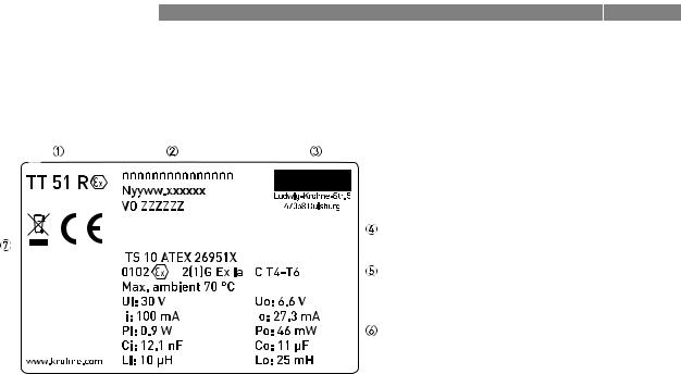
2.2.2 Nameplate for rail-mount transmitter |
|
|
||||||||||
|
|
|
|
|
|
|
|
|
|
|
|
|
|
|
|
|
|
|
|
|
|
|
|
|
|
|
|
|
|
|
|
|
|
|
|
|
|
|
|
|
|
|
|
|
|
|
|
|
|
|
|
|
|
|
|
|
|
|
|
|
|
|
|
|
|
|
|
|
|
|
|
|
|
|
|
|
|
|
|
|
|
|
|
|
|
|
|
|
|
|
|
|
|
|
|
|
|
|
|
|
|
|
|
|
|
|
|
|
|
|
|
|
|
|
|
|
|
|
|
|
|
|
|
|
|
|
|
|
|
|
|
|
|
|
|
|
|
|
|
|
|
|
Figure 2-3: Example for nameplate
1Product name
2Part number, serial number and batch number
3Manufacturer and address
4Printable field, sensor configuration
5Technical data
6Electrical data for output
7CE marking (EC conformity), electronic/electric device waste marking and SIL2 marking
12 |
www.krohne.com |
09/2010 - 4000754201 - MA TT 51 R01 en |

|
|
INSTALLATION 3 |
|
TT 51 SERIES |
|
|
|
|
3.1 Notes on installation
INFORMATION!
Inspect the cartons carefully for damage or signs of rough handling. Report damage to the carrier and to the local office of the manufacturer.
INFORMATION!
Check the packing list to check if you received completely all that you ordered.
INFORMATION!
Look at the device nameplate to ensure that the device is delivered according to your order. Check for the correct supply voltage printed on the nameplate.
3.2 In-head transmitter
These transmitters are intended for installation in DIN B connection heads or larger. The large Ø7 mm / 0.28" center hole facilitates the electrical connection of the measurement sensor and the installation. For detailed information refer to the chapter "Dimensions and weights".
Figure 3-1: Connection head installation kit
1M4 screw
2Spring
3Lock washer
4Pt100
5Protective tube
DANGER!
The TT 51 C transmitter is optionally available in a non-incendive version (zone 2) and in an intrinsically safe version (zone 0, 1 and 2) for installation in potentially explosive atmospheres. The intrinsically safe version must be supplied by an intrinsically safe power supply unit or Zener barrier placed outside of the potentially explosive zone.
The Ex transmitter must be installed in a housing with the protection rating IP20 or better according to EN 60529 / IEC 60529.
09/2010 - 4000754201 - MA TT 51 R01 en |
www.krohne.com |
13 |

3 INSTALLATION |
TT 51 SERIES |
|
INFORMATION!
The TT 51 C transmitter has been developed for an ambient temperature of
-40...+85°C / -40...+185°F. Please also note that the ambient temperature is also dependent on the temperature category. For detailed information refer to Ex data of the ambient temperature. The process temperature is also transferred to the transmitter housing via the protective tube. If the process temperature is close to or exceeds the maximum specified process temperature, then the temperature in the transmitter housing can rise above the maximum permissible ambient temperature. Always check that the ambient temperature where the transmitter is installed is always within the permissible range. One way to decrease heat transfer via the protective tube is to make the protective tube longer or in general to install the transmitter farther away from the heat source. The same safety measures can be taken if the temperature is below the specified minimum temperature.
3.3 Rail-mount transmitter
These transmitters are intended for installation on a rail according to DIN 50022.
Figure 3-2: Rail installation
1 Fix the upper part of the transmitter onto the rail.
2Press the lower part of the transmitter against the rail.
3To remove the transmitter, use a screwdriver to bend the locking device using a small screwdriver. Carefully pull the transmitter in the forward direction.
14 |
www.krohne.com |
09/2010 - 4000754201 - MA TT 51 R01 en |
|
|
ELECTRICAL CONNECTIONS 4 |
|
TT 51 SERIES |
|
|
|
|
4.1 Safety instructions
DANGER!
All work on the electrical connections may only be carried out with the power disconnected. Take note of the voltage data on the nameplate!
DANGER!
Observe the national regulations for electrical installations!
DANGER!
The transmitter is protected against polarity reversal. No damage will occur to the device if the polarity of the supply voltage is switched. The output will then indicate 0 mA.
DANGER!
The TT 51 C / TT 51 R are optionally available in a non-incendive version for use in potentially explosive atmosphere zone 2. For zone 2 applications a class 2 power supply placed in safe area is needed. In other potentially explosive areas, the intrinsically safe versions must be used. The TT 51 C (intrinsically safe) can be installed in potentially hazardous area zone 0, 1 and 2. The TT 51 R (intrinsically safe) can be installed in potentially hazardous area zone 1 and 2 and the input may be connected to zone 0.
The intrinsically safe versions must be supplied by an intrinsically safe power supply unit or Zener barrier placed outside of the potentially explosive zone.
WARNING!
Observe without fail the local occupational health and safety regulations. Any work done on the electrical components of the measuring device may only be carried out by properly trained specialists.
INFORMATION!
Look at the device nameplate to ensure that the device is delivered according to your order. Check for the correct supply voltage printed on the nameplate.
4.2 Electrical connections of in-head transmitter
The input and output signals and the power supply must be connected in accordance with the following illustrations. The transmitter is easy to install with the connection head installation kit. To avoid measuring errors, all cables must be connected properly and the screws tightened correctly.
09/2010 - 4000754201 - MA TT 51 R01 en |
www.krohne.com |
15 |

4 ELECTRICAL CONNECTIONS |
|
|
|
|
|
|
|
|
|
|
|
|
|
|
|
|
|
|
|
|
|
|
|||||||||||||||||||||
|
|
|
|
|
|
|
|
|
|
|
|
|
|
|
|
|
|
|
TT 51 SERIES |
|
|||||||||||||||||||||||
|
|
|
|
|
|
|
RTD and potentiometer measurement |
|
|
|
|
|
|
|
|
|
|
|
|
|
|
|
|
|
|||||||||||||||||||
|
|
|
|
|
|
|
|
|
|
|
|
|
|
|
|
|
|
|
|
|
|
|
|
||||||||||||||||||||
|
|
|
|
|
|
|
|
|
|
|
|
|
|
|
|
|
|
|
|
|
|
|
|
|
|
|
|
|
|
|
|
|
|
|
|
|
|
|
|
|
|
|
|
Pt100…Pt1000, Ni100, Ni120, Cu10 |
Pt100…Pt1000, Ni100, Ni120, Cu10 |
Pt100…Pt1000, Ni100, Ni120, Cu10 |
|||||||||||||||||||||||||||||||||||||||||
2-wire connection |
3-wire connection |
4-wire connection |
|||||||||||||||||||||||||||||||||||||||||
|
|
|
|
|
|
|
|
|
|
|
|
|
|
|
|
|
|
|
|
|
|
|
|
|
|
|
|
|
|
|
|
|
|
|
|
|
|
|
|
|
|
|
|
|
|
|
|
|
|
|
|
|
|
|
|
|
|
|
|
|
|
|
|
|
|
|
|
|
|
|
|
|
|
|
|
|
|
|
|
|
|
|
|
|
|
|
|
|
|
|
|
|
|
|
|
|
|
|
|
|
|
|
|
|
|
|
|
|
|
|
|
|
|
|
|
|
|
|
|
|
|
|
|
|
|
|
|
|
|
|
|
|
|
|
|
|
|
|
|
|
|
|
|
|
|
|
|
|
|
|
|
|
|
|
|
|
|
|
|
|
|
|
|
|
|
|
|
|
|
|
|
|
|
|
|
|
|
|
|
|
|
|
|
|
|
|
|
|
|
|
|
|
|
|
|
|
|
|
|
|
|
|
|
|
|
|
|
|
|
|
|
|
|
|
|
|
|
|
|
RTD, redundant sensor elements |
RTD, redundant sensor elements |
Resistance, 2-wire connection |
|||||||||||||||||||||||||||||||||||||||||||
2 x 3-wire connection |
2 x 2-wire connection |
|
|
|
|
|
|
|
|
|
|
|
|
|
|||||||||||||||||||||||||||||||
|
|
|
|
|
|
|
|
|
|
|
|
|
|
|
|
|
|
|
|
|
|
|
|
|
|
|
|
|
|
|
|
|
|
|
|
|
|
|
|
|
|
|
|
|
|
|
|
|
|
|
|
|
|
|
|
|
|
|
|
|
|
|
|
|
|
|
|
|
|
|
|
|
|
|
|
|
|
|
|
|
|
|
|
|
|
|
|
|
|
|
|
|
|
|
|
|
|
|
|
|
|
|
|
|
|
|
|
|
|
|
|
|
|
|
|
|
|
|
|
|
|
|
|
|
|
|
|
|
|
|
|
|
|
|
|
|
|
|
|
|
|
|
|
|
|
|
|
|
|
|
|
|
|
|
|
|
|
|
|
|
|
|
|
|
|
|
|
|
|
|
|
|
|
|
|
|
|
|
|
|
|
|
|
|
|
|
|
|
|
|
|
|
|
|
|
|
|
|
|
|
|
|
|
|
|
|
|
|
|
|
|
|
|
|
|
|
|
|
|
|
|
|
|
|
|
|
|
|
|
|
|
|
|
|
|
|
|
|
|
|
|
|
|
|
|
|
|
|
|
|
|
|
|
|
|
|
|
|
|
|
|
|
|
|
|
|
|
|
|
|
|
|
|
|
|
Resistance, 3-wire connection |
Resistance, 4-wire connection |
Potentiometer, 3-wire connection |
||||||||||||||||||||||||||||||||||||||
|
|
|
|
|
|
|
|
|
|
|
|
|
|
|
|
|
|
|
|
|
|
|
|
|
|
|
|
|
|
|
|
|
|
|
|
|
|
|
|
|
|
|
|
|
|
|
|
|
|
|
|
|
|
|
|
|
|
|
|
|
|
|
|
|
|
|
|
|
|
|
|
|
|
|
|
|
|
|
|
|
|
|
|
|
|
|
|
|
|
|
|
|
|
|
|
|
|
|
|
|
|
|
|
|
|
|
|
|
|
|
|
|
|
|
|
|
|
|
|
|
|
|
|
|
|
|
|
|
|
|
|
|
|
|
|
|
|
|
|
|
|
|
|
|
|
|
|
|
|
|
|
|
|
|
|
|
|
|
|
|
|
|
|
|
|
|
|
|
|
|
|
|
|
|
|
|
|
|
|
|
|
|
|
|
|
|
|
|
|
|
|
|
|
|
|
|
|
|
|
|
|
|
|
|
|
|
|
|
|
|
|
|
|
|
|
|
|
|
|
|
|
|
|
|
|
|
|
|
|
|
|
|
|
|
|
|
|
|
|
|
|
|
|
|
|
1 SmartSense wire
Thermocouple and voltage measurement
Thermocouple |
Thermocouple, redundant sensor |
Voltage |
|||||||||||||||||||||||||||||||||||||||||
|
|
|
|
|
|
|
|
|
|
|
|
|
|
elements |
|
|
|
|
|
|
|
|
|
|
|
|
|
|
|||||||||||||||
|
|
|
|
|
|
|
|
|
|
|
|
|
|
|
|
|
|
|
|
|
|
|
|
|
|
|
|
|
|
|
|
|
|
|
|
|
|
|
|
|
|
|
|
|
|
|
|
|
|
|
|
|
|
|
|
|
|
|
|
|
|
|
|
|
|
|
|
|
|
|
|
|
|
|
|
|
|
|
|
|
|
|
|
|
|
|
|
|
|
|
|
|
|
|
|
|
|
|
|
|
|
|
|
|
|
|
|
|
|
|
|
|
|
|
|
|
|
|
|
|
|
|
|
|
|
|
|
|
|
|
|
|
|
|
|
|
|
|
|
|
|
|
|
|
|
|
|
|
|
|
|
|
|
|
|
|
|
|
|
|
|
|
|
|
|
|
|
|
|
|
|
|
|
|
|
|
|
|
|
|
|
|
|
|
|
|
|
|
|
|
|
|
|
|
|
|
|
|
|
|
|
|
|
|
|
|
|
|
|
|
|
|
|
|
|
|
|
|
|
|
|
|
|
|
|
|
|
|
|
|
|
|
|
|
|
|
|
|
|
|
|
|
|
|
|
|
|
|
|
|
|
|
|
|
|
|
|
|
|
|
|
|
|
|
|
|
|
|
|
|
|
|
|
|
|
|
|
|
|
|
|
|
|
|
|
|
|
|
|
|
|
|
|
|
|
|
|
|
|
|
|
|
|
|
|
|
|
|
|
|
|
|
|
|
|
|
|
|
|
|
|
|
|
|
|
|
|
|
|
|
|
|
|
|
|
|
|
|
|
|
|
|
|
|
|
|
|
|
|
|
|
Voltage, redundant sensor elements |
Thermocouple with remote reference |
||||||||||||||||||||||||||||||||
|
|
|
|
|
|
|
|
|
|
|
|
|
|
|
|
|
|
junction compensation |
|||||||||||||||
|
|
|
|
|
|
|
|
|
|
|
|
|
|
|
|
|
|
|
|
|
|
|
|
|
|
|
|
|
|
|
|
|
|
|
|
|
|
|
|
|
|
|
|
|
|
|
|
|
|
|
|
|
|
|
|
|
|
|
|
|
|
|
|
|
|
|
|
|
|
|
|
|
|
|
|
|
|
|
|
|
|
|
|
|
|
|
|
|
|
|
|
|
|
|
|
|
|
|
|
|
|
|
|
|
|
|
|
|
|
|
|
|
|
|
|
|
|
|
|
|
|
|
|
|
|
|
|
|
|
|
|
|
|
|
|
|
|
|
|
|
|
|
|
|
|
|
|
|
|
|
|
|
|
|
|
|
|
|
|
|
|
|
|
|
|
|
|
|
|
|
|
|
|
|
|
|
|
|
|
|
|
|
|
|
|
|
|
|
|
|
|
|
|
|
|
|
|
|
|
|
|
|
|
|
|
|
|
|
|
|
|
|
|
|
|
|
|
|
|
|
|
|
|
|
|
|
|
|
|
|
|
|
|
|
|
|
|
1 SmartSense wire
16 |
www.krohne.com |
09/2010 - 4000754201 - MA TT 51 R01 en |
 Loading...