


© KROHNE 01/2006 |
7.02125.23.00 |
|
|
|
|
|
|
|
|
|
|
|
|
|
|
||
|
|
|
|
|
|
|
||
|
|
|
|
|
|
|
|
|
 CMD
CMD
Installation and operating instructions
DW 181 – 184
Standard, high-temperature, tropical and ATEX versions
Flow switches
Electromagnetic flowmeters
Variable area flowmeters
Mass flowmeters
Ultrasonic flowmeters
Vortex flowmeters
Flow controllers
Level measuring instruments
Pressure and temperature
Heat metering
Communications technology
Switches, counters, displays and recorders
Engineering systems & solutions

Table of contents
General advice on safety…………………………………………………………………………..4 Standards / Approvals…………………………………………………………………………….. 4 Ex safety instructions………………………………………………………………………………4 Handling……………………………………………………………………………………………… 4 Product liability and warranty……………………………………………………………………. 5 Items included with supply………………………………………………………………………..5 Documentation supplied………………………………………………………………………….. 5 Official approvals and certificates………………………………………………………………. 5 Principle components……………………………………………………………………………... 6 Equipment labels…………………………………………………………………………………… 7 Type code……………………………………………………………………………………………. 8 1 Mechanical Installation……………………………………………………………………… 9
1.1Positioning the flow switch……………………………………………………………………. 9
1.2Installation in hazardous areas (Ex applications)………………………………………….. 9
1.3Connecting the DW 18 to the pipe……………………………………………………………9
1.4Flow direction…………………………………………………………………………………...9
2Electrical Connections…………………………………………………………………….. 10
3Commissioning………………………………………………………………………………11
3.1General notes………………………………………………………………………………… 11
3.2Adjusting the limit switches - standard and EEx ia flow switch versions………………. 11
3.2.1Type G indicator……………………………………………………………………………. 11
3.2.2Type A indicator…………………………………………………………………………..... 12
3.3 Adjusting the limit switches - EEx d flow switch version………………………………….12 3.3.1 MS 12/BRX switch…………………………………………………………………………. 12
4 Display………………………………………………………………………………………... 13
4.1Local Flow indication………………………………………………………………………… 13
4.2Limit Switches………………………………………………………………………………… 13
4.3EEx d version………………………………………………………………………………….14
4.4High-temperature version (KROHNE temperature class H3, non-EEx)………………...15
4.5Tropical version (non-EEx)………………………………………………………………….. 15
2 |
Installation and operating instructions DW 181 - 184 |

5 Service………………………………………………………………………………………... 16
5.1Maintenance………………………………………………………………………………….. 16
5.2Exploded view of instruments………………………………………………………………. 16
5.3Spare parts…………………………………………………………………………………….18
5.4Inspection procedure………………………………………………………………………… 21
5.4.1Inspection procedure: measuring assembly…………………………………………….. 21
5.4.2Inspection procedure: housing (DW181 & DW182 models)…………………………... 21
5.5 Basic servicing procedures…………………………………………………………………..22
5.5.1Changing the position of the dial on the type A indicator……………………………… 22
5.5.2Removing the display assembly: operating faults in the housing DW18x Std /EExia flow controllers equipped with type G or A indicators……………………………………….. 23
5.5.3Cleaning the springs or changing the measuring system sub-assembly……………..24
5.5.4Changing gaskets in DW 183 flow controllers…………………………………………. 24
6 Technical Data………………………………………………………………………………. 25
6.1Flow range table by flow range code………………………………………………………. 28
6.2Instrument version materials………………………………………………………………... 30
7Dimensions and Weights…………………………………………………………………..31
8Measuring Principle…………………………………………………………………………36
8.1Measuring systems…………………………………………………………………………...36
8.2DW 183………………………………………………………………………………………...36
Appendix A: Declaration of conformity: CE…………………………………………………..37
Appendix B: If you need to return a device for testing or repair to KROHNE…………. 38
Installation and operating instructions DW 181 - 184 |
3 |
General advice on safety
This manual gives a complete set of instructions for the installation, operation and maintenance of the standard and ATEX versions of the DW 18 flow switches. DW 18 flow switches must be used with liquids that do not have any gas pockets. Special regulations are applicable to the use of equipment in hazardous locations, and these are described in this booklet. Data is supplied on explosion protection.
Assembly, installation, commissioning and maintenance of equipment in hazardous areas must only be carried out by qualified personnel with relevant explosion protection training.
Standards / Approvals
DW 18 flow switches meet the protection requirements of Directive 89/336/EEC in conjunction with EN 50081-1 and EN 50082-2, and Directives 73/23/EEC and 93/68/EEC in conjunction with EN 61010-1, and also bear the
CE symbol.
These instruments, when ordered with the appropriate options, are certified for use in hazardous locations by the INERIS certification agency under INERIS 03ATEX0045X. They respect the Health & Safety regulations in force by conforming to EN 50014 (+ A1 & 2), EN 50018, EN 50020, EN50284, EN 50281-1-1 (+ A1) and EN 13463-1.
Ex safety instructions
The DW 18 flow switch series are suitable for monitoring flow of liquid in pipes in hazardous areas. They may be approved for use in explosive atmospheres of all flammable substances in Gas Group IIC in Zone 1 and applications requiring Category 2 equipment for EEx d applications and Gas Group IIC in Zone 0 requiring Category 1 equipment with an intrinsically-safe power supply for
EEx ia applications.
Ex Equipment Category Definitions
Category 1 G/D – instruments: for intrinsically-safe applications
The signal converter for the limit switch options and the measuring components are located in hazardous areas requiring instruments qualified as being category 1. The G/D rating states that the instrument is qualified for gas and dust environments. EEx ia-approved devices must be used with a certified intrinsically-safe power supply.
Category 2 G/D – instruments: for applications using the EEx d-rated explosion-proof box
The signal converter for the limit switch options and the measuring components are located in hazardous areas requiring instruments qualified as being category 2. The G/D rating states that the instrument is qualified for gas and dust environments.
Handling
The device weighs between approx. 2 kg (4.5 lb) and 14 kg (30 lb). Carry using both hands to lift the device carefully by the tube. If necessary, use lifting gear.
Avoid hard blows, jolts, impacts, etc. when handling the DW 18.
4 |
Installation and operating instructions DW 181 - 184 |

Product liability and warranty
The DW 18 flow meter is designed solely for measuring the flow rate of liquids without any gas pocket. Special codes and regulations apply to its use in hazardous areas.
Responsibility as to suitability and intended use of these level gauges rests solely with the user. Improper installation and operation of our level gauges may lead to loss of warranty.
In addition, the "General conditions of sale", forming the basis of the purchasing contract, are applicable.
If you need to return the level gauge to the manufacturer or supplier, please refer to the information given in Appendix B.
Items included with supply
The scope of supply encompasses, in the version ordered:
•Flow meter
Documentation supplied
•Installation and operating instructions (this manual) including description of special versions and functions.
Official approvals and certificates
Application |
Approved by |
Instrument version |
Certification mark |
ATEX certification |
INERIS |
DW 18 TYPE 18. |
Certificate no. |
|
|
|
INERIS 03ATEX0045X* |
|
|
|
|
*This EC-type Examination Certificate is available in KROHNE’s download centre on http://www.krohne.com/.
Installation and operating instructions DW 181 - 184 |
5 |
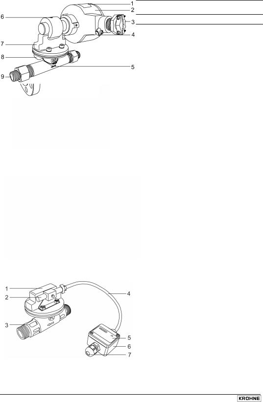
Principle components
DW 18 Standard or EEx ia version
1 Indicator type G (linear scale) or A (dial)
2 Equipment label*
3 Flange (illustrated) or screwed connection
4 Indicator cover locking pin
5 Flow direction arrow (DW183/4)
6 Wiring compartment cover
7 Gland (plugged)
8 Cable fitting (PG 13.5)
9 Measuring tube
DW 18 EEx d version
1 Equipment labels*
2 MS 12/BRX switch housing
3 Cable fitting (to be supplied by the customer)
4 PE terminal
5 Flow direction arrow (on measuring tube for DW181/2)
6 Socket set screw for adjusting switch position
7 Pressure housing
8 Equipment dog-tag (tag no., etc.)
9 Screw-on connection
DW 18 HT (H3) version
1 Pressure housing
2 Switch sheathed in a PTFE cartridge
3 Measuring tube
4 Electric cable in fibre glass sheathing
5 MS 14 switch information label
6 Wiring box
7 Cable fitting (PG 9)
* Equipment labels shown on next page
6 |
Installation and operating instructions DW 181 - 184 |

Equipment labels
Standard label (all devices)
1 Designation code acc. to order options list (e.g.V7BD1...)*
2 Type code
(e.g. DW181/C/011/B/G/KA/N/G1)**
3 Purchase order number
4 Factory serial number
5 Customer tag number
EEx ia supplementary information label (e.g. version K1 NO)
1 ATEX gas group and equipment category (e.g. II 1 GD)
2 Year built
3 ATEX certification code
4 Electrical safety values
5 Wiring diagram
6 Protection concept & gas group + sub-div. and temperature class (e.g. EEx ia IIC T3...T6)
EEx d supplementary information label (e.g. version NC)
1 Limit switch code
2 ATEX certification code
3 Year built
4 ATEX gas group and equipment category (e.g. II 1/2 GD)
5 Protection concept & gas group + sub-div. and temperature class (e.g. EEx d IIC T3...T6)
6 Factory serial number
7 Maximum switching capacity
8 Wiring diagram
*See DW 181-184 Data sheet for a list of order options and designation codes
**See type code definitions on the next page
Installation and operating instructions DW 181 - 184 |
7 |

Type code
Refer to the standard device label, item 2 on the previous page.
DW . . . / . / . . . . / . . / . / . . . / . . / . .
|
1 |
2 |
3 |
4 |
5 |
6 |
7 |
8 |
|
|
|
|
|
|
|
|
|||
Type code element |
|
|
Code |
|
|
Code definition |
|||
1 |
Type series |
|
|
|
181 |
|
|
For horizontal or vertical pipes, screw |
|
|
|
|
|
|
|
|
|
|
connection G¾…G2, measuring system C or |
|
|
|
|
|
|
|
|
|
E* |
|
|
|
|
|
|
182 |
|
|
For horizontal or vertical pipes, flange |
|
|
|
|
|
|
|
|
|
connection DN15…65 and ½”…2”-150 lbs, |
|
|
|
|
|
|
|
|
|
measuring system C or E* |
|
|
|
|
|
|
183 |
|
|
For horizontal or vertical pipes, flange |
|
|
|
|
|
|
|
|
|
connections DN65…200 and 3”…8”-150 lbs, |
|
|
|
|
|
|
|
|
|
measuring system P* |
|
|
|
|
|
|
184 |
|
|
For horizontal pipes (DN ≥250 or 10”, mounting |
|
|
|
|
|
|
|
|
|
flange DN150 PN16 or 6”-150 lbs, measuring |
|
|
|
|
|
|
|
|
|
system P* |
2 |
Measuring system |
|
|
C |
|
|
Measuring disc in tapered tube |
||
|
|
|
|
|
|
E |
|
|
Nozzle with baffle |
|
|
|
|
|
|
P |
|
|
Baffle in constant diameter pipe |
3 |
Code number |
|
|
|
011 - 204 |
|
See section 7.1: Flow range table for the |
||
|
|
|
|
|
|
|
|
|
characteristics of each code number. |
4 |
Material of construction |
|
|
B |
|
|
Bronze |
||
- see also section 7.2 |
|
|
RR |
|
|
Stainless steel (SS) 316 L |
|||
|
|
|
|
|
|
R |
|
|
SS 316L measuring tube, steel connection |
|
|
|
|
|
|
N |
|
|
Steel |
5 |
Indicator system |
|
|
|
G |
|
|
Linear scale marks |
|
|
|
|
|
|
|
A |
|
|
Dial with flow units |
6 |
Limit switches |
|
|
|
K1 |
|
|
1 NC or 1 NO switch** |
|
|
|
|
|
|
|
K2 |
|
|
1 NC and 1 NO switch** |
|
|
|
|
|
|
KV1 |
|
|
Amplifier relay: 1 change-over switch** |
|
|
|
|
|
|
KV2 |
|
|
Amplifier relay: 2 change-over switches** |
7 |
Application field |
|
|
|
N |
|
|
Normal locations |
|
|
|
|
|
|
|
Ex d |
|
|
Hazardous locations |
|
|
|
|
|
|
Ex ia |
|
|
Intrinsically-safe applications |
8 |
Connection |
|
|
|
G ¾…G2 |
|
Pipe thread |
||
|
|
|
|
|
|
DN15…200 |
|
Flange connection |
|
|
|
|
|
|
|
(½”…8”) |
|
|
|
*Refer to section 9.1
**Bistable.
NO is a “normally open” switch during operation (closed switch when flow is decreasing) NC is a “normally closed” switch during operation (closed switch when flow is increasing).
8 |
Installation and operating instructions DW 181 - 184 |
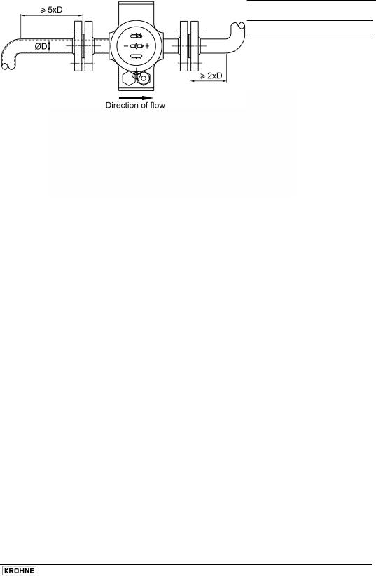
1 Mechanical Installation
1.1Positioning the flow switch
No obstacles along the pipe within five diameters (D) upstream and two diameters downstream of the instrument.
1.2Installation in hazardous areas (Ex applications)
Read all instructions referring to flow switches in hazardous locations before installation.
Check that the flange, gasket and other materials in contact with the product are compatible. Refer to the information given on the converter nameplate, the flange markings and specifications given in the ATEX approval certificate.
1.3Connecting the DW 18 to the pipe
•Before installation, clean the piping to remove any dust or weld debris.
•Fit the instrument on the pipe with the arrow on the housing pointing in the direction of flow.
•Flange connections: ensure that the gaskets are in place, flange facings are aligned and parallel and that the bolts have been tightened with the amount of torque specified in European or local (if outside the E.U.) standards.
1.4Flow direction
The DW 183 and DW 184 can be installed in any position on the piping. However, the position of installation and the flow direction must be indicated in the customer order (i.e. up, down, left to right and right to left) as the weight of the baffle disc is taken into account when calibrating the instrument. Flow direction must be indicated for DW 181 and DW 182 instruments equipped with type A indicators.
The DW 184 is used for high-velocity or turbulent flows in pipes with diameters greater than DN250. A special device, called a stilling well, is immersed in the liquid flow and channels the fluid through a tube in which the disc moves, secured to the end of a rigid support. This reinforced pivot enables the flow switch to be used in difficult conditions.
These instruments are only supplied with an index display (indicator type “G”) and switches. They are not equipped with a graduated dial. The heights of the connection piece indicated for the production of the mating flange must be respected.
Installation and operating instructions DW 181 - 184 |
9 |
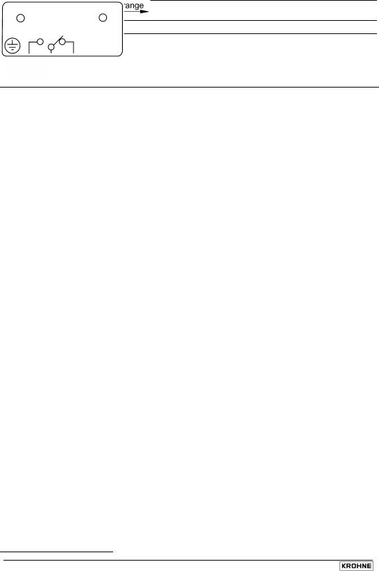
2 Electrical Connections
Disconnect the power supply before opening the housing
•The electrical connection conforms to the standard EN61010-1, protection class 1 (for aluminium housing) or class 2 (for PVC housing), voltage category III, and interference degree 2.
•The DW range conforms to EMC directives NF EN 50 081.1 (Emission) and NF EN 50 082.2 (Immunity).
•It is obligatory to have a switching or circuit breaking device, following present regulations. The devices should completely isolate the unit and be easily accessible, close to the unit.
•Both the live (L) and neutral (N) wires should be protected by a fuse (4…6.3 A Time Lag). During the wiring procedure the ground wire should always be connected first (relevant only for aluminium housing).
•EEx ia versions must be used with a certified intrinsically-safe power supply.
N.B. Use of the unit outside the specifications detailed in this manual can compromise the safety measures designed into the unit. Always disconnect the power supply before accessing the terminals.
|
Number |
Switch |
|
|
|
|
|
|
|
|
|
|
|
of |
types |
|
|
|
|
|
|
|
|
|
|
|
Limit switch adjustable over entire range |
|||||||||||
|
switches |
|
||||||||||
|
|
Type |
|
|
|
|
|
|
|
|
A |
|
|
|
K1 |
|
|
|
|
|
|
|
|
|
|
|
1 |
|
|
|
|
|
|
|
|
|
|
|
|
|
|
|
|
|
|
|
|
|
|
|
|
|
Type |
|
|
|
|
|
|
|
|
B |
||
|
|
|
|
|
|
|
|
|
|
|||
|
|
|
|
|
|
|
|
|
|
|
|
|
|
|
K1 |
|
|
|
|
|
|
|
|
|
|
|
|
|
|
|
|
|
|
|
|
|
|
|
|
|
|
|
|
|
|
|
|
|
|
|
|
|
|
Type |
|
|
|
|
|
|
|
|
C |
|
|
|
|
|
|
|
|
|
|
|
|
|
|
|
|
K2 |
|
|
|
|
|
|
|
|
|
|
|
|
|
|
|
|
|
|
|
|
|
|
|
|
|
|
|
|
|
|
|
|
|
|
|
|
|
|
Type |
|
|
|
|
|
|
|
|
D |
|
|
|
|
|
|
|
|
|
|
|
|
|
|
|
|
K2 |
|
|
|
|
|
|
|
|
|
|
|
2 |
|
|
|
|
|
|
|
|
|
|
|
|
|
Type |
|
|
|
|
|
|
|
|
E |
|
|
|
|
|
|
|
|
|
|
|
|
|
|
|
|
K2 |
|
|
|
|
|
|
|
|
|
|
|
|
|
|
|
|
|
|
|
|
|
|
|
|
|
Type |
|
|
|
|
|
|
|
|
F |
|
|
|
|
|
|
|
|
|
|
|
|
|
|
|
|
K2 |
|
|
|
|
|
|
|
|
|
|
|
|
|
|
|
|
|
|
|
|
|
|
|
|
1 |
Type |
|
|
|
|
|
|
|
|
G |
|
|
|
|
|
|
|
|
|
|
|
|
||
|
|
KV1 |
|
|
|
|
|
|
|
|
|
|
|
|
|
|
|
|
|
|
|
|
|
|
|
|
1 |
Type |
|
|
|
|
|
|
|
|
H |
|
|
|
|
|
|
|
|
|
|
|
|
||
|
|
KV2 |
|
|
|
|
|
|
|
|
|
|
|
|
|
|
|
|
|
|
|
|
|
|
|
|
K1 |
Change |
|
|
|
|
|
|
|
|
|
|
|
|
|
|
|
|
|
|
|
|
|
||
|
+ |
over |
|
|
|
|
|
|
|
|
|
|
|
K2 |
(SPDT) |
|
|
|
|
|
|
|
|
|
|
|
|
|
|
|
|
|
|
|
|
|
|
|
|
|
|
|
|
|
|
|
|
|
|
|
|
10 |
Installation and operating instructions DW 181 - 184 |
3 Commissioning
3.1General notes
The flow switch is delivered pre-calibrated and ready for use. Open the valves slowly when starting operation.
3.2Adjusting the limit switches - standard and EEx ia flow switch versions
The limit switches can be adjusted individually over the entire measuring range. To adjust, remove the locking pin securing the cap and remove the cap.
3.2.1 Type G indicator
The limit switch adjustment is indicated by a green strip (normally closed switch) or a black strip (normally open switch) in a graduated window. For flow switches manufactured before September 1, 1991, the strips are red (normally closed switch) or orange (normally open switch).
Each graduation corresponds to 1/10 of the total measuring range, i.e. 35 l/h for a flow range of 50…400 l/h. This system enables the limit switch to be adjusted without having to circulate fluid in the pipe. It is only necessary to adjust the micrometer screw (item 2) in order to move the switch support (item 3) which has the coloured strip on its upper section.
“G” linear index indicator assembly
1 Index
2 Micrometer screw
3 Switch support
4 Switch
5 Control magnet
6 Following magnet
Installation and operating instructions DW 181 - 184 |
11 |

3.2.2 Type A indicator
The switch is adjusted by unlocking the adjustment screw (item 7) and repositioning the switch support arm (item 8).
“A” graduated dial indicator assembly
1 Pointer
2 Dial
3 Following magnet
4 Control magnet
5 Mechanism
6 Switch
7 Adjustment screw
8 Switch support
3.3Adjusting the limit switches - EEx d flow switch version
3.3.1 MS 12/BRX switch
The switch is adjusted by unscrewing the limit switch adjustment screw M8x10 (2) on top of the pressure housing with a 4mm hexagon key. The switch (in its metal sheath) may then be repositioned as required before retightening the screw. The original position is etched onto the sheath.
MS 12/BRX switch assembly
1 MS 12/BRX switch
2 Limit switch adjustment screw
3 Switch sheath
4 Switch magnet
5 Pressure housing
12 |
Installation and operating instructions DW 181 - 184 |
 Loading...