


 DWM 2000 D Operating instructions
DWM 2000 Electromagnetic Flowmeter with LCD Indicator

Contents
1 Display data in operating mode…………………………………………………………………..3
2 Functions of the LCD indicator for the DWM 2000 D ………………………………………..4
2.1Programmable parameters ………………………………………………………………………..4
2.1.1Flow calibration ………………………………………………………………………4
2.1.2Current output adjustment ………………………………………………………….4
2.1.3Time constant ………………………………………………………………………..4
2.2 Electronics module checks ……………………………………………………………………..5
2.3Programming structure (Software n° 1.02) ………………………………………………………5
2.3.1User interface buttons ………………………………………………………………5
2.3.2Menu naviagation ……………………………………………………………………6
2.3.3Summary of programming menus …………………………………………………8
2.4Parameters stored in the EEPROM (menu 2.4.3) …………………………………………….10
2.5Error message list ………………………………………………………………………………..11
2 |
Operating Instructions DWM 2000 D |
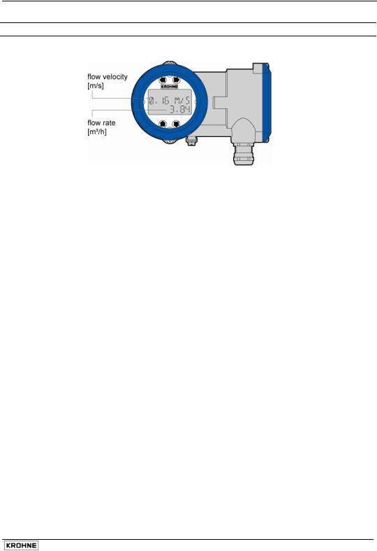
1 Display data in operating mode
Operating Instructions DWM 2000 D |
3 |

2 Functions of the LCD indicator for the DWM 2000 D
2.1Programmable parameters
2.1.1 Flow calibration
The GK can be modified in menu 2.1.3 in order to obtain the maximum accuracy at operating conditions. A field calibration requires an accurate reference of velocity. The meter recalibration (GK modification) is also recommended after an exchange of electronics module.
The value of the new calibration constant (GK new) can be calculated as follows:
GKnew = GKold x Va
Vm
with:
Va = actual velocity
Vm = measured velocity (reference value)
2.1.2 Current output adjustment
The minimum value (i0%) and the maximum value (i100%) of the current output at normal operating conditions can be adjusted from menus 2.2.2. and 2.2.3.
The actual values of the i0% and the i100% must be measured with an accurate milliammeter in a 4...20 mA loop.
i0% must be in the range 3....12 mA. The factory setting is 4 mA. i100% must be in the range 12....21 mA. The factory setting is 20 mA.
2.1.3 Time constant
The time constant value can be set in menu 2.2.4. This value represents the time needed to detect 63% of a simulated flow rate instantaneously raised from 0 to 100%. Time constant range : 5, 10, 15, 20, 25, 30, 50 m.
4 |
Operating Instructions DWM 2000 D |
 Loading...