


SUMMIT 8800 Handbook
Flow Computer
Volume 3: Configuration
© KROHNE 08/2013 - MA SUMMIT 8800 Vol 3 R02 en
|
IMPRINT |
|
|
SUMMIT 8800 |
|
|
|
|
All rights reserved. It is prohibited to reproduce this documentation, or any part thereof, without the prior written authorisation of KROHNE Messtechnik GmbH.
Subject to change without notice.
Copyright 2013 by
KROHNE Messtechnik GmbH - Ludwig-KROHNE-Str. 5 - 47058 Duisburg (Germany)
2 |
www.krohne.com |
08/2013 - MA SUMMIT 8800 Vol3 R02 en |

|
CONTENTS |
|
SUMMIT 8800 |
|
|
|
|
|
1 About this book |
12 |
1.1 Volumes.............................................................................................................................. |
12 |
1.2 Content Volume 1............................................................................................................... |
12 |
1.3 Content Volume 2............................................................................................................... |
12 |
1.4 Content Volume 3............................................................................................................... |
13 |
1.5 Information in this handbook............................................................................................. |
13 |
2 General Information |
14 |
2.1 Software versions used for this guide............................................................................... |
14 |
2.2 Terminology and Abbreviations......................................................................................... |
14 |
2.3 General Controls and Conventions.................................................................................... |
15 |
2.4 ID Data Tree........................................................................................................................ |
16 |
2.4.1 Type of data............................................................................................................................... |
17 |
2.4.2 Colour codes............................................................................................................................. |
18 |
2.4.3 ID Lookup.................................................................................................................................. |
19 |
2.5 Specific Requirements for Meters and Volume Convertors.............................................. |
19 |
2.5.1 Numbering formats.................................................................................................................. |
19 |
2.5.2 Alarms....................................................................................................................................... |
19 |
2.5.3 Optional consequences............................................................................................................. |
20 |
3 CONFIGURATOR SOFTWARE |
21 |
4 DATE & TIME |
23 |
4.1 Initial setting of date and time .......................................................................................... |
23 |
4.2 SNTP Time Synchronisation.............................................................................................. |
24 |
4.3 Manually change date and time ........................................................................................ |
25 |
5 DATA LOGGING |
27 |
5.1 Alarm and audit log security.............................................................................................. |
27 |
5.2 Alarm log............................................................................................................................ |
28 |
5.3 Audit trail log...................................................................................................................... |
28 |
5.3.1 Audit log extension.................................................................................................................... |
29 |
5.4 Data log.............................................................................................................................. |
31 |
5.4.1 Access to data log..................................................................................................................... |
34 |
08/2013 - MA SUMMIT 8800 Vol3 R02 en |
www.krohne.com |
3 |

|
CONTENTS |
|
|
SUMMIT 8800 |
|
|
|
|
6 DISPLAY AND WEB ACCESS |
36 |
6.1 System pages..................................................................................................................... |
36 |
6.2 User defined pages............................................................................................................ |
40 |
6.3 Display................................................................................................................................ |
40 |
6.3.1 Main menu & submenus........................................................................................................... |
41 |
6.3.2 Display page & items................................................................................................................ |
44 |
6.3.3 Set the page type...................................................................................................................... |
45 |
6.4 Security / edit mode........................................................................................................... |
49 |
6.4.1 Users & submenus................................................................................................................... |
49 |
6.4.2 Display page and items............................................................................................................. |
50 |
6.5 Supervisor Mode................................................................................................................ |
51 |
6.6 Alarm/Audit Security Configuration.................................................................................. |
53 |
6.7 Mimic Diagrams................................................................................................................. |
53 |
6.7.1 Mimic diagram selection.......................................................................................................... |
54 |
6.7.2 New mimic item........................................................................................................................ |
55 |
6.7.3 Configure mimic item............................................................................................................... |
56 |
6.8 Display templates.............................................................................................................. |
64 |
6.8.1 Template selection.................................................................................................................... |
65 |
6.8.2 New template item................................................................................................................... |
66 |
6.9 3D Graphs........................................................................................................................... |
74 |
6.9.1 Graph selection......................................................................................................................... |
76 |
6.9.2 Graph settings and options....................................................................................................... |
76 |
6.9.3 3D graph profile........................................................................................................................ |
78 |
6.10 Keyboard Configuration................................................................................................... |
80 |
6.11 Default.............................................................................................................................. |
82 |
6.12 Translation to local language.......................................................................................... |
83 |
6.12.1 Importing a language file........................................................................................................ |
85 |
6.12.2 Change a language in Excel.................................................................................................... |
86 |
6.13 Web access....................................................................................................................... |
88 |
7 REPORTING |
89 |
7.1 Serial ticket printing.......................................................................................................... |
90 |
7.1.1 Serial port settings................................................................................................................... |
90 |
7.1.2 Print jobs................................................................................................................................... |
91 |
7.1.3 Configure report........................................................................................................................ |
93 |
7.1.4 Format the items...................................................................................................................... |
94 |
7.1.5 Add statistics............................................................................................................................. |
96 |
7.1.6 Multiple pages........................................................................................................................... |
97 |
7.2 Ethernet reporting............................................................................................................. |
97 |
7.2.1 FTP protocol.............................................................................................................................. |
98 |
7.2.2 SMTP E-mail protocol............................................................................................................... |
98 |
7.2.3 Print jobs................................................................................................................................... |
99 |
7.2.4 Configure HTML report........................................................................................................... |
102 |
7.2.5 Configure XML Reports........................................................................................................... |
109 |
4 |
www.krohne.com |
08/2013 - MA SUMMIT 8800 Vol3 R02 en |

|
CONTENTS |
|
SUMMIT 8800 |
|
|
|
|
|
7.3 Downloadable ID or active data reports.......................................................................... |
117 |
7.3.1 Format the items.................................................................................................................... |
118 |
7.3.2 Read a report.......................................................................................................................... |
119 |
8 COMMUNICATION |
120 |
8.1 Type of protocols.............................................................................................................. |
120 |
8.1.1 Standard protocol.................................................................................................................... |
120 |
8.1.2 Meter protocols....................................................................................................................... |
120 |
8.1.3 Host protocols......................................................................................................................... |
120 |
8.2 Basic Communication setup............................................................................................ |
121 |
8.2.1 Port selection.......................................................................................................................... |
121 |
8.2.2 Basic RS 232/485 serial port settings.................................................................................... |
122 |
8.2.3 Basic Ethernet settings......................................................................................................... |
122 |
8.3 Modbus master................................................................................................................ |
123 |
8.3.1 Modbus master port selection and settings........................................................................... |
123 |
8.3.2 Modbus Master type................................................................................................................ |
124 |
8.3.3 Differential pressure meters.................................................................................................. |
125 |
8.3.4 Ultrasonic and Coriolis meters............................................................................................... |
126 |
8.3.5 Provers.................................................................................................................................... |
127 |
8.3.6 Gas chromatographs.............................................................................................................. |
128 |
8.3.7 Redundancy master................................................................................................................ |
130 |
8.3.8 Custom Modbus master.......................................................................................................... |
131 |
8.4 Modbus slave................................................................................................................... |
131 |
8.4.1 Modbus slave port selection and settings.............................................................................. |
132 |
8.4.2 Modbus slave addresses......................................................................................................... |
135 |
8.4.3 Parameters............................................................................................................................. |
136 |
8.5 Enron Modbus.................................................................................................................. |
139 |
8.5.1 Enron modbus settings:.......................................................................................................... |
139 |
8.5.2 Create logs.............................................................................................................................. |
140 |
8.5.3 Addressing scheme:.............................................................................................................. |
143 |
8.5.4 Define Modbus alarms............................................................................................................ |
145 |
8.6 Pemex Modbus................................................................................................................. |
146 |
8.6.1 Logs......................................................................................................................................... |
146 |
8.6.2 Addressing scheme................................................................................................................ |
146 |
8.7 Instromet Ultrasonic protocol.......................................................................................... |
147 |
8.8 Encoder protocol.............................................................................................................. |
148 |
8.9 CTE Protocol..................................................................................................................... |
149 |
8.10 DSfG Protocol................................................................................................................. |
152 |
8.11 SOAP protocol................................................................................................................ |
153 |
9 GENERAL INFORMATION |
154 |
9.1 Unit Identification............................................................................................................. |
154 |
9.2 Date and time................................................................................................................... |
154 |
9.3 Translation....................................................................................................................... |
155 |
08/2013 - MA SUMMIT 8800 Vol3 R02 en |
www.krohne.com |
5 |

|
CONTENTS |
|
|
SUMMIT 8800 |
|
|
|
|
9.4 Audit log........................................................................................................................... |
155 |
9.5 Settings............................................................................................................................ |
155 |
9.6 Product information......................................................................................................... |
156 |
9.7 Calculation code............................................................................................................... |
156 |
9.8 Factory acceptance test check......................................................................................... |
157 |
9.9 Security configuration...................................................................................................... |
159 |
9.10 ID report......................................................................................................................... |
161 |
9.11 Maintenance................................................................................................................... |
161 |
9.12 Formatting...................................................................................................................... |
162 |
9.13 Customs strings............................................................................................................. |
163 |
9.14 Minimum & maximum ID’s............................................................................................ |
164 |
9.15 Redundancy.................................................................................................................... |
166 |
9.16 Watchdog........................................................................................................................ |
166 |
9.17 Run-switching................................................................................................................ |
166 |
9.18 SOAP............................................................................................................................... |
166 |
9.19 Modbus time-out............................................................................................................ |
166 |
9.20 Modbus alarms.............................................................................................................. |
167 |
9.21 CTE Configuration.......................................................................................................... |
167 |
10 APPENDIX 1: SOFTWARE VERSIONS |
168 |
10.1 Versions/ Revisions........................................................................................................ |
168 |
10.2 Current versions............................................................................................................ |
168 |
10.2.1 Latest version 0.35.0.0.......................................................................................................... |
168 |
10.2.2 Approved version MID2.4.0.0................................................................................................ |
169 |
11 APPENDIX 2: TABLE OF LEGALLY-RELEVANT PARAMETERS |
170 |
12 APPENDIX 3: MODBUS COMMUNICATION PROTOCOL |
171 |
12.1 Number formats............................................................................................................ |
171 |
6 |
www.krohne.com |
08/2013 - MA SUMMIT 8800 Vol3 R02 en |

|
CONTENTS |
|
SUMMIT 8800 |
|
|
|
|
|
Figure 1 Example ID Tree . . . . . . . . . . . . . . . . . . . . . . . . . . . . . . . . . . . . . . . . . . . . . . . . . . . . . |
. |
17 |
Figure 2 ID lookup . . . . . . . . . . . . . . . . . . . . . . . . . . . . . . . . . . . . . . . . . . . . . . . . . . . . . . . . . . . |
. |
19 |
Figure 3 Configurator option selections . . . . . . . . . . . . . . . . . . . . . . . . . . . . . . . . . . . . . . . . . |
. |
21 |
Figure 4 Application firmware version. . . . . . . . . . . . . . . . . . . . . . . . . . . . . . . . . . . . . . . . . . |
. |
21 |
Figure 5 Main Configurator display .. . . . . . . . . . . . . . . . . . . . . . . . . . . . . . . . . . . . . . . . . . . . |
. |
22 |
Figure 6 Date & time and contract time selection . . . . . . . . . . . . . . . . . . . . . . . . . . . . . . . . . |
. |
23 |
Figure 7 SNTP Date & time general settings . . . . . . . . . . . . . . . . . . . . . . . . . . . . . . . . . . . . . |
. |
24 |
Figure 8 SNTP Date & time unicast settings.. . . . . . . . . . . . . . . . . . . . . . . . . . . . . . . . . . . . . |
. |
25 |
Figure 9 SNTP Date & time broadcast settings. . . . . . . . . . . . . . . . . . . . . . . . . . . . . . . . . . . |
. |
25 |
Figure 10 Manual Date & time settings. . . . . . . . . . . . . . . . . . . . . . . . . . . . . . . . . . . . . . . . . . |
. |
26 |
Figure 11 Manual Date & time adjustment. . . . . . . . . . . . . . . . . . . . . . . . . . . . . . . . . . . . . . . |
. |
26 |
Figure 12 Display security window. . . . . . . . . . . . . . . . . . . . . . . . . . . . . . . . . . . . . . . . . . . . . |
. |
27 |
Figure 13 Alarm log. . . . . . . . . . . . . . . . . . . . . . . . . . . . . . . . . . . . . . . . . . . . . . . . . . . . . . . . . . |
. |
28 |
Figure 14 Audit trail log. . . . . . . . . . . . . . . . . . . . . . . . . . . . . . . . . . . . . . . . . . . . . . . . . . . . . . |
. |
29 |
Figure 15 Audit log extension. . . . . . . . . . . . . . . . . . . . . . . . . . . . . . . . . . . . . . . . . . . . . . . . . . |
. |
30 |
Figure 16 Audit log select alarms. . . . . . . . . . . . . . . . . . . . . . . . . . . . . . . . . . . . . . . . . . . . . . |
. |
30 |
Figure 17 Audit log select variables.. . . . . . . . . . . . . . . . . . . . . . . . . . . . . . . . . . . . . . . . . . . . |
. |
31 |
Figure 18 Audit log options. . . . . . . . . . . . . . . . . . . . . . . . . . . . . . . . . . . . . . . . . . . . . . . . . . . . |
. |
31 |
Figure 19 Data logging. . . . . . . . . . . . . . . . . . . . . . . . . . . . . . . . . . . . . . . . . . . . . . . . . . . . . . . |
. |
32 |
Figure 20 Data log select variables . . . . . . . . . . . . . . . . . . . . . . . . . . . . . . . . . . . . . . . . . . . . . |
. |
32 |
Figure 21 Data log settings. . . . . . . . . . . . . . . . . . . . . . . . . . . . . . . . . . . . . . . . . . . . . . . . . . . . |
. |
33 |
Figure 22 Data log statistics. . . . . . . . . . . . . . . . . . . . . . . . . . . . . . . . . . . . . . . . . . . . . . . . . . . |
. |
33 |
Figure 23 Data log local log numbers . . . . . . . . . . . . . . . . . . . . . . . . . . . . . . . . . . . . . . . . . . . |
. |
34 |
Figure 24 Data log ID’s for FTP printing with log record selection.. . . . . . . . . . . . . . . . . . . |
. |
35 |
Figure 25 Data log ID’s for modbus with index selection.. . . . . . . . . . . . . . . . . . . . . . . . . . . |
. |
35 |
Figure 26 Display, set the correct engineering units. . . . . . . . . . . . . . . . . . . . . . . . . . . . . . . |
. |
36 |
Figure 27 Alarm and audit log. . . . . . . . . . . . . . . . . . . . . . . . . . . . . . . . . . . . . . . . . . . . . . . . . |
. |
37 |
Figure 28 Edit mode and system information.. . . . . . . . . . . . . . . . . . . . . . . . . . . . . . . . . . . . |
. |
38 |
Figure 29 Settings, display settings and touchscreen calibration . . . . . . . . . . . . . . . . . . . . |
. |
39 |
Figure 30 Display main page. . . . . . . . . . . . . . . . . . . . . . . . . . . . . . . . . . . . . . . . . . . . . . . . . . |
. |
40 |
Figure 31 Configurator main menu & submenu.. . . . . . . . . . . . . . . . . . . . . . . . . . . . . . . . . . |
. |
41 |
Figure 32 Display main menu & submenu. . . . . . . . . . . . . . . . . . . . . . . . . . . . . . . . . . . . . . . |
. |
41 |
Figure 33 New menu, select template.. . . . . . . . . . . . . . . . . . . . . . . . . . . . . . . . . . . . . . . . . . |
. |
42 |
Figure 34 Edit a menu item.. . . . . . . . . . . . . . . . . . . . . . . . . . . . . . . . . . . . . . . . . . . . . . . . . . . |
. |
43 |
Figure 35 Bit map editor. . . . . . . . . . . . . . . . . . . . . . . . . . . . . . . . . . . . . . . . . . . . . . . . . . . . . . |
. |
43 |
Figure 36 Import bit map. . . . . . . . . . . . . . . . . . . . . . . . . . . . . . . . . . . . . . . . . . . . . . . . . . . . . |
. |
44 |
Figure 37 Configure display page.. . . . . . . . . . . . . . . . . . . . . . . . . . . . . . . . . . . . . . . . . . . . . . |
. |
44 |
Figure 38 Display item details . . . . . . . . . . . . . . . . . . . . . . . . . . . . . . . . . . . . . . . . . . . . . . . . . |
. |
45 |
Figure 39 Display page based on 8 centre template. . . . . . . . . . . . . . . . . . . . . . . . . . . . . . . |
. |
46 |
Figure 40 Display page based on VU template. . . . . . . . . . . . . . . . . . . . . . . . . . . . . . . . . . . . |
. |
46 |
Figure 41 Display page based on a mimic. . . . . . . . . . . . . . . . . . . . . . . . . . . . . . . . . . . . . . . . |
. |
47 |
Figure 42 Display page based on a mimic. . . . . . . . . . . . . . . . . . . . . . . . . . . . . . . . . . . . . . . . |
. |
47 |
Figure 43 Display page based on log data (list).. .. .. .. .. .. .. .. .. .. .. .. .. .. .. .. .. .. .. .. .. .. .. .. .. .. .. .. .. .. .. .. .. .. .. |
.. |
47 |
Figure 44 Display page based on log data (Graph). . . . . . . . . . . . . . . . . . . . . . . . . . . . . . . . . |
. |
48 |
Figure 45 Display page based on a X-Y-Z graph.. . . . . . . . . . . . . . . . . . . . . . . . . . . . . . . . . . |
. |
48 |
Figure 46 Configurator security window. . . . . . . . . . . . . . . . . . . . . . . . . . . . . . . . . . . . . . . . . |
. |
49 |
Figure 47 Configurator users & submenus.. . . . . . . . . . . . . . . . . . . . . . . . . . . . . . . . . . . . . . |
. |
49 |
Figure 48 Summit users & submenu. . . . . . . . . . . . . . . . . . . . . . . . . . . . . . . . . . . . . . . . . . . . |
. |
50 |
Figure 49 Edit users. . . . . . . . . . . . . . . . . . . . . . . . . . . . . . . . . . . . . . . . . . . . . . . . . . . . . . . . . |
. |
50 |
Figure 50 Same page in normal and in supervisor mode . . . . . . . . . . . . . . . . . . . . . . . . . . . |
. |
51 |
Figure 51 Setup supervisor mode . . . . . . . . . . . . . . . . . . . . . . . . . . . . . . . . . . . . . . . . . . . . . . |
. |
52 |
Figure 52 Summit supervisor mode login and logout . . . . . . . . . . . . . . . . . . . . . . . . . . . . . . |
. |
53 |
Figure 53 Mimic display definition. . . . . . . . . . . . . . . . . . . . . . . . . . . . . . . . . . . . . . . . . . . . . . |
. |
54 |
Figure 54 Create a mimic display canvas . . . . . . . . . . . . . . . . . . . . . . . . . . . . . . . . . . . . . . . . |
. |
54 |
Figure 55 New mimic display .. . . . . . . . . . . . . . . . . . . . . . . . . . . . . . . . . . . . . . . . . . . . . . . . . |
. |
55 |
Figure 56 Create a mimic display canvas . . . . . . . . . . . . . . . . . . . . . . . . . . . . . . . . . . . . . . . . |
. |
55 |
Figure 57 New mimic item and right mouse click on an item.. . . . . . . . . . . . . . . . . . . . . . . |
. |
56 |
08/2013 - MA SUMMIT 8800 Vol3 R02 en |
www.krohne.com |
7 |
|
TABLE OF FIGURES |
|
|
SUMMIT 8800 |
|
|
|
|
Figure 58 Mimic item configure colour . . . . . . . . . . . . . . . . . . . . . . . . . . . . . . . . . . . . . . . . . . |
. |
58 |
|
Figure 59 Mimic item colour palette . . . . . . . . . . . . . . . . . . . . . . . . . . . . . . . . . . . . . . . . . . . . |
. |
59 |
|
Figure 60 |
Mimic item configure an alarm and warning.. . . . . . . . . . . . . . . . . . . . . . . . . . . . |
. |
60 |
Figure 61 |
Mimic item configure image. . . . . . . . . . . . . . . . . . . . . . . . . . . . . . . . . . . . . . . . . . |
. |
60 |
Figure 62 |
Mimic item edit image and crop/stretch image.. . . . . . . . . . . . . . . . . . . . . . . . . . |
. |
61 |
Figure 63 Mimic item configure operators . . . . . . . . . . . . . . . . . . . . . . . . . . . . . . . . . . . . . . . |
. |
62 |
|
Figure 64 |
Mimic item configure condition.. . . . . . . . . . . . . . . . . . . . . . . . . . . . . . . . . . . . . . . |
. |
62 |
Figure 65 |
Mimic item configure text. . . . . . . . . . . . . . . . . . . . . . . . . . . . . . . . . . . . . . . . . . . . |
. |
63 |
Figure 66 |
Mimic item configure variable.. . . . . . . . . . . . . . . . . . . . . . . . . . . . . . . . . . . . . . . . |
. |
63 |
Figure 67 Mimic item configure format for a variable and for a button. . . . . . . . . . . . . . . . |
. |
64 |
|
Figure 68 Mimic item configure format for a variable and for a button. . . . . . . . . . . . . . . . |
. |
64 |
|
Figure 69 |
Display templates.. . . . . . . . . . . . . . . . . . . . . . . . . . . . . . . . . . . . . . . . . . . . . . . . . . |
. |
65 |
Figure 70 Create a template. . . . . . . . . . . . . . . . . . . . . . . . . . . . . . . . . . . . . . . . . . . . . . . . . . . |
. |
65 |
|
Figure 71 |
New display template.. . . . . . . . . . . . . . . . . . . . . . . . . . . . . . . . . . . . . . . . . . . . . . . |
. |
66 |
Figure 72 Create a mimic display canvas . . . . . . . . . . . . . . . . . . . . . . . . . . . . . . . . . . . . . . . . |
. |
66 |
|
Figure 73 A display template and right mouse click on item . . . . . . . . . . . . . . . . . . . . . . . . |
. |
66 |
|
Figure 74 |
Move and re-size an item.. . . . . . . . . . . . . . . . . . . . . . . . . . . . . . . . . . . . . . . . . . . . |
. |
67 |
Figure 75 Template: variable configuration and Summit screen . . . . . . . . . . . . . . . . . . . . . |
. |
68 |
|
Figure 76 Template: VU meter configuration and Summit screen. . . . . . . . . . . . . . . . . . . . |
. |
68 |
|
Figure 77 |
Template: VU meter configure limits and colours. . . . . . . . . . . . . . . . . . . . . . . . |
. |
69 |
Figure 78 |
Template: vertical bar graph configuration and Summit screen.. . . . . . . . . . . . . |
70 |
|
Figure 79 Template: horizontal bar graph configuration and Summit screen . . . . . . . . . . |
. |
70 |
|
Figure 80 |
Template: two signed bar graphs for the configurator and Summit screen. . . . |
70 |
|
Figure 81 Template: bar graphs configure limits and colours . . . . . . . . . . . . . . . . . . . . . . . |
. |
71 |
|
Figure 82 |
Template: trend configuration and Summit screen. . . . . . . . . . . . . . . . . . . . . . . |
. |
72 |
Figure 83 Template: trend configure limits and colours. . . . . . . . . . . . . . . . . . . . . . . . . . . . |
. |
73 |
|
Figure 84 3D graph settings . . . . . . . . . . . . . . . . . . . . . . . . . . . . . . . . . . . . . . . . . . . . . . . . . . . |
. |
74 |
|
Figure 85 Summit 3D graph; X-Y-Z and X-Y chart example.. .. .. .. .. .. .. .. .. .. .. .. .. .. .. .. .. .. .. .. .. .. .. .. .. .. |
75 |
||
Figure 86 Create a mimic display canvas . . . . . . . . . . . . . . . . . . . . . . . . . . . . . . . . . . . . . . . . |
. |
76 |
|
Figure 87 New graph display . . . . . . . . . . . . . . . . . . . . . . . . . . . . . . . . . . . . . . . . . . . . . . . . . . |
. |
76 |
|
Figure 88 New graph range settings. . . . . . . . . . . . . . . . . . . . . . . . . . . . . . . . . . . . . . . . . . . . |
. |
76 |
|
Figure 89 |
New graph colour settings. . . . . . . . . . . . . . . . . . . . . . . . . . . . . . . . . . . . . . . . . . . |
. |
77 |
Figure 90 New graph options . . . . . . . . . . . . . . . . . . . . . . . . . . . . . . . . . . . . . . . . . . . . . . . . . . |
. |
77 |
|
Figure 91 New graph profile. . . . . . . . . . . . . . . . . . . . . . . . . . . . . . . . . . . . . . . . . . . . . . . . . . . |
. |
78 |
|
Figure 92 Graph profile, Top. . . . . . . . . . . . . . . . . . . . . . . . . . . . . . . . . . . . . . . . . . . . . . . . . . . |
. |
78 |
|
Figure 93 |
Graph profiles for value and ID’s.. . . . . . . . . . . . . . . . . . . . . . . . . . . . . . . . . . . . . . |
. |
79 |
Figure 94 |
Graph profile, enter the X-Y pair for one line. . . . . . . . . . . . . . . . . . . . . . . . . . . . |
. |
79 |
Figure 95 |
Display keyboard customisation and use.. . . . . . . . . . . . . . . . . . . . . . . . . . . . . . . |
. |
80 |
Figure 96 |
Create a keyboard.. . . . . . . . . . . . . . . . . . . . . . . . . . . . . . . . . . . . . . . . . . . . . . . . . . |
. |
80 |
Figure 97 |
New display keyboard. . . . . . . . . . . . . . . . . . . . . . . . . . . . . . . . . . . . . . . . . . . . . . . |
. |
81 |
Figure 98 Display keyboard, key definition. . . . . . . . . . . . . . . . . . . . . . . . . . . . . . . . . . . . . . . |
. |
81 |
|
Figure 99 Display French keyboard in configuration and on the Summit . . . . . . . . . . . . . . |
. |
82 |
|
Figure 100 |
Display default configuration. . . . . . . . . . . . . . . . . . . . . . . . . . . . . . . . . . . . . . . . |
. |
82 |
Figure 101 Display default settings. . . . . . . . . . . . . . . . . . . . . . . . . . . . . . . . . . . . . . . . . . . . . |
. |
82 |
|
Figure 102 Translation to Spanish. . . . . . . . . . . . . . . . . . . . . . . . . . . . . . . . . . . . . . . . . . . . . . |
. |
83 |
|
Figure 103 Selection of Spanish. . . . . . . . . . . . . . . . . . . . . . . . . . . . . . . . . . . . . . . . . . . . . . . . |
. |
84 |
|
Figure 104 |
Create a language.. . . . . . . . . . . . . . . . . . . . . . . . . . . . . . . . . . . . . . . . . . . . . . . . . |
. |
84 |
Figure 105 Name and search a language . . . . . . . . . . . . . . . . . . . . . . . . . . . . . . . . . . . . . . . . |
. |
84 |
|
Figure 106 |
Language configuration. . . . . . . . . . . . . . . . . . . . . . . . . . . . . . . . . . . . . . . . . . . . . |
. |
85 |
Figure 107 Import a language file . . . . . . . . . . . . . . . . . . . . . . . . . . . . . . . . . . . . . . . . . . . . . . |
. |
86 |
|
Figure 108 |
Select language to be exported. . . . . . . . . . . . . . . . . . . . . . . . . . . . . . . . . . . . . . |
. |
86 |
Figure 109 |
Converting a language file in Excel. . . . . . . . . . . . . . . . . . . . . . . . . . . . . . . . . . . |
. |
87 |
Figure 110 |
Save as an Excel language CSV file. . . . . . . . . . . . . . . . . . . . . . . . . . . . . . . . . . . |
. |
87 |
Figure 111 Web access enabled. . . . . . . . . . . . . . . . . . . . . . . . . . . . . . . . . . . . . . . . . . . . . . . . |
. |
88 |
|
Figure 112 Web access.. .. .. .. .. .. .. .. .. .. .. .. .. .. .. .. .. .. .. .. .. .. .. .. .. .. .. .. .. .. .. .. .. .. .. .. .. .. .. .. .. .. .. .. .. .. .. .. .. .. .. .. .. .. .. .. |
88 |
||
Figure 113 |
Web access setup for Ethernet port 1. . . . . . . . . . . . . . . . . . . . . . . . . . . . . . . . . |
. |
89 |
Figure 114 |
Ticket printer. . . . . . . . . . . . . . . . . . . . . . . . . . . . . . . . . . . . . . . . . . . . . . . . . . . . . |
. |
90 |
8 |
www.krohne.com |
08/2013 - MA SUMMIT 8800 Vol3 R02 en |

|
TABLE OF FIGURES |
|
SUMMIT 8800 |
|
|
|
|
|
Figure 115 Ticket printer settings . . . . . . . . . . . . . . . . . . . . . . . . . . . . . . . . . . . . . . . . . . . . . . |
. |
91 |
|
Figure 116 Ticket printer print jobs. . . . . . . . . . . . . . . . . . . . . . . . . . . . . . . . . . . . . . . . . . . . . |
. |
91 |
|
Figure 117 Ticket printer print jobs. . . . . . . . . . . . . . . . . . . . . . . . . . . . . . . . . . . . . . . . . . . . . |
. |
92 |
|
Figure 118 Ticket printer print jobs. . . . . . . . . . . . . . . . . . . . . . . . . . . . . . . . . . . . . . . . . . . . . |
. |
92 |
|
Figure 119 Ticket printer print conditions. . . . . . . . . . . . . . . . . . . . . . . . . . . . . . . . . . . . . . . |
. |
92 |
|
Figure 120 |
Configure reports. . . . . . . . . . . . . . . . . . . . . . . . . . . . . . . . . . . . . . . . . . . . . . . . . . |
. |
93 |
Figure 121 Variable and log data ID selection.. . . . . . . . . . . . . . . . . . . . . . . . . . . . . . . . . . . . |
. |
94 |
|
Figure 122 |
Zoom function. . . . . . . . . . . . . . . . . . . . . . . . . . . . . . . . . . . . . . . . . . . . . . . . . . . . . |
. |
94 |
Figure 123 Variable item options with formatting details. . . . . . . . . . . . . . . . . . . . . . . . . . . |
. |
94 |
|
Figure 124 Data log item options with changed time period and format.. . . . . . . . . . . . . . |
. |
95 |
|
Figure 125 Data log item Select statistics . . . . . . . . . . . . . . . . . . . . . . . . . . . . . . . . . . . . . . . |
. |
96 |
|
Figure 126 |
Page selection.. . . . . . . . . . . . . . . . . . . . . . . . . . . . . . . . . . . . . . . . . . . . . . . . . . . . |
. |
97 |
Figure 127 Ethernet port configuration . . . . . . . . . . . . . . . . . . . . . . . . . . . . . . . . . . . . . . . . . |
. |
98 |
|
Figure 128 Ethernet port FTP configuration .. .. .. .. .. .. .. .. .. .. .. .. .. .. .. .. .. .. .. .. .. .. .. .. .. .. .. .. .. .. .. .. .. .. .. .. .. |
.. |
98 |
|
Figure 129 Ethernet port SMTP configuration .. . . . . . . . . . . . . . . . . . . . . . . . . . . . . . . . . . . |
. |
99 |
|
Figure 130 Ethernet printjob configuration . . . . . . . . . . . . . . . . . . . . . . . . . . . . . . . . . . . . . . |
. |
100 |
|
Figure 131 Ethernet reporting print jobs. . . . . . . . . . . . . . . . . . . . . . . . . . . . . . . . . . . . . . . . |
. |
100 |
|
Figure 132 Ethernet reporting print conditions . . . . . . . . . . . . . . . . . . . . . . . . . . . . . . . . . . . |
. |
101 |
|
Figure 133 Ethernet reporting select printer and print data. . . . . . . . . . . . . . . . . . . . . . . . |
. |
101 |
|
Figure 134 Ticket printer print jobs. . . . . . . . . . . . . . . . . . . . . . . . . . . . . . . . . . . . . . . . . . . . . |
. |
102 |
|
Figure 135 Configure Ethernet reports. . . . . . . . . . . . . . . . . . . . . . . . . . . . . . . . . . . . . . . . . . |
. |
102 |
|
Figure 136 Configure Ethernet reports, select report. . . . . . . . . . . . . . . . . . . . . . . . . . . . . . |
. |
103 |
|
Figure 137 Configure Ethernet reports, format the paper . . . . . . . . . . . . . . . . . . . . . . . . . . |
. |
103 |
|
Figure 138 Configure Ethernet reports, format the report data.. . . . . . . . . . . . . . . . . . . . . |
. |
103 |
|
Figure 139 |
Select items.. . . . . . . . . . . . . . . . . . . . . . . . . . . . . . . . . . . . . . . . . . . . . . . . . . . . . . |
. |
104 |
Figure 140 |
Select a text.. . . . . . . . . . . . . . . . . . . . . . . . . . . . . . . . . . . . . . . . . . . . . . . . . . . . . . |
. |
104 |
Figure 141 Select a variable from a list.. . . . . . . . . . . . . . . . . . . . . . . . . . . . . . . . . . . . . . . . . |
. |
104 |
|
Figure 142 Select log data from a list . . . . . . . . . . . . . . . . . . . . . . . . . . . . . . . . . . . . . . . . . . . |
. |
105 |
|
Figure 143 Select alarm log data . . . . . . . . . . . . . . . . . . . . . . . . . . . . . . . . . . . . . . . . . . . . . . |
. |
105 |
|
Figure 144 Select audit log data . . . . . . . . . . . . . . . . . . . . . . . . . . . . . . . . . . . . . . . . . . . . . . . |
. |
106 |
|
Figure 145 Select an image . . . . . . . . . . . . . . . . . . . . . . . . . . . . . . . . . . . . . . . . . . . . . . . . . . . |
. |
106 |
|
Figure 146 Create a graph. . . . . . . . . . . . . . . . . . . . . . . . . . . . . . . . . . . . . . . . . . . . . . . . . . . . |
. |
107 |
|
Figure 147 Format an item. . . . . . . . . . . . . . . . . . . . . . . . . . . . . . . . . . . . . . . . . . . . . . . . . . . . |
. |
107 |
|
Figure 148 Data log item Select statistics . . . . . . . . . . . . . . . . . . . . . . . . . . . . . . . . . . . . . . . |
. |
108 |
|
Figure 149 Configure Ethernet reports, page selection. . . . . . . . . . . . . . . . . . . . . . . . . . . . |
. |
109 |
|
Figure 150 XML report configuration.. . . . . . . . . . . . . . . . . . . . . . . . . . . . . . . . . . . . . . . . . . . |
. |
110 |
|
Figure 151 Configure Ethernet reports, select xml report . . . . . . . . . . . . . . . . . . . . . . . . . . |
. |
110 |
|
Figure 152 Configure Ethernet reports, select file name . . . . . . . . . . . . . . . . . . . . . . . . . . . |
. |
111 |
|
Figure 153 Configure Ethernet reports, xml report data. . . . . . . . . . . . . . . . . . . . . . . . . . . |
. |
111 |
|
Figure 154 Configure Ethernet reports, xml report data. . . . . . . . . . . . . . . . . . . . . . . . . . . |
. |
112 |
|
Figure 155 Begin XML tag window and result. . . . . . . . . . . . . . . . . . . . . . . . . . . . . . . . . . . . |
. |
112 |
|
Figure 156 End XML tag normal and error result. . . . . . . . . . . . . . . . . . . . . . . . . . . . . . . . . |
. |
112 |
|
Figure 157 ID configuration window and result . . . . . . . . . . . . . . . . . . . . . . . . . . . . . . . . . . . |
. |
113 |
|
Figure 158 Log data configuration window and results.. . . . . . . . . . . . . . . . . . . . . . . . . . . . |
. |
114 |
|
Figure 159 Audit log data configuration window. . . . . . . . . . . . . . . . . . . . . . . . . . . . . . . . . . |
. |
115 |
|
Figure 160 Format an item. . . . . . . . . . . . . . . . . . . . . . . . . . . . . . . . . . . . . . . . . . . . . . . . . . . . |
. |
117 |
|
Figure 161 ID report configuration.. . . . . . . . . . . . . . . . . . . . . . . . . . . . . . . . . . . . . . . . . . . . . |
. |
117 |
|
Figure 162 Configure ID reports, select report. . . . . . . . . . . . . . . . . . . . . . . . . . . . . . . . . . . |
. |
118 |
|
Figure 163 Configure ID reports, report data. . . . . . . . . . . . . . . . . . . . . . . . . . . . . . . . . . . . . |
. |
118 |
|
Figure 164 Format an item. . . . . . . . . . . . . . . . . . . . . . . . . . . . . . . . . . . . . . . . . . . . . . . . . . . . |
. |
119 |
|
Figure 165 Read an ID report . . . . . . . . . . . . . . . . . . . . . . . . . . . . . . . . . . . . . . . . . . . . . . . . . . |
. |
119 |
|
Figure 166 Communication board and port selection . . . . . . . . . . . . . . . . . . . . . . . . . . . . . . |
. |
121 |
|
Figure 167 Serial port type selection and a typical setting. . . . . . . . . . . . . . . . . . . . . . . . . . |
. |
122 |
|
Figure 168 Ethernet configuration page . . . . . . . . . . . . . . . . . . . . . . . . . . . . . . . . . . . . . . . . . |
. |
122 |
|
Figure 169 Example Modbus and Modbus over TCP/IP master port settings.. . . . . . . . . . |
. |
123 |
|
Figure 170 Modbus device selection . . . . . . . . . . . . . . . . . . . . . . . . . . . . . . . . . . . . . . . . . . . . |
. |
124 |
|
Figure 171 Modbus Bristol 3808 MVT. . . . . . . . . . . . . . . . . . . . . . . . . . . . . . . . . . . . . . . . . . . |
. |
125 |
|
08/2013 - MA SUMMIT 8800 Vol3 R02 en |
www.krohne.com |
9 |
|
TABLE OF FIGURES |
|
|
SUMMIT 8800 |
|
|
|
|
Figure 172 Modbus device selection . . . . . . . . . . . . . . . . . . . . . . . . . . . . . . . . . . . . . . . . . . . . |
. |
126 |
|
Figure 173 Modbus master, selection of gas coriolis meter. . . . . . . . . . . . . . . . . . . . . . . . . |
. |
127 |
|
Figure 174 |
Modbus master GC device settings. . . . . . . . . . . . . . . . . . . . . . . . . . . . . . . . . . . |
. |
129 |
Figure 175 |
Modbus master GC component settings. . . . . . . . . . . . . . . . . . . . . . . . . . . . . . . |
. |
130 |
Figure 176 Modbus redundancy master . . . . . . . . . . . . . . . . . . . . . . . . . . . . . . . . . . . . . . . . . |
. |
130 |
|
Figure 177 |
LUA script page.. . . . . . . . . . . . . . . . . . . . . . . . . . . . . . . . . . . . . . . . . . . . . . . . . . . |
. |
131 |
Figure 178 |
Example RS232/485 Modbus serial and TCP/IP port settings.. . . . . . . . . . . . . |
. |
132 |
Figure 179 Modbus slave enable timeout . . . . . . . . . . . . . . . . . . . . . . . . . . . . . . . . . . . . . . . . |
. |
133 |
|
Figure 180 Modbus slave timeout settings. . . . . . . . . . . . . . . . . . . . . . . . . . . . . . . . . . . . . . . |
. |
133 |
|
Figure 181 Modbus slave log settings. . . . . . . . . . . . . . . . . . . . . . . . . . . . . . . . . . . . . . . . . . . |
. |
134 |
|
Figure 182 Modbus slave address offset settings . . . . . . . . . . . . . . . . . . . . . . . . . . . . . . . . . |
. |
134 |
|
Figure 183 Modbus slave register configuration . . . . . . . . . . . . . . . . . . . . . . . . . . . . . . . . . . |
. |
135 |
|
Figure 184 Modbus slave ID lists: variables, log data, status bits . . . . . . . . . . . . . . . . . . . . |
. |
135 |
|
Figure 185 Modbus slave registers . . . . . . . . . . . . . . . . . . . . . . . . . . . . . . . . . . . . . . . . . . . . . |
. |
136 |
|
Figure 186 Modbus slave imand export . . . . . . . . . . . . . . . . . . . . . . . . . . . . . . . . . . . . . . . . |
. |
137 |
|
Figure 187 |
Modbus serial settings.. . . . . . . . . . . . . . . . . . . . . . . . . . . . . . . . . . . . . . . . . . . . . |
. |
138 |
Figure 188 Modbus register parameter functions. . . . . . . . . . . . . . . . . . . . . . . . . . . . . . . . . |
. |
138 |
|
Figure 189 |
Modbus parameter settings. . . . . . . . . . . . . . . . . . . . . . . . . . . . . . . . . . . . . . . . . |
. |
139 |
Figure 190 Enron modbus serial settings. . . . . . . . . . . . . . . . . . . . . . . . . . . . . . . . . . . . . . . . |
. |
140 |
|
Figure 191 Enron event log. . . . . . . . . . . . . . . . . . . . . . . . . . . . . . . . . . . . . . . . . . . . . . . . . . . . |
. |
141 |
|
Figure 192 |
Enron daily log. . . . . . . . . . . . . . . . . . . . . . . . . . . . . . . . . . . . . . . . . . . . . . . . . . . . |
. |
142 |
Figure 193 Enron hourly log. . . . . . . . . . . . . . . . . . . . . . . . . . . . . . . . . . . . . . . . . . . . . . . . . . . |
. |
143 |
|
Figure 194 Enron modbus log selections.. .. .. .. .. .. .. .. .. .. .. .. .. .. .. .. .. .. .. .. .. .. .. .. .. .. .. .. .. .. .. .. .. .. .. .. .. .. .. .. .. |
144 |
||
Figure 195 |
Enron modbus log addressing. . . . . . . . . . . . . . . . . . . . . . . . . . . . . . . . . . . . . . . |
. |
144 |
Figure 196 |
Enron modbus addressing.. . . . . . . . . . . . . . . . . . . . . . . . . . . . . . . . . . . . . . . . . . |
. |
145 |
Figure 197 Enron Modbus alarms . . . . . . . . . . . . . . . . . . . . . . . . . . . . . . . . . . . . . . . . . . . . . . |
. |
146 |
|
Figure 198 |
Figure 198 Instromet protocol serial settings. . . . . . . . . . . . . . . . . . . . . . . . . . |
. |
147 |
Figure 199 |
Encoder setting.. . . . . . . . . . . . . . . . . . . . . . . . . . . . . . . . . . . . . . . . . . . . . . . . . . . |
. |
148 |
Figure 200 CTE protocol hardware setting . . . . . . . . . . . . . . . . . . . . . . . . . . . . . . . . . . . . . . . |
. |
149 |
|
Figure 201 CTE protocol setting. . . . . . . . . . . . . . . . . . . . . . . . . . . . . . . . . . . . . . . . . . . . . . . . |
. |
150 |
|
Figure 202 CTE protocol setting. . . . . . . . . . . . . . . . . . . . . . . . . . . . . . . . . . . . . . . . . . . . . . . . |
. |
150 |
|
Figure 203 |
CTE protocol variables. . . . . . . . . . . . . . . . . . . . . . . . . . . . . . . . . . . . . . . . . . . . . |
. |
151 |
Figure 204 CTE protocol log data. . . . . . . . . . . . . . . . . . . . . . . . . . . . . . . . . . . . . . . . . . . . . . . |
. |
151 |
|
Figure 205 |
Figure 205 DSfG block diagram. . . . . . . . . . . . . . . . . . . . . . . . . . . . . . . . . . . . . . |
. |
152 |
Figure 206 Ethernet configuration page . . . . . . . . . . . . . . . . . . . . . . . . . . . . . . . . . . . . . . . . . |
. |
153 |
|
Figure 207 |
Soap user configuration.. . . . . . . . . . . . . . . . . . . . . . . . . . . . . . . . . . . . . . . . . . . . |
. |
153 |
Figure 208 General unit identifier . . . . . . . . . . . . . . . . . . . . . . . . . . . . . . . . . . . . . . . . . . . . . . |
. |
154 |
|
Figure 209 |
General settings. . . . . . . . . . . . . . . . . . . . . . . . . . . . . . . . . . . . . . . . . . . . . . . . . . . |
. |
155 |
Figure 210 Calculation code and help . . . . . . . . . . . . . . . . . . . . . . . . . . . . . . . . . . . . . . . . . . . |
. |
157 |
|
Figure 211 Configure a FAT check . . . . . . . . . . . . . . . . . . . . . . . . . . . . . . . . . . . . . . . . . . . . . . |
. |
158 |
|
Figure 212 User authorization and security configuration selection. . . . . . . . . . . . . . . . . . |
. |
160 |
|
Figure 213 |
Read and modify a secure configuration in partial mode.. . . . . . . . . . . . . . . . . |
. |
160 |
Figure 214 |
Maintenance configuration . . . . . . . . . . . . . . . . . . . . . . . . . . . . . . . . . . . . . . . . . . |
. |
161 |
Figure 215 |
Formatting configuration.. . . . . . . . . . . . . . . . . . . . . . . . . . . . . . . . . . . . . . . . . . . |
. |
162 |
Figure 216 Configure string ID’s and resulting variables . . . . . . . . . . . . . . . . . . . . . . . . . . . |
. |
163 |
|
Figure 217 Configure string ID’s formatting. . . . . . . . . . . . . . . . . . . . . . . . . . . . . . . . . . . . . . |
. |
164 |
|
Figure 218 |
Min/max ID setting and resulting variables.. . . . . . . . . . . . . . . . . . . . . . . . . . . . |
. |
165 |
10 |
www.krohne.com |
08/2013 - MA SUMMIT 8800 Vol3 R02 en |
|
ABOUT THIS HANDBOOK |
|
SUMMIT 8800 |
01 |
|
|
|
|
IMPORTANT INFORMATION
KROHNE Oil & Gas pursues a policy of continuous development and product improvement. The Information contained in this document is, therefore subject to change without notice. Some display descriptions and menus may not be exactly as described in this handbook. However, due the straight forward nature of the display this should not cause any problem in use.
To the best of our knowledge, the information contained in this document is deemed accurate at time of publication. KROHNE Oil & Gas cannot be held responsible for any errors, omissions, inaccuracies or any losses incurred as a result.
In the design and construction of this equipment and instructions contained in this handbook, due consideration has been given to safety requirements in respect of statutory industrial regulations.
Users are reminded that these regulations similarly apply to installation, operation and maintenance, safety being mainly dependent upon the skill of the operator and strict supervisory control.
08/2013 - MA SUMMIT 8800 Vol3 R02 en |
www.krohne.com |
11 |
|
ABOUT THIS HANDBOOK |
|
01 |
SUMMIT 8800 |
|
|
|
|
1..1 Volumes
This is Volume 3 of 3 of the SUMMIT 8800 Handbook:
Volume 1
Volume 1 is targeted to the electrical, instrumentation and maintenance engineer
This is an introduction to the SUMMIT 8800 flow computer, explaining its architect and layout - providing the user with familiarity and the basic principles of build. The volume describes the Installation and hardware details, its connection to field devices and the calibration.
The manual describes the operation via its display, its web site and the configuration software. Also the operational functional of the Windows software tools are described, including the configurator, the Firmware wizard and the display monitor.
Volume 2
Volume 2 is targeted to the metering software configuration by a metering engineer.
The aim of this volume is to provide information on how to configure a stream and the associated hardware.
The handbook explains the configuration for the different metering technologies, including meters, provers, samplers, valves, redundancy etc.. A step by step handbook using the Configurator software, on the general and basic setup to successfully implement flow measurement based on all the applications and meters selections within the flow computer.
Volume 3
Volume 3 is targeted to the software configuration of the communication to the outside world. The manual covers all advance functionality of the SUMMIT 8800 including display configuration, reports, communication protocols, remote access and many more advance options.
1..2 Content Volume 1
Volume 1 concentrates on the daily use of the flow computer
•Chapter 2: Basic functions of the flow computer
•Chapter 3: General information on the flow computer
•Chapter 4: Installation and replacement of the flow computer
•Chapter 5: Hardware details on the computer, its components and boards
•Chapter 6: Connecting to Field Devices
•Chapter 7: Normal operation via the touch screen
•Chapter 8: How to calibration the unit
•Chapter 9: Operation via the optional web site
•Chapter 10: Operational functions of the configuration software, more details in volume 2
•Chapter 11: How to update the firmware
•Chapter 12: Display monitor software to replicate the SUMMIT 8800 screen on a PC and make screen shots
1..3 Content Volume 2
Volume 2 concentrates on the software for the flow computer.
•Chapter 2: General information on the software aspects of the flow computer
•Chapter 3: Details on metering principles
•Chapter 4: Basic functions of configurator
•Chapter 5: Configuration of the hardware of the boards
•Chapter 6: Stream configuration
•Chapter 7: Run switching
•Chapter 8: Watchdog
12 |
www.krohne.com |
08/2013 - MA SUMMIT 8800 Vol3 R02 en |

|
ABOUT THIS HANDBOOK |
|
SUMMIT 8800 |
01 |
|
|
|
|
•Chapter 9: Configure a station
•Chapter 10: Configure a prover or master meter
•Chapter 11: Configure valves
•Chapter 12: Configure a sampler
•Chapter 13: Set-up batching
•Chapter 14: Set two flow computers in redundant configuration
1..4 Content Volume 3
Volume 3 concentrates on the configuration of the SUMMIT 8800
•Chapter 3; Configurator software
•Chapter 4: Date & Time
•Chapter 5: Data Logging
•Chapter 6: Display and web access
•Chapter 7: Reporting
•Chapter 8: Communication
•Chapter 9: General Information
1..5 Information in this handbook
The information in this handbook is intended for the integrator who is responsible to setup and configure the SUMMIT 8800 flow computer for Liquid and or Gas and or Steam application:
Integrators (hereafter designated user) with information of how to install, configure, operate and undertake more complicated service tasks.
This handbook does not cover any devices or peripheral components that are to be installed and connected to the SUMMIT 8800 it is assumed that such devices are installed in accordance with the operating instructions supplied with them.
Disclaimer
KROHNE Oil & Gas take no responsibility for any loss or damages and disclaims all liability for any instructions provided in this handbook. All installations including hazardous area installations are the responsibility of the user, or integrator for all field instrumentation connected to and from the SUMMIT 8800 Flow computer.
Trademarks
SUMMIT 8800 is a trade mark of KROHNE Oil & Gas.
Notifications
KROHNE Oil & Gas reserve the right to modify parts and/or all of the handbook and any other documentation and/ or material without any notification and will not be held liable for any damages or loss that may result in making any such amendments.
Copyright
This document is copyright protected.
KROHNE Oil & Gas does not permit any use of parts, or this entire document in the creation of any documentation, material or any other production. Prior written permission must be obtained directly from KROHNE Oil & Gas for usage of contents. All rights reserved.
Who should use this handbook?
This handbook is intended for the integrator or engineer who is required to configure the flow computer for a stream including devices connected to it.
Versions covered in this handbook
All Versions
08/2013 - MA SUMMIT 8800 Vol3 R02 en |
www.krohne.com |
13 |
|
GENERAL INFORMATION |
|
02 |
SUMMIT 8800 |
|
|
|
|
2..1 Software versions used for this guide
This handbook is based on the software versions as mentioned in Appendix 1: software versions
2..2 Terminology and Abbreviations
AGA |
American Gas Association |
|
|
API |
American Petroleum Institute |
|
|
Communication board |
Single or dual Ethernet network board |
|
|
Configurator |
Windows software tool to configure and communicate to the SUMMIT 8800 |
CP |
Control Panel |
|
|
CPU |
Central Processing Unit |
|
|
CRC32 |
Cyclic Redundancy Check 32 bits. Checksum to ensure validity of information |
|
|
FAT |
Factory Acceptance Test |
|
|
FDS |
Functional Design Specification |
|
|
HMI |
Human-Machine Interface |
HOV |
Hand Operated Valve |
|
|
I/O |
Input / Output |
|
|
ISO |
International Standards Organization |
|
|
KOG |
KROHNE Oil and Gas |
|
|
KVM |
Keyboard / Video / Mouse |
|
|
MOV |
Motor Operated Valve |
MSC |
Metering Supervisory Computer |
|
|
MUT |
Meter Under Test |
|
|
Navigator |
360 optical rotary dial |
|
|
PC |
Personal Computer |
|
|
PRT |
Platinum Resistance Thermometers |
|
|
PSU |
Power Supply Unit |
PT |
Pressure Transmitter |
|
|
Re-try |
Method to repeat communication a number of times before giving an alarm |
|
|
RTD: |
Resistance Temperature Device |
|
|
Run: |
Stream/Meter Run |
|
|
SAT |
Site Acceptance Test |
|
|
SUMMIT 8800 |
Flow computer |
Timestamp |
Time and date at which data is logged |
|
|
Time-out |
Count-down timer to generate an alarm if software stopped running |
|
|
TT |
Temperature Transmitter |
|
|
UFC |
Ultrasonic Flow Converter |
|
|
UFM |
Ultrasonic Flow Meter |
|
|
UFP |
Ultrasonic Flow Processor (KROHNE flow computer ) |
UFS |
Ultrasonic Flow Sensor |
|
|
VOS |
Velocity of Sound |
|
|
ZS |
Ball detector switch |
|
|
XS |
Position 4-way valve |
|
|
XV |
Control 4-way valve |
|
|
14 |
www.krohne.com |
08/2013 - MA SUMMIT 8800 Vol3 R02 en |

|
GENERAL INFORMATION |
|
SUMMIT 8800 |
02 |
|
|
|
|
2..3 General Controls and Conventions
In the configurator several conventions are being used:
Numeric Data Entry Box
Clear background, black text, used for entering Numeric Data, a value must be entered here Optional: Coloured background, black text used for entering optional Numeric Data. If no value is entered then right click mouse key and select Invalidate, box will show and no number will be entered.
An invalid Number will be shown on the SUMMIT 8800 display as “--------- |
“ and is read serially |
as 1E+38 |
|
Pull-Down Menu |
|
Select a function or option from a list functions or options |
|
Icon |
|
Selects a function or a page. |
|
Tabs
Allows an individual page, sub-page or function to be selected from a series of pages, sub-pag- es or functions.
Expanded item - Fewer items shown.
Non Expanded item +
More items shown.
Option Buttons
Red cross means OFF or No
Green tick means ON or Yes
Data Tree
Items from the Data Tree can be either selected or can be “Dragged and dropped” from the Tree into a selection box; for example when setting up a logging system or a Modbus list, etc.
Yellow Data circle means Read Only. Red data circle means Read and Write.
Hover over
Hold the cursor arrow over any item, button or menu, etc. Do not click any mouse button, the item will be lightly highlighted and information relating to the selection will be illustrated.
Grey Text
Indicates that this item has no function or cannot be entered in this particular mode of the system. The data is shown for information purposes only.
Help Index
Display information that assists the user in configuration.
Naming convention of Variables
In the KROHNE SUMMIT 8800 there are variables used with specific naming.
This naming is chosen to identify a variable and relate it to the correct stream.
08/2013 - MA SUMMIT 8800 Vol3 R02 en |
www.krohne.com |
15 |
|
GENERAL INFORMATION |
|
02 |
SUMMIT 8800 |
|
|
|
|
The most complex variable is explained below and this explanation can be used to interpret all the other variable names.
Example: + ph uVN . 1
+ |
Positive (+) or negative (-) |
|
|
Ph |
Previous (P) or Current (C) period |
|
Pqh – previous 15 minutes |
|
Ph – previous hour |
|
Pd – previous Day |
|
Pm – previous month |
|
Pq – previous quarter of a year |
|
Cqh – current 15 minutes |
|
Ch – current hour |
|
Cd – current Day |
|
Cm – current month |
|
Cq – current quarter of a year |
u |
Type of totals |
|
u – Unhaltable, counts always |
|
m – Maintenance, counts when maintenance is active (optional) |
|
n – Normal, fiscal counters during normal operation |
|
e – Error, fiscal counters with an accountable error |
|
t1 –> t4 – Tarif , fiscal counters based on fiscal thresholds |
VN |
Type of flow |
|
VPulses, pulses counted |
|
Vline, gross volume flow |
|
Vmon, monitored grass volume flow |
|
Vbc (p/t) pressure and temperature corrected gross volume flow |
|
Vbc, linearization corrected (Vbc(p/t))gross volume flow |
|
VN, Normalized volume flow |
|
VN(net), Nett normalized flow |
|
VM, Mass flow |
|
VE, Energy flow |
|
VCO2, carbon dioxide flow |
|
|
1 |
Stream/ Run number |
|
|
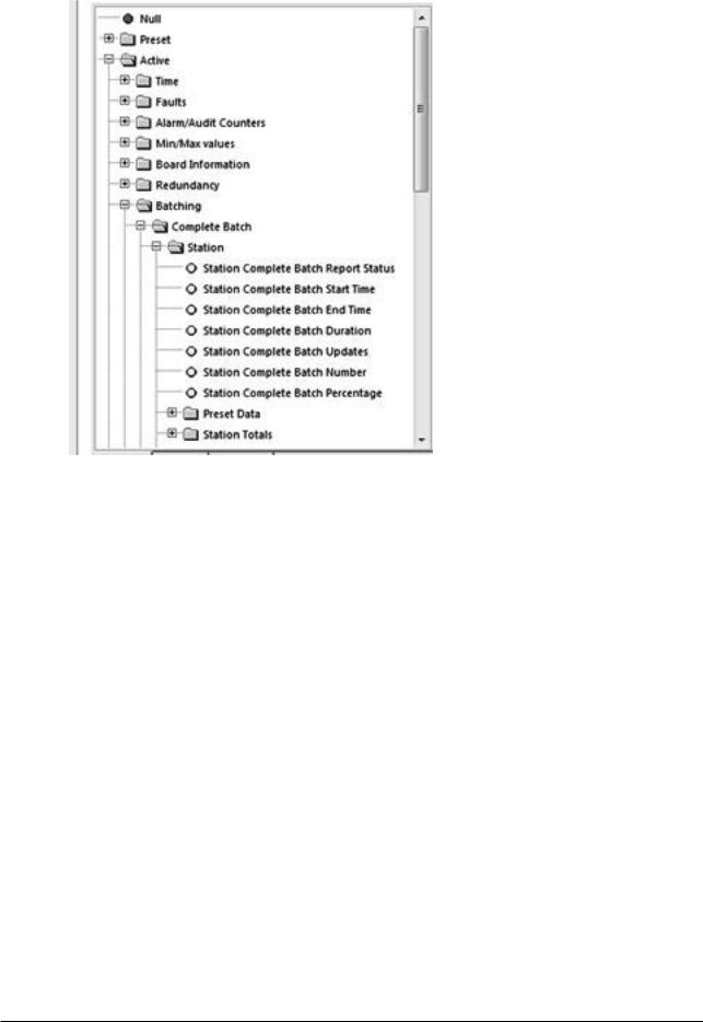
2..4 ID Data Tree
When selecting parameters and options in the Configurator software, the user will be presented with a tree structure for instance:
16 |
www.krohne.com |
08/2013 - MA SUMMIT 8800 Vol3 R02 en |
|
GENERAL INFORMATION |
|
SUMMIT 8800 |
02 |
|
|
|
|
Figure 1 Example ID Tree
This is referred to as the ID tree which, depending on its context, includes folders and several parameters:
2..4..1 Type of data
The rest of this chapter will explain the folders available, the type of selection within the folder and any other corresponding data.
Preset Data
Essential to the configuration of the flow computer. Typical data would be keypad values, operating limits, equation selection, calibration data for Turbines and Densitometers and Orifice plates.
This data would be present in a configuration report, and enables you to see what the flow computer is configured to do.
Used for validation and will form the Data Checksum (visible on the System Information Page). E.g., if a data checksum changes, the setup of the flow computer has changed and potentially calculating different results to what is expected.
Typically configured and left alone, only updated after validation e.g. every 6 month / 1 year.
Active Data
These values cover inputs to the flow computer. E.g. from GC, pressure & temperature transmitters, meters etc..
Also Values calculated in the flow computer. E.g. Flow rates, Z, Averages, Density etc..
Local Data
Data that an operator can change locally to perform maintenance tasks. E.g., turn individual transmitters off without generating alarms. Setting Maintenance mode or Proving Mode.
08/2013 - MA SUMMIT 8800 Vol3 R02 en |
www.krohne.com |
17 |

|
GENERAL INFORMATION |
|
02 |
SUMMIT 8800 |
|
|
|
|
Totals
Totals for the streams and station.
Contents of this folder are stored in the non-volatile RAM and are protected using the battery.
Custom
User defined variables.
Allows calculations, made in a LUA script, to be used in a configuration.
For details, see volume 3.
2..4..2 Colour codes
With each parameter and option, there are corresponding coloured dots that represent the access and status of the particular selection.
General ID tree
|
Red Dot |
Data is Read/Write and can be changed over Modbus. |
|
|
|
|
Yellow Dot |
Data is Read-Only and cannot be changed over Modbus |
|
|
|
Please note that it might be possible to change the values via the screen
90% of the data will be Read Only, but items such as Serial Gas Compositions, Time/Date, MF are commonly written over Modbus.
NOTE: Although the ID may be read/write, the security setting determines whether the ID indeed can be written.
Alarm Tree
The alarm tree is built of all the registers that hold alarm data. Alarm registers are 32-bit integers, where each bit represents a different alarm.
|
Red Dot |
Represents an accountable alarm visible on the alarm list. |
|
|
|
|
Dark Blue Dot |
Represents a non-accountable alarm visible on the alarm list. |
|
|
|
|
Orange Dot |
Represents a warning visible on the alarm list. |
|
|
|
|
Light Blue Dot |
Represents a status alarm, not visible on the alarm list. |
|
|
|
|
Black/Grey Dot |
Represents a hardor software fault alarm visible on the alarm list. |
|
|
|
An example of typical usage would be the General Alarm Register. This is a 32 bit register that indicates up to 32 different alarms in the flow computer. This will contain Status Alarms, for example, 1 bit will indicate if there is a Pressure alarm or not. If the Pressure Status bit is set the user will know that there is a problem with the Pressure.
This should be sufficient information, however if it is not satisfactory, the user can look at the Pressure alarm, this contains 32 different alarms relating to the Pressure measurement, these would be Red Dots as they each can create an entry in the alarm list. By reading this register the user can view exactly what is wrong with the Pressure measurement.
The Light Blue Dots are generally an OR of several other dots. By reading the General register you can quickly see if the unit is healthy, more information can be provided by reading several more registers associated with that parameter.
18 |
www.krohne.com |
08/2013 - MA SUMMIT 8800 Vol3 R02 en |
|
GENERAL INFORMATION |
|
SUMMIT 8800 |
02 |
|
|
|
|
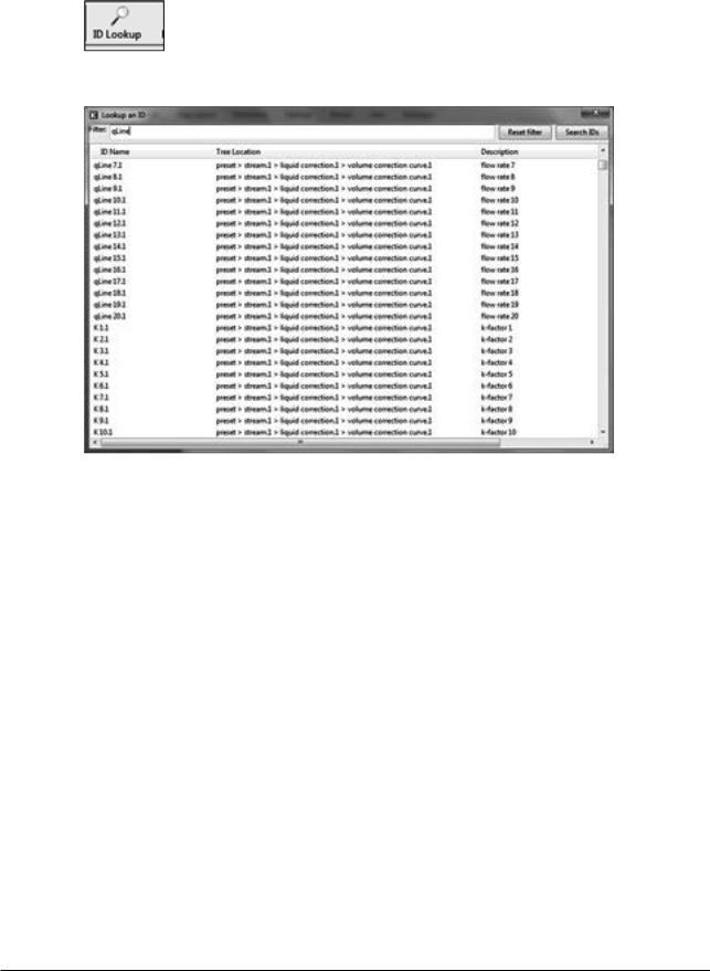
2..4..3 ID Lookup
When pressing the ID lookup button on top of the screen, a lookup table will be generated:
Figure 2 ID lookup
As there are very many ID’s, it is possible to filter for a required ID.
2..5 Specific Requirements for Meters and Volume Convertors
2..5..1 Numbering formats
The number formats used internally in the unit are generally IEEE Double Precision floating point numbers of 64 bit resolution.
It is accepted that such numbers will yield a resolution of better than 14 significant digits.
In the case of Totalisation of Gas, Volumes, Mass and Energy such numbers are always shown to a resolution of 8 digits before the decimal point and 4 after, i.e. 12 significant digits.
Depending upon the required significance of the lowest digit, these values can be scaled by a further multiplier.
2..5..2 Alarms
Each of the various modules that comprise the total operating software, are continuously monitored for correct operation. Depending upon the configuration, the flow computer will complete its allotted tasks within the configured cycle time, 250mS, 500mS or 1 second. Failure to complete the tasks within the time will force the module to complete, and where appropriate, a substitute value issued together with an alarm indication.
For example, if a Calculation fails to complete correctly then a result of 1 or similar will be returned, which allows the unit to continue functioning whilst an accountable alarm is raised, indicating an internal problem.
08/2013 - MA SUMMIT 8800 Vol3 R02 en |
www.krohne.com |
19 |
|
GENERAL INFORMATION |
|
02 |
SUMMIT 8800 |
|
|
|
|
2..5..2..1 Accountable alarm |
|
|
When the value of any measurement item or communication to an associated device that is providing measurement item to the SUMMIT 8800 goes out of range, the flow computer will issue an Accountable Alarm.
When any calculation module or other item that in some way affects the ultimate calculation result goes outside its operating band, i.e. above Pressure Maximum or below Pressure minimum, then the SUMMIT 8800 will issue an Accountable Alarm.
When the SUMMIT 8800 issues an Accountable alarm a number of consequences will occur as follows:
Front panel accountable alarm will turn on and Flash.
Nature of accountable alarm will be shown on the top line of the alarm log. Alarm log will wait for user acknowledgement of alarm.
During the period of the alarm, main totalisation will occur on the alarm counters.
2..5..3 Optional consequences
Depending upon the configuration of the SUMMIT 8800 the following optional Consequences will also occur:
An Entry will be made in the Audit Log, with Time and Date of occurrence.
The “Used” value of the Parameter in Alarm will be substituted by an alternative value, either from an alternative measurement source that is in range, or from a pre-set value.
A digital Alarm output will indicate an Alarm condition.
20 |
www.krohne.com |
08/2013 - MA SUMMIT 8800 Vol3 R02 en |
|
CONFIGURATOR SOFTWARE |
|
SUMMIT 8800 |
03 |
|
|
|
|
For initial installation of the software refer to Volume 1 of the handbook. For Hardware and instrumentation, refer to Volume 2 of the handbook
Alter starting the configuration software, the option menu appears:
Figure 3 Configurator option selections
Select Edit Offline, this function allows the user to create or modify a new configuration without actually being connected to the flow computer.
Figure 4 Application firmware version
Select the correct software version. The software must be compliant to the connected Summit 8800 firmware version, details of system information can be found in volume 1. We assume that the version mentioned in append 1 is selected.
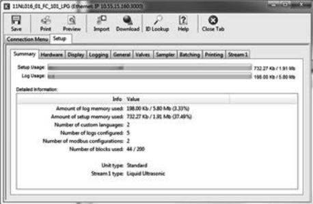
The main configuration page of the Configurator software is displayed and will be the starting point for this manual.
08/2013 - MA SUMMIT 8800 Vol3 R02 en |
www.krohne.com |
21 |
|
CONFIGURATOR SOFTWARE |
|
03 |
SUMMIT 8800 |
|
|
|
|
Figure 5 Main Configurator display
22 |
www.krohne.com |
08/2013 - MA SUMMIT 8800 Vol3 R02 en |
|
DATE & TIME |
|
SUMMIT 8800 |
04 |
|
|
|
|
The Summit has a battery backed real-time clock. The clock can be set in several ways:
-Initially a fixed value via the configuration software
-Initially the time of the computer downloading the configuration software..
-Automatically synchronized via an SNTP server
-Manually via the screen
The format of the time can be changed to fit international needs.
The Summit also knows a contract time as often a buyer and seller have different moment of a day that they like to generate reports, e.g. at 00:00 hours and 06:00 hours. Only required if more than one report time is needed.
4..1 Initial setting of date and time
In the configuration software the initial settings for date and time can be set together with and the display format and the contract time:
Figure 6 Date & time and contract time selection
Set date from |
Select from |
|
|
• Don’t send |
Leave the Summit clock untouched. |
|
|
• Set from PC’s date/time |
Change the Summit clock to the PC date/time when downloading the |
|
software |
• Set from custom settings |
Change the Summit clock to a manual settings when downloading |
|
|
Date/ time |
Date and time for manual setting |
|
|
Date / time format |
Select the format needed |
|
|
Contract time |
Select the time as per customer needs. |
|
|
|
|
08/2013 - MA SUMMIT 8800 Vol3 R02 en |
www.krohne.com |
23 |
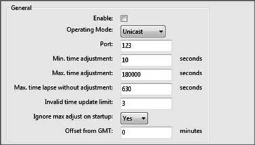
|
DATE & TIME |
|
04 |
SUMMIT 8800 |
|
|
|
|
4..2 SNTP Time Synchronisation
The SNTP or Simple Network Time Protocol is available to synchronise the internal clock with a network time server. While the internal clock’s accuracy is limited to about 3 ppm/°C, these time servers are based on atomic clocks to guarantee the best accuracy. This function also ensures that all flow computers in a network are using the same time.
The flow computer works with time servers using version 3 or 4 of the SNTP protocol, either Unicast or Broadcast:
•Unicast is where the flow computer will request the time from a specified time server.
•Broadcast is when the flow computer waits for a broadcast packet from a time server, and then confirms the results by using a unicast request.
The SNTP can be setup in the hardware section under the Ethernet SNTP:
Figure 7 SNTP Date & time general settings
Enable |
Click the box to enable SNTP |
|
|
Operating mode |
Set the mode as unicast or multicast |
|
|
Port |
The port used for SNTP standard specifies that this should be 123. |
|
|
Min time adjustment |
Minimum amount of time the flow computer clock can be adjusted |
|
|
Max time adjustment |
Maximum amount of time the flow computer clock can be adjusted |
|
|
Max time without adjustment |
Maximum number of seconds that the flow computer can be expected |
|
to operate without receiving a new time from the time server. If this time |
|
is exceeded without receiving a new time then the flow computer will |
|
give a warning. |
Invalid time update limit |
Maximum number of bad updates that can be received before a warning |
|
is given. |
|
|
Ignore max adjust on startup |
Indicates if the maximum time adjustment value should be ignored for |
|
the first valid time received by the flow computer after power up. |
|
|
Offset from GMT |
The time zone of the local time as an offset from the atom clock +/- |
|
GMT minutes |
|
|
24 |
www.krohne.com |
08/2013 - MA SUMMIT 8800 Vol3 R02 en |
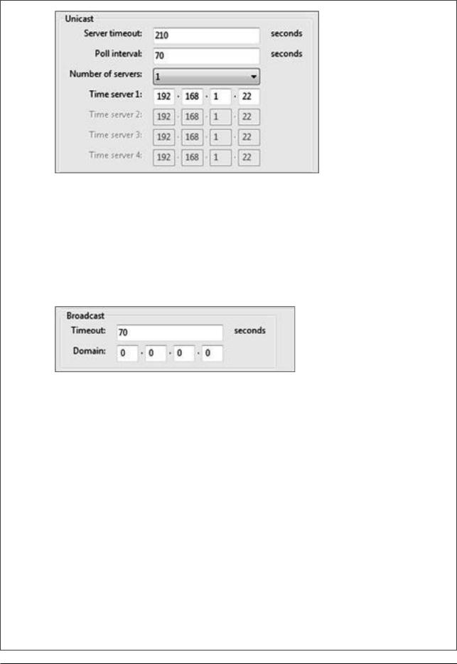
|
|
|
DATE & TIME |
|
SUMMIT 8800 |
04 |
|||
|
|
|
|
|
|
|
|
|
|
|
|
|
|
|
Figure 8 SNTP Date & time unicast settings
Server timeout |
The timeout that applies to each server, after which the next available server in |
|
|
the list is tried. It is recommended that this value is a factor of the maximum |
|
|
time without adjustment. |
|
Poll interval |
Frequency of the flow computer polling the time server. It is recommended that |
|
|
this value is not divisible by 60. |
|
|
|
|
Number of servers |
The number of time servers the flow computer can connect to. |
|
|
|
|
Time server |
IP address of each server. |
|
|
|
|
|
|
|
|
|
|
Figure 9 SNTP Date & time broadcast settings
Broadcast timeout |
The flow computer the waits for a broadcast before giving an alarm. It is |
|
recommended that this value is a factor of the maximum time without |
|
adjustment. |
Broadcast domain. |
IP address on the client subnet for the client operating in broadcast mode to |
|
listen for time updates from broadcast servers. |
4..3 Manually change date and time
To be able to set the date and time manually, a display item has to be created under “Security” with the time in it. (see also next chapter).
08/2013 - MA SUMMIT 8800 Vol3 R02 en |
www.krohne.com |
25 |

|
DATE & TIME |
|
04 |
SUMMIT 8800 |
|
|
|
|
Figure 10 Manual Date & time settings
If the operator then goes into Edit mode, he can change the time as follows:
Figure 11 Manual Date & time adjustment
26 |
www.krohne.com |
08/2013 - MA SUMMIT 8800 Vol3 R02 en |
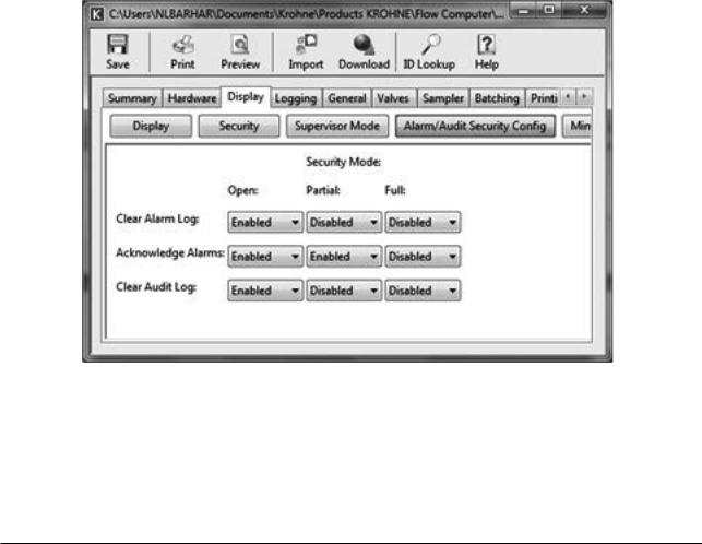
|
DATA LOGGING |
|
SUMMIT 8800 |
05 |
|
|
|
|
To store historical data is one of the major functions of a flow computer. The Summit 8800 is has 3 types of log’s:
Alarm log |
Storage of current and historical alarms. |
|
|
Audit trail log |
Storage of any change made to the unit that has metrological significance. |
|
|
Data log |
Storage of user defined data, either periodically or event diven. |
|
|
The first two are system logs and cannot be changed, however an audit log can be extended with user defined data.
5..1 Alarm and audit log security
It is possible to define what to do with alarm acknowledgment and clearing alarm and audit logs depending on the 4 hardware security switches on the back of the Summit. Two of them determine the security mode of the Summit:
Open |
Any changes can be made (using user passwords) and applications can be loaded. |
|
|
Partial |
Changes can be made except calibration data. No new application can be loaded. |
|
|
Full |
No changes in parameters, values or any other data is not possible. |
|
|
The different security mode also effects the alarm/ audit clearing and acknowledgment and can be set under “display, alarm/audit security configuration“
Figure 12 Display security window
Clear Alarm Log |
Determines if the alarm log may be cleared in open/ partial/ full mode. |
|
|
Acknowledge Alarms |
Determines if the alarms may be acknowledged in open/ partial/ full mode. |
|
|
Clear Audit Log |
Determines if the audit log may be cleared in open/ partial/ full mode. |
|
|
08/2013 - MA SUMMIT 8800 Vol3 R02 en |
www.krohne.com |
27 |
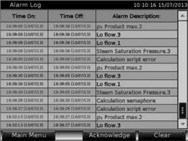
|
DATA LOGGING |
|
05 |
SUMMIT 8800 |
|
|
|
|
5..2 Alarm log
Every time an alarm or warning occurs, it will be stored in the alarm log. The log contains a maximum of 200 entries consisting of time and date when the alarm occurred and vanished plus a description of the alarm or warning.
Figure 13 Alarm log
As the alarm log is a system functions, it does not need any configuration, exept for the alarm acknowledge and clear, which is depending on the security configuration (see previous chapter)
All alarm information stored in the Summit’s internal data flash memory. Each record contains a CRC 32 check which is generated when the log record is created and checked for validity each time data is read from the Unit.
5..3 Audit trail log
Any change made in the Summit which influences the flow measurement in any way is stored in an audit trail to be able to track back what went wrong and possibly recalculate the results.This log contains a maximum of 200 kbyte of internal memory, typically good at least 2000 entries.
Each entry consists of time and date when the event occurred, the operator name, the description of the event and the value before and after change:
28 |
www.krohne.com |
08/2013 - MA SUMMIT 8800 Vol3 R02 en |
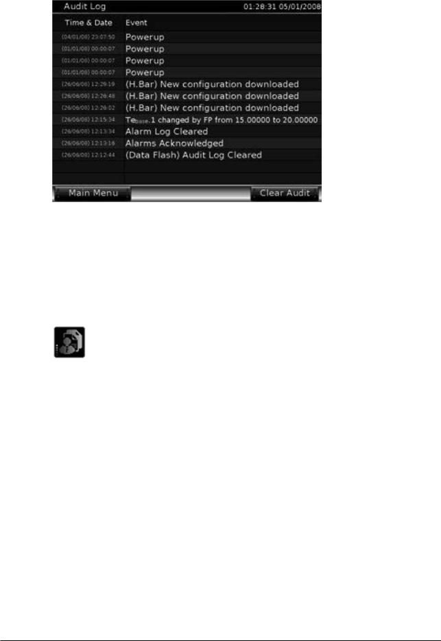
|
DATA LOGGING |
|
SUMMIT 8800 |
05 |
|
|
|
|
Figure 14 Audit trail log
Each record contains a CRC 32 check which is generated when the log record is created and checked for validity each time data is read from the unit.
As the audit trail log is a system functions, it does not need any configuration. However, configuration of the audit acknowledge, which is depending on the security configuration, is possible (see chapter Alarm and audit log security).
5..3..1 Audit log extension
For diagnostic purposes, the user can extend the audit trail with alarms and with up to 10 additional data items per event. These data will be stored on an external SD card only. Configuration can be done under “general” :
08/2013 - MA SUMMIT 8800 Vol3 R02 en |
www.krohne.com |
29 |
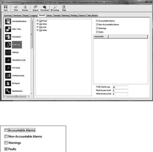
|
DATA LOGGING |
|
05 |
SUMMIT 8800 |
|
|
|
|
Figure 15 Audit log extension
The user can select which alarm types are to be included in the audit log:
Figure 16 Audit log select alarms
Accountable alarms |
Alarms (min or max exceeded) which influence the flow measurements |
|
|
Non-accountable alarms |
Alarms which do not influence the flow measurements |
|
|
Warnings |
Warnings (hi or low exceeded) which do not influence the flow |
|
measurements |
|
|
Faults |
Hardware faults, such as wrong hardware cards inserted for this |
|
application |
Select which additional data is to be recorded for each audit event, often these are the flow totals at time of event:
30 |
www.krohne.com |
08/2013 - MA SUMMIT 8800 Vol3 R02 en |
 Loading...