


 OPTISWIRL 4200 Quick Start
Vortex flowmeter
Electronic revision: ER 1.0.5_
© KROHNE 03/2016 - 4003931402 - QS OPTISWIRL 4200 R02 en

|
CONTENTS |
OPTISWIRL 4200 |
|
|
|
||
|
|
|
|
1 |
Safety instructions |
3 |
|
|
|
|
|
2 |
Installation |
4 |
|
|
|
|
|
|
2.1 |
Intended use ..................................................................................................................... |
4 |
|
2.2 |
Scope of delivery............................................................................................................... |
6 |
|
2.3 |
Storage ............................................................................................................................. |
6 |
|
2.4 |
Transport .......................................................................................................................... |
7 |
|
2.5 |
Installation conditions ...................................................................................................... |
8 |
2.5.1 Prohibited installation when measuring liquids .................................................................... |
9 |
|
2.5.2 Prohibited installation when measuring steam and gases.................................................. |
10 |
|
2.5.3 Pipelines with control valve.................................................................................................. |
10 |
|
2.5.4 Preferred mounting position ................................................................................................ |
11 |
|
2.6 |
Minimum inlet sections .................................................................................................. |
12 |
2.7 |
Minimum outlet sections................................................................................................ |
13 |
2.8 |
Flow straightener ........................................................................................................... |
13 |
2.9 |
Installation...................................................................................................................... |
14 |
2.9.1 General installation notes..................................................................................................... |
14 |
|
2.9.2 Installing devices in sandwich design .................................................................................. |
15 |
|
2.9.3 Installing devices in flange design ....................................................................................... |
16 |
|
2.9.4 Mounting the field housing, remote version ........................................................................ |
17 |
|
2.10 Heat insulation.............................................................................................................. |
18 |
|
2.11 Turning the connection housing................................................................................... |
19 |
|
2.12 Turning the display ....................................................................................................... |
20 |
|
3 Electrical connections |
21 |
|
|
|
|
3.1 |
Safety instructions.......................................................................................................... |
21 |
3.2 |
Connecting the signal converter .................................................................................... |
22 |
3.3 |
Electrical connections .................................................................................................... |
23 |
3.3.1 Power supply......................................................................................................................... |
23 |
|
3.3.2 Current output ...................................................................................................................... |
23 |
|
3.3.3 Current input......................................................................................................................... |
24 |
|
3.3.4 Binary output......................................................................................................................... |
24 |
|
3.3.5 Limit switch output ............................................................................................................... |
25 |
|
3.3.6 Pulse output / Frequency output .......................................................................................... |
27 |
|
3.3.7 Status output......................................................................................................................... |
28 |
|
3.4 |
Connection of remote version ........................................................................................ |
28 |
3.5 |
Grounding connections................................................................................................... |
30 |
3.6 |
Ingress protection .......................................................................................................... |
31 |
2 |
www.krohne.com |
03/2016 - 4003931402 - QS OPTISWIRL 4200 R02 en |

OPTISWIRL 4200
SAFETY INSTRUCTIONS 1
Warnings and symbols used
DANGER!
This information refers to the immediate danger when working with electricity.
DANGER!
These warnings must be observed without fail. Even partial disregard of this warning can lead to serious health problems and even death. There is also the risk of seriously damaging the device or parts of the operator's plant.
WARNING!
Disregarding this safety warning, even if only in part, poses the risk of serious health problems. There is also the risk of damaging the device or parts of the operator's plant.
CAUTION!
Disregarding these instructions can result in damage to the device or to parts of the operator's plant.
INFORMATION!
These instructions contain important information for the handling of the device.
HANDLING
•This symbol designates all instructions for actions to be carried out by the operator in the specified sequence.
iRESULT
This symbol refers to all important consequences of the previous actions.
Safety instructions for the operator
CAUTION!
Installation, assembly, start-up and maintenance may only be performed by appropriately trained personnel. The regional occupational health and safety directives must always be observed.
LEGAL NOTICE!
The responsibility as to the suitability and intended use of this device rests solely with the user. The supplier assumes no responsibility in the event of improper use by the customer. Improper installation and operation may lead to loss of warranty. In addition, the "Terms and Conditions of Sale" apply which form the basis of the purchase contract.
INFORMATION!
•Further information can be found on the supplied CD-ROM in the manual, on the data sheet, in special manuals, certificates and on the manufacturer's website.
•If you need to return the device to the manufacturer or supplier, please fill out the form contained on the CD-ROM and send it with the device. Unfortunately, the manufacturer cannot repair or inspect the device without the completed form.
03/2016 - 4003931402 - QS OPTISWIRL 4200 R02 en |
www.krohne.com |
3 |

2 INSTALLATION |
OPTISWIRL 4200 |
|
2.1 Intended use
CAUTION!
Responsibility for the use of the measuring devices with regard to suitability, intended use and corrosion resistance of the used materials against the measured fluid lies solely with the operator.
INFORMATION!
This device is a Group 1, Class A device as specified within CISPR11:2009. It is intended for use in industrial environment. There may be potential difficulties in ensuring electromagnetic compatibility in other environments, due to conducted as well as radiated disturbances.
INFORMATION!
The manufacturer is not liable for any damage resulting from improper use or use for other than the intended purpose.
The vortex flowmeters are used for flow measurement of gases, vapours and liquids.
The devices are particularly suitable for the measurement of:
•Clean liquids with low viscosity (< 10 cP)
•Hydrocarbons with low viscosity (< 10 cP)
•Water
•Chemicals with low corrosiveness
•Saturated steam
•Superheated steam, including CIP and SIP applications in the food industry
•The flow sensors are made from stainless steel 316 L (1.4404) or Hastelloy® C22.
•In your project planning, please observe the data given in the corrosion tables.
•The pressure-bearing parts have been designed and rated for stationary operation taking into account the maximum pressure and temperature.
•Observe the data indicated on the nameplate for PS, TS and PT (PED 97/23/EC).
•External forces and moments, caused e.g. by pipe stresses, have not been taken into account.
Primarily, volumetric flow and temperature are measured, with pressure measurement as an option. From these parameters the measuring device calculates the mass flow or standard volumetric flow using pre-programmed density data and then exports the measured values via various communication interfaces.
4 |
www.krohne.com |
03/2016 - 4003931402 - QS OPTISWIRL 4200 R02 en |

|
|
INSTALLATION 2 |
|
OPTISWIRL 4200 |
|
|
|
|
The devices are rated for the following flow velocities:
Liquids: |
|
Vmin: 0.25 m/s |
0.8 ft/s |
|
1 |
DN15...DN300 |
|
|
|
|
|
|
|
|
|
|
|
|
|
Vmax: 10 m/s |
32 ft/s |
|
2 |
|
|
|
|
|
|
Gases and |
DN15 |
Vmin: 3 m/s |
10 ft/s |
|
1 |
steam: |
|
|
|
|
|
|
|
|
|
|
|
|
|
Vmax: 45 m/s |
147 ft/s |
|
2 |
|
|
|
|
|
|
|
DN15C |
Vmin: 3 m/s |
10 ft/s |
|
1 |
|
|
|
|
|
|
|
|
Vmax: 55 m/s |
180 ft/s |
|
2 |
|
|
|
|
|
|
|
DN25 |
Vmin: 2 m/s |
6.6 ft/s |
|
1 |
|
|
|
|
|
|
|
|
Vmax: 70 m/s |
229 ft/s |
|
2 |
|
|
|
|
|
|
|
DN25C |
Vmin: 2 m/s |
6.6 ft/s |
|
1 |
|
|
|
|
|
|
|
|
Vmax: 80 m/s |
262 ft/s |
|
2 |
|
|
|
|
|
|
|
DN40... |
Vmin: 2 m/s |
6.6 ft/s |
|
1 |
|
DN300 |
|
|
|
|
|
|
|
|
|
|
|
|
Vmax: 80 m/s |
262 ft/s |
|
2 |
|
|
|
|
|
|
1Use the larger value, according to the amount.
2Use the smaller value, according to the amount.
INFORMATION!
DN15C and DN25C have a robust flow sensor (signal pick-up) for harsh measuring conditions and higher maximum velocity compared to the standard version.
03/2016 - 4003931402 - QS OPTISWIRL 4200 R02 en |
www.krohne.com |
5 |

2 INSTALLATION |
OPTISWIRL 4200 |
|
2.2 Scope of delivery
INFORMATION!
Inspect the packaging carefully for damages or signs of rough handling. Report damage to the carrier and to the local office of the manufacturer.
INFORMATION!
Do a check of the packing list to make sure that you have all the elements given in the order.
INFORMATION!
Look at the device nameplate to ensure that the device is delivered according to your order. Check for the correct supply voltage printed on the nameplate.
Figure 2-1: Scope of delivery
1Measuring device in ordered version
2Product documentation
3Certificates, calibration report and parameter data sheet
4CD with complete documentation
5Bar magnet
6Centering rings (only for sandwich devices)
7Handle to pull off the display
8Key for opening the front and rear cover
2.3Storage
•Store the device in a dry, dust-free location.
•Avoid extended direct exposure to the sun.
•Store the device in the original packaging.
•The permissible storage temperature for standard devices is -40...+85°C / -40...+185°F.
6 |
www.krohne.com |
03/2016 - 4003931402 - QS OPTISWIRL 4200 R02 en |

|
|
INSTALLATION 2 |
|
OPTISWIRL 4200 |
|
|
|
|
2.4Transport
•Use lifting straps wrapped around both process connections for transport.
•Do not lift measuring devices by the signal converter housing for transport.
•Never lift the measuring device by the pressure sensor.
•Do not use lifting chains as they may damage the housing.
Figure 2-2: Transport instructions
CAUTION!
Non-secured devices can pose risk of injury. The centre of mass of the device is often higher than the point at which the lifting straps are attached.
Prevent the measuring device from sliding or rotating accidentally.
03/2016 - 4003931402 - QS OPTISWIRL 4200 R02 en |
www.krohne.com |
7 |

2 INSTALLATION |
OPTISWIRL 4200 |
|
2.5 Installation conditions
INFORMATION!
For accurate volumetric flow measurement the measuring device needs a completely filled pipe and a fully developed flow profile.
CAUTION!
Any vibration will distort the measuring result. That is why any vibrations in the pipeline must be prevented through suitable measures.
CAUTION!
Procedures to carry out before installing the device:
•Nominal diameter of connection pipe flange = nominal flange diameter of pipe!
•Use flanges with smooth holes, e.g. welding neck flanges.
•Align carefully the holes of the connecting flange and the flowmeter flange.
•Check the compatibility of the gasket material with the process product.
•Make sure that the gaskets are arranged concentrically. The flange gaskets must not project into the pipe cross-section.
•The flanges have to be concentric.
•There must not be any pipe bends, valves, flaps or other internals in the immediate inlet run.
•Devices in sandwich version may only be installed using centering rings.
•Never install the device directly behind piston compressors or rotary piston meters.
•Do not lay signal cables directly next to cables for the power supply.
INFORMATION!
If there is a risk of water hammers in steam networks, appropriate condensate separators must be installed. Suitable measures must be taken to avoid water cavitation if it is a possible risk.
Sunshades
Figure 2-3: Installation recommendations
1Horizontal mounting
2Vertical mounting
The meter MUST be protected from strong sunlight.
A sunshade is available from the manufacturer as an option.
8 |
www.krohne.com |
03/2016 - 4003931402 - QS OPTISWIRL 4200 R02 en |

|
|
INSTALLATION 2 |
|
OPTISWIRL 4200 |
|
|
|
|
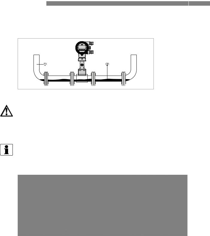
2.5.1 Prohibited installation when measuring liquids
Figure 2-4: Upper pipe bend
CAUTION!
Prohibited: Installing the device in an upper pipe bend 1, because there is a risk of gas bubbles 2 forming. Gas bubbles can lead to pressure surges and inaccurate measurement.
Figure 2-5: Downstream pipe and outlet
CAUTION!
Installing the device in a downstream pipe 3 or upstream pipe of an outlet 4. There is the risk of partially filled pipes leading to inaccurate measurements.
03/2016 - 4003931402 - QS OPTISWIRL 4200 R02 en |
www.krohne.com |
9 |
2 INSTALLATION |
OPTISWIRL 4200 |
|
2.5.2 Prohibited installation when measuring steam and gases
1Lower pipe bends
2Condensate
DANGER!
Prohibited: Installing the device in a lower pipe bend 1, because there is a risk of condensate forming 2.
Condensate can lead to cavitation and inaccurate measurement. Under certain circumstances the device can be destroyed and the measured product can leak.
2.5.3 Pipelines with control valve
INFORMATION!
To ensure smooth and correct measurement, the manufacturer recommends not installing the measuring device downstream from a control valve. This would run the risk of vortex formation, which would distort the measuring result.
Figure 2-6: Pipeline with control valve
1Recommended: installing the device before the control valve at a distance of ≥ 5 DN
2Not recommended: Installing the flowmeter directly downstream of control valves, due to vortex formation.
10 |
www.krohne.com |
03/2016 - 4003931402 - QS OPTISWIRL 4200 R02 en |
 Loading...