


 OPTIMASS 6000 Handbook
Sensor for mass flow
The documentation is only complete when used in combination with the relevant documentation for the signal converter.
© KROHNE 07/2014 - 4001894003 - MA OPTIMASS 6000 R03 en
: IMPRINT :::::::::::::::::::::::::::::::::::::::
All rights reserved. It is prohibited to reproduce this documentation, or any part thereof, without the prior written authorisation of KROHNE Messtechnik GmbH.
Subject to change without notice.
Copyright 2014 by
KROHNE Messtechnik GmbH - Ludwig-Krohne-Str. 5 - 47058 Duisburg (Germany)
2 |
www.krohne.com |
07/2014 - 4001894003 - MA OPTIMASS 6000 R03 en |

|
|
|
CONTENTS |
|
|
||
|
OPTIMASS 6000 |
|
|||||
|
|
|
|
|
|
||
1 |
Safety instructions |
5 |
|
||||
|
|
|
|
|
|
|
|
|
|
|
1.1 |
Intended use ..................................................................................................................... |
5 |
|
|
|
|
|
1.2 |
CE certification ................................................................................................................. |
5 |
|
|
|
|
|
1.3 |
Associated documents ..................................................................................................... |
5 |
|
|
|
|
|
1.4 |
Insulation case.................................................................................................................. |
5 |
|
|
|
|
|
1.5 |
Pressure Equipment Directive (PED)............................................................................... |
6 |
|
|
|
|
|
1.6 |
Dirty gas............................................................................................................................ |
7 |
|
|
|
|
|
1.7 |
Safety instructions from the manufacturer ..................................................................... |
7 |
|
|
|
|
|
1.7.1 Copyright and data protection ................................................................................................ |
7 |
|
||
|
|
|
1.7.2 Disclaimer ............................................................................................................................... |
7 |
|
||
|
|
|
1.7.3 Product liability and warranty ................................................................................................ |
8 |
|
||
|
|
|
1.7.4 Information concerning the documentation........................................................................... |
8 |
|
||
|
|
|
1.7.5 Warnings and symbols used................................................................................................... |
9 |
|
||
|
|
|
1.8 |
Safety instructions for the operator................................................................................. |
9 |
|
|
|
|
2 Device description |
10 |
|
|||
|
|
|
|
|
|
||
|
|
|
2.1 |
Scope of delivery............................................................................................................. |
10 |
||
|
|
|
2.1.1 Meters with hygienic connections ........................................................................................ |
11 |
|
||
|
|
|
2.2 |
Nameplates .................................................................................................................... |
11 |
||
|
|
|
2.3 |
Dual Seal........................................................................................................................ |
11 |
||
|
|
|
2.4 |
Temperature differential and thermal shock ................................................................ |
12 |
||
3 |
Installation |
14 |
|
||||
|
|
|
|
|
|
|
|
|
|
|
3.1 |
General notes on installation ......................................................................................... |
14 |
|
|
|
|
|
3.2 |
Storage ........................................................................................................................... |
14 |
||
|
|
|
3.3 |
Handling.......................................................................................................................... |
15 |
||
|
|
|
3.4 |
Installation conditions .................................................................................................... |
16 |
||
|
|
|
3.4.1 Supporting the meter............................................................................................................ |
16 |
|
||
|
|
|
3.4.2 Mounting the meter .............................................................................................................. |
17 |
|
||
|
|
|
3.4.3 Gas / liquid build up .............................................................................................................. |
18 |
|
||
|
|
|
3.4.4 Side mounting ....................................................................................................................... |
18 |
|
||
|
|
|
3.4.5 Cross talk .............................................................................................................................. |
19 |
|
||
|
|
|
3.4.6 Flange connections............................................................................................................... |
19 |
|
||
|
|
|
3.4.7 Maximum pipework forces (end loadings) ........................................................................... |
20 |
|||
|
|
|
3.4.8 Pipework reducers................................................................................................................ |
20 |
|
||
|
|
|
3.4.9 Flexible connections ............................................................................................................. |
21 |
|
||
|
|
|
3.4.10 Hygienic installations.......................................................................................................... |
21 |
|
||
|
|
|
3.4.11 Heating and insulation ........................................................................................................ |
22 |
|
||
|
|
|
3.4.12 Purge ports ......................................................................................................................... |
23 |
|
||
|
|
|
3.4.13 Burst discs .......................................................................................................................... |
23 |
|
||
|
|
|
3.4.14 Zero calibration................................................................................................................... |
24 |
|
||
|
|
|
3.4.15 Sunshades........................................................................................................................... |
24 |
|
||
07/2014 - 4001894003 - MA OPTIMASS 6000 R03 en |
www.krohne.com |
3 |

|
CONTENTS |
|
|
|
OPTIMASS 6000 |
|
|
|
|
|
|
4 Electrical connections |
25 |
|
4.1 |
Safety instructions.......................................................................................................... |
25 |
4.2 |
Electrical and I/O connections ....................................................................................... |
25 |
5 Service |
26 |
|
5.1 |
Spare parts availability................................................................................................... |
26 |
5.2 |
Availability of services .................................................................................................... |
26 |
5.3 |
Returning the device to the manufacturer..................................................................... |
26 |
5.3.1 General information.............................................................................................................. |
26 |
|
5.3.2 Form (for copying) to accompany a returned device............................................................ |
27 |
|
5.4 |
Disposal .......................................................................................................................... |
27 |
6 Technical data |
28 |
|
6.1 |
Measuring principle (twin tube) ..................................................................................... |
28 |
6.2 |
Technical data................................................................................................................. |
30 |
6.3 |
Measuring accuracy ....................................................................................................... |
37 |
6.4 |
Guidelines for maximum operating pressure................................................................ |
37 |
6.5 |
Dimensions and weights ................................................................................................ |
42 |
6.5.1 Flanged versions................................................................................................................... |
42 |
|
6.5.2 NAMUR dimensions .............................................................................................................. |
53 |
|
6.5.3 Hygienic versions .................................................................................................................. |
54 |
|
6.5.4 Heating jacket version .......................................................................................................... |
57 |
|
6.5.5 Purge port option .................................................................................................................. |
58 |
|
6.5.6 Burst discs ............................................................................................................................ |
58 |
|
6.5.7 Burst disc option ................................................................................................................... |
59 |
|
4 |
www.krohne.com |
07/2014 - 4001894003 - MA OPTIMASS 6000 R03 en |

|
|
SAFETY INSTRUCTIONS 1 |
|
OPTIMASS 6000 |
|
|
|
|
1.1 Intended use
This mass flowmeter is designed for the direct measurement of mass flow rate, product density and product temperature. Indirectly, it also enables the measurement of parameters like total mass, concentration of dissolved substances and the volume flow. For use in hazardous areas, special codes and regulations are also applicable and these are specified in a separate documentation.
1.2 CE certification
CE marking
This device conforms with the following EC directives:
•EMC Directive 2004/108/EC
•ATEX Directive 94/9/EC
•Low Voltage Directive 2006/95/EC
•Pressure Equipment Directive 97/23/EC
The manufacturer declares conformity and the device carries the CE mark.
1.3 Associated documents
This handbook should be read in conjunction with relevant documents in relation to:
•hazardous areas
•communications
•concentration
•corrosion
1.4Insulation case
On meters fitted with an insulation case, the case will be filled with one of the following materials:
Cryogenic meters (-200°C...+40°C / -364°F...+104°F)
Block grade EPS 1112A (Polystyrene) containing flame retardant additive (FRA)
Standard meters (-70°C...+230°C / -94°F...+446°F)
Glass mineral wool
07/2014 - 4001894003 - MA OPTIMASS 6000 R03 en |
www.krohne.com |
5 |
1 SAFETY INSTRUCTIONS |
|
|
OPTIMASS 6000 |
|
|
|
|
|
High temperature meters (-50°C...+400°C / -58°F...+752°F)
Silicon dioxide based mineral wool
Do not open the insulation case. Some, or all, of the above materials can cause:
•skin irritation
•throat and lung irritation
•eye irritation
Install the meter so that water cannot get into the insulation case. Water will damage the insulation material and reduce performance.
1.5 Pressure Equipment Directive (PED)
LEGAL NOTICE!
The Pressure Equipment Directive places legal requirements on both the manufacturer and the end user. Please read this section carefully!
To ensure the PED integrity of the meter, you MUST check that the serial numbers on the converter nameplate and the sensor nameplate are the same.
To comply with the requirements of the Pressure Equipment Directive (PED) the manufacturer provides all the relevant technical data in the technical data section of this handbook. Secondary pressure containment is NOT supplied on this meter.
Tube failure
Where the meter is being used to measure high pressure gasses and / or gasses kept as liquids by high pressure and / or where there is a risk of tube failure because of the use of corrosive or erosive fluids, frequent pressure and / or thermal cycling, seismic or other shock loading, the burst disc option MUST be purchased. For more information, please contact your nearest representative.
DANGER!
If it is suspected that the primary measuring tube has failed, de-pressurise the meter and remove it from service as soon as it is safe to do so.
6 |
www.krohne.com |
07/2014 - 4001894003 - MA OPTIMASS 6000 R03 en |
|
|
SAFETY INSTRUCTIONS 1 |
|
OPTIMASS 6000 |
|
|
|
|
1.6 Dirty gas
Dirty gas is gas that carries sand or other solid particles. Dirty gas causes excessive wear to the primary measuring tube that can eventually result in complete tube failure. In some situations tube failure where gas is being measured, can be very dangerous.
DANGER!
If the meter is being used to measure gas and there is a risk that the gas might be dirty, you must fit a filter upstream of the meter to catch solid particles.
1.7 Safety instructions from the manufacturer
1.7.1 Copyright and data protection
The contents of this document have been created with great care. Nevertheless, we provide no guarantee that the contents are correct, complete or up-to-date.
The contents and works in this document are subject to copyright. Contributions from third parties are identified as such. Reproduction, processing, dissemination and any type of use beyond what is permitted under copyright requires written authorisation from the respective author and/or the manufacturer.
The manufacturer tries always to observe the copyrights of others, and to draw on works created in-house or works in the public domain.
The collection of personal data (such as names, street addresses or e-mail addresses) in the manufacturer's documents is always on a voluntary basis whenever possible. Whenever feasible, it is always possible to make use of the offerings and services without providing any personal data.
We draw your attention to the fact that data transmission over the Internet (e.g. when communicating by e-mail) may involve gaps in security. It is not possible to protect such data completely against access by third parties.
We hereby expressly prohibit the use of the contact data published as part of our duty to publish an imprint for the purpose of sending us any advertising or informational materials that we have not expressly requested.
1.7.2 Disclaimer
The manufacturer will not be liable for any damage of any kind by using its product, including, but not limited to direct, indirect or incidental and consequential damages.
This disclaimer does not apply in case the manufacturer has acted on purpose or with gross negligence. In the event any applicable law does not allow such limitations on implied warranties or the exclusion of limitation of certain damages, you may, if such law applies to you, not be subject to some or all of the above disclaimer, exclusions or limitations.
Any product purchased from the manufacturer is warranted in accordance with the relevant product documentation and our Terms and Conditions of Sale.
07/2014 - 4001894003 - MA OPTIMASS 6000 R03 en |
www.krohne.com |
7 |

1 SAFETY INSTRUCTIONS |
|
|
OPTIMASS 6000 |
|
|
|
|
|
The manufacturer reserves the right to alter the content of its documents, including this disclaimer in any way, at any time, for any reason, without prior notification, and will not be liable in any way for possible consequences of such changes.
1.7.3 Product liability and warranty
The operator shall bear responsibility for the suitability of the device for the specific purpose. The manufacturer accepts no liability for the consequences of misuse by the operator. Improper installation and operation of the devices (systems) will cause the warranty to be void. The respective "Standard Terms and Conditions" which form the basis for the sales contract shall also apply.
1.7.4 Information concerning the documentation
To prevent any injury to the user or damage to the device it is essential that you read the information in this document and observe applicable national standards, safety requirements and accident prevention regulations.
If this document is not in your native language and if you have any problems understanding the text, we advise you to contact your local office for assistance. The manufacturer can not accept responsibility for any damage or injury caused by misunderstanding of the information in this document.
This document is provided to help you establish operating conditions, which will permit safe and efficient use of this device. Special considerations and precautions are also described in the document, which appear in the form of underneath icons.
8 |
www.krohne.com |
07/2014 - 4001894003 - MA OPTIMASS 6000 R03 en |

|
|
SAFETY INSTRUCTIONS 1 |
|
OPTIMASS 6000 |
|
|
|
|
1.7.5 Warnings and symbols used
Safety warnings are indicated by the following symbols.
DANGER!
This warning refers to the immediate danger when working with electricity.
DANGER!
This warning refers to the immediate danger of burns caused by heat or hot surfaces.
DANGER!
This warning refers to the immediate danger when using this device in a hazardous atmosphere.
DANGER!
These warnings must be observed without fail. Even partial disregard of this warning can lead to serious health problems and even death. There is also the risk of seriously damaging the device or parts of the operator's plant.
WARNING!
Disregarding this safety warning, even if only in part, poses the risk of serious health problems. There is also the risk of damaging the device or parts of the operator's plant.
CAUTION!
Disregarding these instructions can result in damage to the device or to parts of the operator's plant.
INFORMATION!
These instructions contain important information for the handling of the device.
LEGAL NOTICE!
This note contains information on statutory directives and standards.
• HANDLING
This symbol designates all instructions for actions to be carried out by the operator in the specified sequence.
iRESULT
This symbol refers to all important consequences of the previous actions.
1.8Safety instructions for the operator
WARNING!
In general, devices from the manufacturer may only be installed, commissioned, operated and maintained by properly trained and authorized personnel.
This document is provided to help you establish operating conditions, which will permit safe and efficient use of this device.
07/2014 - 4001894003 - MA OPTIMASS 6000 R03 en |
www.krohne.com |
9 |
2 DEVICE DESCRIPTION |
|
|
OPTIMASS 6000 |
|
|
|
|
|
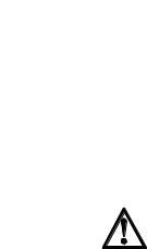
2.1 Scope of delivery
Compact version
1Mass flowmeter.
2Carton.
3Documentation.
42.5 mm and 5 mm hex head tools.
5CD-ROM and calibration certificate.
Remote version
1Mass flowmeter.
2Converter. This will be either: field (as shown), wall or rack.
3Carton.
42.5 mm and 5 mm hex head tools.
5CD-ROM and calibration certificate.
6Documentation.
If any items are missing, please contact the manufacturer.
If your meter has flange connections, the flange specification is stamped on the outer edge of the flange. Check that the specification on the flange is the same as your order.
10 |
www.krohne.com |
07/2014 - 4001894003 - MA OPTIMASS 6000 R03 en |
|
|
DEVICE DESCRIPTION 2 |
|
OPTIMASS 6000 |
|
|
|
|
2.1.1 Meters with hygienic connections
1Fully welded - the O-rings between the meter and the process pipework are not supplied as standard but can be ordered.
2DIN 11864-2 Form A - the O-rings between the Form A and Form B parts of the connection are not supplied as standard but can be ordered.
3The 11864-2 Form B is not supplied as part of this connection but it can be ordered.
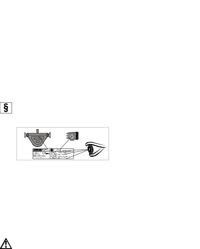
2.2Nameplates
INFORMATION!
Look at the device nameplate to ensure that the device is delivered according to your order. Check for the correct supply voltage printed on the nameplate.
2.3 Dual Seal
To comply with the requirements of ANSI/ISA -12.27.01-2011 “Requirements for process Sealing Between electrical systems and Flammable or Combustible process Fluids” a secondary seal is incorporated into all OPTIMASS / GAS products. If the primary seal fails, the secondary seal will prevent escaping fluid reaching the electronic compartment.
Pressures and / or temperatures are limited by tube, temperature, connection and Ex limits. Check the meter nameplates and relevant documentation for full details. On all meters operating on gas measurement, the casing of the meter is fitted with a burst disc. If the primary seal (tube) fails leakage will occur from the burst disc. Install the meter so that the burst disc is pointing away from personnel.
Liquids (Example model code: OPTIMASS 6000F S50 - LIQUID
Pressure and temperature data:
OPTIMASS 6000 / 6000F / 6400C -200°C...+230°C and 100...10000 kPa (Stainless Steel) OPTIMASS 6000 / 6000F / 6400C -50°C...+230°C and 100...20000 kPa (Hastelloy® / duplex) OPTIMASS 6000 / 6000F - HT -50°C...+400°C and 100...10000 kPa
If the primary seal fails, the casing of the meter will fill with liquid and the meter will stop working. The meter will notify the operator by displaying the status message "Sensor: Sensor signal low" on the converter or PLC display. This is an indication that the primary seal (tube) has failed and the status of the meter should be checked.
As soon as it is safe to do so, de-pressurise the process line and remove the meter. Please contact customer service for servicing or replacement of the meter.
07/2014 - 4001894003 - MA OPTIMASS 6000 R03 en |
www.krohne.com |
11 |

2 DEVICE DESCRIPTION |
|
|
OPTIMASS 6000 |
|
|
|
|
|
INFORMATION!
At high pressures, process fluid may also leak from the meter casing. This is also an indicatioin that the primary seal has failed.
Meter status:
The meter will also display the mesage "Sensor: Sensor signal low" if the measuring tubes are not completely filled with fluid. For example, if the meter is drained or re/filled.
To check the status of the meter, drain and re/fill with fluid and note the converter or PLC display. See the relevant section of the converter handbook for a list of status messages and diagnostics information.
If the meter continues to display the message: "Sensor: Sensor signal low" you MUST assume that the primary seal (tubes) has failed and the appropriate action MUST be taken.
Gases (Example model code: OPTIMASS 6000F S50 - GAS)
Pressure / temperature data:
OPTIMASS 6000 / 6000F / 6400C -200°C...+230°C and 500... 10000 kPa (Stainless Steel)
OPTIMASS 6000 / 6000F / 6400C -50°C...+230°C and 500...20000 kPa (Hastelloy® / duplex)
OPTIMASS 6000F - HT -50°C...+400°C and 500...10000 kPa
Pressures and/or temperatures may be further limited by tube, temperature, connection and Ex limits. Consult the meter nameplate and relevant documentation for full details.
On all meters operating on gas measurement the casing of the meter is fitted with a burst disc. If the primary seal (tube/s) fails leakage will occur from the burst disc. Install the meter so that the burst disc is pointing away from personnel.
Regular maintenance of the burst disc:
Carry out regular maintenance checks on burst discs for leakage and/or blockages. On all OPTIMASS meters, the primary seal is considered to be the measuring tube of the meter. The materials of construction of the measuring tube/s are described within the relevant sections of this handbook and the customer’s product and any other fluid flowing through the tube must be compatible with the material of construction. If failure of the primary seal is suspected then the process line should be de-pressurised and the meter removed as soon as it is safe to do so. Please contact customer service for servicing or replacement of the meter.
2.4 Temperature differential and thermal shock
Temperature differential
The maximum difference between ambient temperature and process (operating) temperatures are:
Meter temperature range |
Maximum temperature differential |
||
|
|
|
|
-200°C... |
+40°C / -328°F... |
+104°F |
210°C / 410°F |
|
|
|
|
-70°C... |
+230°C / -94°F... |
+446°F |
|
|
|
|
|
-50°C... |
+400°C / -58°F... |
+752°F |
380°C / 716°F |
|
|
|
|
12 |
www.krohne.com |
07/2014 - 4001894003 - MA OPTIMASS 6000 R03 en |
|
|
DEVICE DESCRIPTION 2 |
|
OPTIMASS 6000 |
|
|
|
|
Thermal shock
Thermal shock occurs when there is a sudden and extreme change (shift) in process temperature. To prevent thermal shock on this meter, the manufacturer recommends that you avoid a temperature shift greater than 100°C / 212°F, at a maximum of 40% of the nominal flow rate.
These limits will give a minimum calculated life span for the meter of 3500 cycles. Thermal shocking below this temperature will increase the life span of the meter. For more information, please contact your nearest representative.
Maximum temperature rate rise
If the change in temperature (rate rise) is greater than 100°C / 212°F, the temperature rise must be over a period of time. Calculate the time required for the whole temperature rise using the table below.
Meter size |
Temp. rate rise |
Example |
|
||
|
|
|
|
|
|
DN 08... |
50 |
6°C / 10.8°F per minute |
20°C... |
230°C / 68°F... |
446°F = 35 |
|
|
|
minutes |
|
|
|
|
|
|
|
|
|
|
|
20°C... |
400°C / 68°F... |
752°F = 80 |
|
|
|
minutes |
|
|
|
|
|
|
|
|
DN 80... |
100 |
3°C / 5.4°F per minute |
20°C... |
230°C / 68°F... |
446°F = 70 |
|
|
|
minutes |
|
|
|
|
|
|
|
|
|
|
|
20°C... |
400°C / 68°F... |
752°F = 140 |
|
|
|
minutes |
|
|
|
|
|
|
|
|
These limits will provide a minimum calculated life span for the meter of 2000 cycles. Temperature rises below 100°C / 212°F, or temperature rises over a longer period of time, will increase the life span of the meter.
CAUTION!
Operation outside these limits may result in shifts in density and mass flow calibration. Repeated shocking and / or rapid heating, may also result in premature failure of the meter. However, higher thermal shocks and / or an increased number of cycles are possible at lower working pressures. For more information, please contact your nearest representative.
07/2014 - 4001894003 - MA OPTIMASS 6000 R03 en |
www.krohne.com |
13 |

3 INSTALLATION |
|
|
OPTIMASS 6000 |
|
|
|
|
|
3.1 General notes on installation
INFORMATION!
Inspect the packaging carefully for damages or signs of rough handling. Report damage to the carrier and to the local office of the manufacturer.
INFORMATION!
Do a check of the packing list to make sure that you have all the elements given in the order.
INFORMATION!
Look at the device nameplate to ensure that the device is delivered according to your order. Check for the correct supply voltage printed on the nameplate.
3.2Storage
•Store the device in a dry and dust-free location.
•Avoid direct exposure to the sun.
•Store the device in its original packing.
•Do not allow the ambient temperature to fall below -50°C / -58°F or rise above +85°C / +185°F.
14 |
www.krohne.com |
07/2014 - 4001894003 - MA OPTIMASS 6000 R03 en |
|
|
INSTALLATION 3 |
|
OPTIMASS 6000 |
|
|
|
|
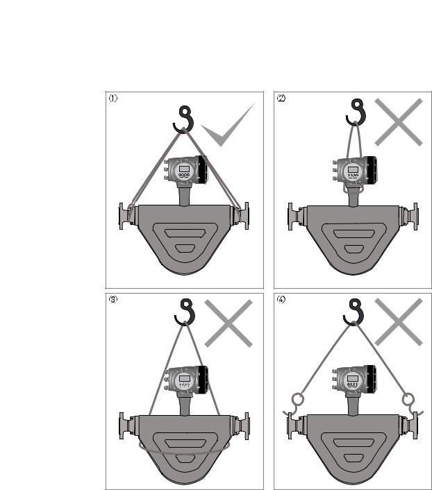
3.3 Handling
1Use a well maintained sling to lift the meter by the spigots.
2DO NOT lift the meter by the converter housing or the electronics stem.
3DO NOT lift the meter by the meter body.
4DO NOT lift the meter using the flange bolt holes.
07/2014 - 4001894003 - MA OPTIMASS 6000 R03 en |
www.krohne.com |
15 |
3 INSTALLATION |
|
|
OPTIMASS 6000 |
|
|
|
|
|
3.4 Installation conditions
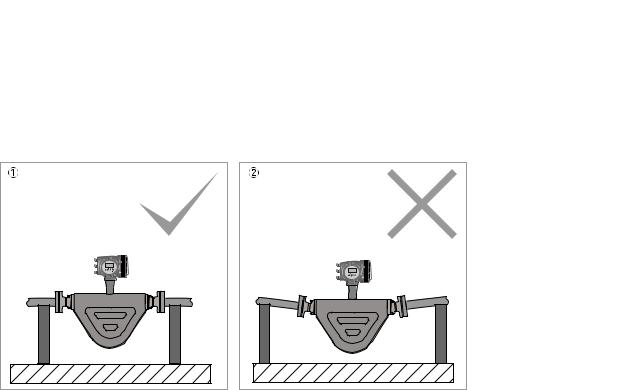
3.4.1 Supporting the meter
1Support the weight of the meter on the process pipework.
2DO NOT leave a long pipe run between the meter and the support. This can cause damage to the meter, especially on larger meter sizes.
16 |
www.krohne.com |
07/2014 - 4001894003 - MA OPTIMASS 6000 R03 en |

|
|
INSTALLATION 3 |
|
OPTIMASS 6000 |
|
|
|
|
3.4.2 Mounting the meter
Mounting positions
1The meter can be mounted at an angle but it is recommended that the flow is uphill.
2Avoid mounting the meter with the flow running downhill because it can cause siphoning. If the meter has to be mounted with the flow running downhill, install an orifice plate or control valve downstream of the meter to maintain backpressure.
3Horizontal mounting with flow running left to right.
4Avoid mounting meter with long vertical runs after the meter as it can cause cavitation. Where the installation includes a vertical run after the meter, install an orifice plate or control valve downstream to maintain backpressure.
5The meter can be mounted vertically but it is recommended that the flow is uphill.
6Avoid mounting the meter vertically with the flow running downhill. This can cause siphoning. If the meter has to be installed this way, install an orifice plate or control valve downstream to maintain backpressure.
07/2014 - 4001894003 - MA OPTIMASS 6000 R03 en |
www.krohne.com |
17 |
3 INSTALLATION |
|
|
OPTIMASS 6000 |
|
|
|
|
|
3.4.3 Gas / liquid build up
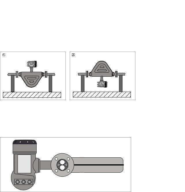
In certain applications, the design of the meter can cause either gas or liquid to build up in the measuring tube.
1Where liquids are being measured, mount the meter as shown. This will prevent gas building up in the measuring tube, when there is no flow.
2Where gases are being measured, mount the meter as shown. This will prevent liquids building up in the measuring tube, when there is no flow.
3.4.4Side mounting
The meter can be installed with the converter (or remote junction box) on the side of the meter so that the measuring tubes are sitting one above the other. Avoid this method of installation where there is a two phase process flow, or where the process fluid contains gas. If this situation cannot be avoided, please contact the manufacturer for advice.
18 |
www.krohne.com |
07/2014 - 4001894003 - MA OPTIMASS 6000 R03 en |
 Loading...