


OPTIMASS Handbook
•1000 Series Twin Straight Tube Coriolis Mass Flowmeter
•2000 Series Twin Straight Tube Coriolis Mass Flowmeter
•3000 Series Single Z Tube Coriolis Mass Flowmeter
•7000 Series Single Straight Tube Coriolis Mass Flowmeter
•8000/9000 Series Twin U Tube Coriolis Mass Flowmeter
2

CONTENTS |
OPTIMASS |
|
1. Safety Instructions |
|
|
1.1 |
Intended Use . . . . . . . . . . . . . . . . . . . . . . . . . . . . . . . . . . . . . . . . . . . . . . . . . . . . . . . . . . . . . |
.6 |
1.2 |
CE/EMC Standards/Approvals . . . . . . . . . . . . . . . . . . . . . . . . . . . . . . . . . . . . . . . . . . . . . . . |
6 |
1.3 |
PED Integrity . . . . . . . . . . . . . . . . . . . . . . . . . . . . . . . . . . . . . . . . . . . . . . . . . . . . . . . . . . . . . |
6 |
1.4 |
Secondary Containment & Burst Discs . . . . . . . . . . . . . . . . . . . . . . . . . . . . . . . . . . . . . . . . |
6 |
1.5 |
Explanation of Symbols Used . . . . . . . . . . . . . . . . . . . . . . . . . . . . . . . . . . . . . . . . . . . . . . . |
7 |
2. Instrument Description
2.1. Scope of Delivery . . . . . . . . . . . . . . . . . . . . . . . . . . . . . . . . . . . . . . . . . . . . . . . . . . . . . . . . .8
2.1.1 Flanged Versions . . . . . . . . . . . . . . . . . . . . . . . . . . . . . . . . . . . . . . . . . . . . . . . . . . .8
2.1.2 Hygienic Versions . . . . . . . . . . . . . . . . . . . . . . . . . . . . . . . . . . . . . . . . . . . . . . . . . . .8
2.1.3 Remote Field/Wall Converter . . . . . . . . . . . . . . . . . . . . . . . . . . . . . . . . . . . . . . . . .8
3. Installation Guidance
3.1 General Installation Information . . . . . . . . . . . . . . . . . . . . . . . . . . . . . . . . . . . . . . . . . . . . .9
3.2 General Installation Principles . . . . . . . . . . . . . . . . . . . . . . . . . . . . . . . . . . . . . . . . . . . . . .10
3.3 Storage . . . . . . . . . . . . . . . . . . . . . . . . . . . . . . . . . . . . . . . . . . . . . . . . . . . . . . . . . . . . . . . . . .10
3.4 Lifting . . . . . . . . . . . . . . . . . . . . . . . . . . . . . . . . . . . . . . . . . . . . . . . . . . . . . . . . . . . . . . . . . . .10
3.5 CSA Dual Seal . . . . . . . . . . . . . . . . . . . . . . . . . . . . . . . . . . . . . . . . . . . . . . . . . . . . . . . . . . . . .10
4. OPTIMASS 1000 (Twin Straight Tube Meter)
4.1 Specific Installation Guidelines . . . . . . . . . . . . . . . . . . . . . . . . . . . . . . . . . . . . . . . . . . . . . .12
4.2 Ambient/Prcocess Temperatures . . . . . . . . . . . . . . . . . . . . . . . . . . . . . . . . . . . . . . . . . . . .12
4.3 Pressure Equipment Directive . . . . . . . . . . . . . . . . . . . . . . . . . . . . . . . . . . . . . . . . . . . . . . .12
4.4 Secondary Pressure Containment . . . . . . . . . . . . . . . . . . . . . . . . . . . . . . . . . . . . . . . . . . . .13
4.5 Hygienic Applications . . . . . . . . . . . . . . . . . . . . . . . . . . . . . . . . . . . . . . . . . . . . . . . . . . . . . .13
4.6 Pressure Ratings . . . . . . . . . . . . . . . . . . . . . . . . . . . . . . . . . . . . . . . . . . . . . . . . . . . . . . . . . .14
4.7 Heating and Insulation . . . . . . . . . . . . . . . . . . . . . . . . . . . . . . . . . . . . . . . . . . . . . . . . . . . . .16
4.8 Purge Ports & Burst Discs . . . . . . . . . . . . . . . . . . . . . . . . . . . . . . . . . . . . . . . . . . . . . . . . . .18
4.9 Technical Data . . . . . . . . . . . . . . . . . . . . . . . . . . . . . . . . . . . . . . . . . . . . . . . . . . . . . . . . . . . .18
5. OPTIMASS 2000 (Twin Straight Tube Meter)
5.1 Specific Installation Guidelines . . . . . . . . . . . . . . . . . . . . . . . . . . . . . . . . . . . . . . . . . . . . . .25
5.2 Ambient/Process Temperatures . . . . . . . . . . . . . . . . . . . . . . . . . . . . . . . . . . . . . . . . . . . . .25
5.3 Pressure Equipment Directive . . . . . . . . . . . . . . . . . . . . . . . . . . . . . . . . . . . . . . . . . . . . . . .25
5.4 Secondary Pressure Containment . . . . . . . . . . . . . . . . . . . . . . . . . . . . . . . . . . . . . . . . . . . .26
5.5 Hygienic Applications . . . . . . . . . . . . . . . . . . . . . . . . . . . . . . . . . . . . . . . . . . . . . . . . . . . . . .26
5.6 Pressure Ratings . . . . . . . . . . . . . . . . . . . . . . . . . . . . . . . . . . . . . . . . . . . . . . . . . . . . . . . . . .27
5.7 Heating and Insulation . . . . . . . . . . . . . . . . . . . . . . . . . . . . . . . . . . . . . . . . . . . . . . . . . . . . .29
5.8 Purge Ports & Burst Discs . . . . . . . . . . . . . . . . . . . . . . . . . . . . . . . . . . . . . . . . . . . . . . . . . .32
5.9 Technical Data . . . . . . . . . . . . . . . . . . . . . . . . . . . . . . . . . . . . . . . . . . . . . . . . . . . . . . . . . . . .32
6. OPTIMASS 3000 (Single Z Shaped Tube Meter)
6.1 Specific Installation Guidelines . . . . . . . . . . . . . . . . . . . . . . . . . . . . . . . . . . . . . . . . . . . . . .37
6.2 Ambient/Process Temperatures . . . . . . . . . . . . . . . . . . . . . . . . . . . . . . . . . . . . . . . . . . . . .38
3
6.3 Pressure Equipment Directive . . . . . . . . . . . . . . . . . . . . . . . . . . . . . . . . . . . . . . . . . . . . . . .38
6.4 Secondary Pressure Containment . . . . . . . . . . . . . . . . . . . . . . . . . . . . . . . . . . . . . . . . . . . .39
6.5 Pressure Ratings . . . . . . . . . . . . . . . . . . . . . . . . . . . . . . . . . . . . . . . . . . . . . . . . . . . . . . . . .39
6.6 Heating & Insulation . . . . . . . . . . . . . . . . . . . . . . . . . . . . . . . . . . . . . . . . . . . . . . . . . . . . . . .41
6.7 Purge Port Meters & Burst Discs . . . . . . . . . . . . . . . . . . . . . . . . . . . . . . . . . . . . . . . . . . . .42
6.8 Technical Data . . . . . . . . . . . . . . . . . . . . . . . . . . . . . . . . . . . . . . . . . . . . . . . . . . . . . . . . . . . .43
7. OPTIMASS 7000 (Single Straight Tube Meter)
7.1 Specific Installation Guidelines . . . . . . . . . . . . . . . . . . . . . . . . . . . . . . . . . . . . . . . . . . . . . .46
7.2 Ambient/Process Temperatures . . . . . . . . . . . . . . . . . . . . . . . . . . . . . . . . . . . . . . . . . . . . .46
7.3 Pressure Equipment Directive . . . . . . . . . . . . . . . . . . . . . . . . . . . . . . . . . . . . . . . . . . . . . . .46
7.4 Secondary Pressure Containment . . . . . . . . . . . . . . . . . . . . . . . . . . . . . . . . . . . . . . . . . . . .47
7.5 Hygienic Applications . . . . . . . . . . . . . . . . . . . . . . . . . . . . . . . . . . . . . . . . . . . . . . . . . . . . . .47
7.6 Pressure Ratings . . . . . . . . . . . . . . . . . . . . . . . . . . . . . . . . . . . . . . . . . . . . . . . . . . . . . . . . . .48
7.7 Heating and Insulation . . . . . . . . . . . . . . . . . . . . . . . . . . . . . . . . . . . . . . . . . . . . . . . . . . . . .52
7.8 Purge Port and Burst Discs . . . . . . . . . . . . . . . . . . . . . . . . . . . . . . . . . . . . . . . . . . . . . . . . .56
7.9 Technical Data . . . . . . . . . . . . . . . . . . . . . . . . . . . . . . . . . . . . . . . . . . . . . . . . . . . . . . . . . . . .56
8. OPTIMASS 8000/9000 (Twin U Tube Meter)
8.1 Specific Installation Guidlines . . . . . . . . . . . . . . . . . . . . . . . . . . . . . . . . . . . . . . . . . . . . . . .62
8.2 Ambient/Process Temperatures . . . . . . . . . . . . . . . . . . . . . . . . . . . . . . . . . . . . . . . . . . . . .62
8.3 Pressure Equipment Directive . . . . . . . . . . . . . . . . . . . . . . . . . . . . . . . . . . . . . . . . . . . . . . .63
8.4 Secondary Pressure Containment . . . . . . . . . . . . . . . . . . . . . . . . . . . . . . . . . . . . . . . . . . . .63
8.5 Pressure De-rating . . . . . . . . . . . . . . . . . . . . . . . . . . . . . . . . . . . . . . . . . . . . . . . . . . . . . . . .63
8.6 Hygienic and Sanitary Connections . . . . . . . . . . . . . . . . . . . . . . . . . . . . . . . . . . . . . . . . . . .66
8.7 Heating and Insulation . . . . . . . . . . . . . . . . . . . . . . . . . . . . . . . . . . . . . . . . . . . . . . . . . . . . .67
8.8 Purge Ports and Burst Discs . . . . . . . . . . . . . . . . . . . . . . . . . . . . . . . . . . . . . . . . . . . . . . . .69
8.9 Technical Data . . . . . . . . . . . . . . . . . . . . . . . . . . . . . . . . . . . . . . . . . . . . . . . . . . . . . . . . . . . .70
9. MFC 300 Converter
9.1 Electrical Connections . . . . . . . . . . . . . . . . . . . . . . . . . . . . . . . . . . . . . . . . . . . . . . . . . . . . . .73 9.2 Mounting MFC 300W . . . . . . . . . . . . . . . . . . . . . . . . . . . . . . . . . . . . . . . . . . . . . . . . . . . . . . .73 9.3 Mounting MFC 300F . . . . . . . . . . . . . . . . . . . . . . . . . . . . . . . . . . . . . . . . . . . . . . . . . . . . . . . .73 9.4 Changing Display Orientation . . . . . . . . . . . . . . . . . . . . . . . . . . . . . . . . . . . . . . . . . . . . . . . .74 9.5 Mains Power Connection versions C, F and W . . . . . . . . . . . . . . . . . . . . . . . . . . . . . . . . . .75 9.6 Connection of Remote Sensors . . . . . . . . . . . . . . . . . . . . . . . . . . . . . . . . . . . . . . . . . . . . . .77
9.6.1 MFC 300F . . . . . . . . . . . . . . . . . . . . . . . . . . . . . . . . . . . . . . . . . . . . . . . . . . . . . . . . .78 9.6.2 MFC 300W . . . . . . . . . . . . . . . . . . . . . . . . . . . . . . . . . . . . . . . . . . . . . . . . . . . . . . . . .78 9.6.3 MFC 300R . . . . . . . . . . . . . . . . . . . . . . . . . . . . . . . . . . . . . . . . . . . . . . . . . . . . . . . . .79
9.7 I/O Assemblies . . . . . . . . . . . . . . . . . . . . . . . . . . . . . . . . . . . . . . . . . . . . . . . . . . . . . . . . . . . .80
9.7.1 Basic I/O . . . . . . . . . . . . . . . . . . . . . . . . . . . . . . . . . . . . . . . . . . . . . . . . . . . . . . . . . .81
9.7.2 Fixed I/O . . . . . . . . . . . . . . . . . . . . . . . . . . . . . . . . . . . . . . . . . . . . . . . . . . . . . . . . . .81
9.7.3 Modular I/O . . . . . . . . . . . . . . . . . . . . . . . . . . . . . . . . . . . . . . . . . . . . . . . . . . . . . . . .81
9.8 Operating Data I/O . . . . . . . . . . . . . . . . . . . . . . . . . . . . . . . . . . . . . . . . . . . . . . . . . . . . . . . .83
9.8.1 Current Output . . . . . . . . . . . . . . . . . . . . . . . . . . . . . . . . . . . . . . . . . . . . . . . . . . . . .83
4
9.8.2 Pulse & Frequency Output . . . . . . . . . . . . . . . . . . . . . . . . . . . . . . . . . . . . . . . . . . .84 9.8.3 Status Output and Limit Switches . . . . . . . . . . . . . . . . . . . . . . . . . . . . . . . . . . . . .85 9.8.4 Control Input . . . . . . . . . . . . . . . . . . . . . . . . . . . . . . . . . . . . . . . . . . . . . . . . . . . . . . .86
9.9 Connection Diagrams (Outputs/Inputs) . . . . . . . . . . . . . . . . . . . . . . . . . . . . . . . . . . . . . . . .86 9.9.1 MFC300 W Connection Block . . . . . . . . . . . . . . . . . . . . . . . . . . . . . . . . . . . . . . . . .87 9.9.2 Basic I/O Connection Diagrams . . . . . . . . . . . . . . . . . . . . . . . . . . . . . . . . . . . . . . .87 9.9.3 Modular I/O & BUS I/O Connection Diagrams . . . . . . . . . . . . . . . . . . . . . . . . . . .89 9.9.4 HART . . . . . . . . . . . . . . . . . . . . . . . . . . . . . . . . . . . . . . . . . . . . . . . . . . . . . . . . . . . . .91
9.10 Dimensions and Weights . . . . . . . . . . . . . . . . . . . . . . . . . . . . . . . . . . . . . . . . . . . . . . . . . . .92
9.11 Technical Data . . . . . . . . . . . . . . . . . . . . . . . . . . . . . . . . . . . . . . . . . . . . . . . . . . . . . . . . . . .95
10. Start Up
10.1 Operator Control of the Converter . . . . . . . . . . . . . . . . . . . . . . . . . . . . . . . . . . . . . . . . . . .99
10.2 Time Out Function . . . . . . . . . . . . . . . . . . . . . . . . . . . . . . . . . . . . . . . . . . . . . . . . . . . . . . . .101
10.3 Menu Structure . . . . . . . . . . . . . . . . . . . . . . . . . . . . . . . . . . . . . . . . . . . . . . . . . . . . . . . . . .102
10.4 Table of Settable Functions . . . . . . . . . . . . . . . . . . . . . . . . . . . . . . . . . . . . . . . . . . . . . . . .104
10.5 Description of Functions . . . . . . . . . . . . . . . . . . . . . . . . . . . . . . . . . . . . . . . . . . . . . . . . . . .118
11. Service and Troubleshooting
11.1 |
Diagnostic Functions . . . . . . . . . . . . . . . . . . . . . . . . . . . . . . . . . . . . . . . . . . . . . . . . . . . . . |
130 |
11.2 |
Functional Tests and Troubleshooting . . . . . . . . . . . . . . . . . . . . . . . . . . . . . . . . . . . . . . . |
131 |
11.3 |
Driver or Sensor Coil . . . . . . . . . . . . . . . . . . . . . . . . . . . . . . . . . . . . . . . . . . . . . . . . . . . . . . |
133 |
11.4 |
Replacing the Sensor or Converter Electronics . . . . . . . . . . . . . . . . . . . . . . . . . . . . . . . . |
136 |
11.5 |
Status Messages and Diagnostics Information . . . . . . . . . . . . . . . . . . . . . . . . . . . . . . . . |
138 |
12. Additional Information
12.1 External Standards . . . . . . . . . . . . . . . . . . . . . . . . . . . . . . . . . . . . . . . . . . . . . . . . . . . . . . .142
12.2 Certificates . . . . . . . . . . . . . . . . . . . . . . . . . . . . . . . . . . . . . . . . . . . . . . . . . . . . . . . . . . . . . .142
12.3 Krohne Publications . . . . . . . . . . . . . . . . . . . . . . . . . . . . . . . . . . . . . . . . . . . . . . . . . . . . . .142
12.4 Declaration of Cleanliness Certificate . . . . . . . . . . . . . . . . . . . . . . . . . . . . . . . . . . . . . . . .143
12.5 Specimin Certificate . . . . . . . . . . . . . . . . . . . . . . . . . . . . . . . . . . . . . . . . . . . . . . . . . . . . . .143
5

1 |
SAFETY INSTRUCTIONS |
OPTIMASS |
|
|
|
Congratulations on purchasing this high quality product. To get the best out of your mass flowmeter, please take some time to read through this handbook which describes the many features and options available. Please refer to the index for a list of detailed topics.
If applicable, a separate document is supplied that describes hazardous area information.
1.1 Intended Use
The OPTIMASS mass flowmeter family is designed for the direct measurement of mass flow rate, product density and product temperature. Indirectly, it also enables measurement of parameters such as: total mass; concentration of dissolved substances and the volume flow.
For use in hazardous areas, special codes and regulations are applicable which are specified in a separate handbook.
Responsibility as to the suitability and intended use of our instruments rests solely with the purchaser. The supplier does not accept any liability resulting from misuse by the customer.
Improper installation and operation of the flow meters may lead to loss of warranty. Warranty is also null and void if the instrument is damaged or interfered with in any way.
In addition, the “general conditions of sale” which forms the basis of the purchase agreement are applicable.
If you need to return your OPTIMASS flow meters to KROHNE, please complete the form on the last page of this handbook and return it with the meter to be repaired. KROHNE regrets that it cannot repair or check your flow meter unless accompanied by a completed form.
1.2 CE/EMC Standards/Approvals
The OPTIMASS family with the MFC 300/010 signal converter meets all the requirements of the EU-EMC and PED Directives and bears the CE Symbol.
The OPTIMASS system is approved for hazardous duty installations to the harmonised European Standards (ATEX) to Factory Mutual (FM) and CSA (Canadian Standards).
Technical data subject to change without notice
It should be noted that this handbook MUST be read in conjunction with the following additional documentation:
•Hazardous Areas Handbook.
•Communications Handbook.
•Concentration Handbook.
•Corrosion Guidelines.
1.3 PED Integrity
To ensure the PED integrity of the meter, you MUST ensure that the serial numbers on both the conveter (or remote terminal box) data label and the sensor match.
1.4 Secondary Containment & Burst Discs
Where the meter is being used to measure:
•high pressure gases
•gases kept as liquids by high pressure
and/or where there is a risk of tube failure because of:
•the use of corrosive and/or errosive process fluids
•frequent pressure and/or temperature shocking
•seismic or other shock loading
Krohne strongly recommends that a secondary containment option is purchased. Where the above situation applies and the process pressure exceeds the secondary pressure containment, Krohne recommends that the burst disc option is also purchased. For more information, please contact Krohne Ltd
6

1.5 Explanation of Symbols Used
The following is a guide to the meaning of the symbols used in this handbook.The symbols fall into two types. The rectangular symbols with blue background draws the reader’s attention to general points of information. The triangular symbols with yellow background draw the reader’s attention to hazards or hazardous situations.
General Information
Information is important to the installation/operation of the meter.
General Warning |
Risk of damage to the meter or installation. |
EX - Hazardous Area Warning
Instruction MUST be observed in order to comply with Hazardous Areas Certification.
High Voltage |
Risk of electric shock. |
General Hazard |
Non specific hazard that could result in injury. |
Hot Surface or High Temperature |
Risk of burning. |
Heavy Item |
Risk of injury. |
7

2 |
INSTRUMENT DESCRIPTION |
OPTIMASS |
|
|
|
2.1 Scope of Delivery
When unpacking your meter, please ensure that no visible damage has occurred during transportation. If damage has occurred, please contact the carrier for claims.
Your high quality instrument has been fully tested and checked before shipping. The following items should be included with your instrument unless otherwise requested:
1.OPTIMASS Mass Flow Meter
2.Separate Converter with remote converter wall mount (not for compact version)
3.CD-ROM & Quick Start Guides
4.Screw driver for terminal connections
5.Calibration certificate
6.Factory and Material certification, if ordered.
If any of these items are missing, please contact your nearest KROHNE Office or representative (see back page).
2.1.1 Flange Versions
If your meter has been ordered with a flange connection, this will be supplied as per your order and the flange specification is stamped on the outer edge of the flange.
Please check this specification against your original order and refer to the appropriate section in this handbook.
2.1.2 Hygienic Versions
If your meter was ordered with a hygienic connector, it should be noted that the ‘O’ ring seals between the meter and process pipework are NOT normally supplied.
If the hygienic connection is via an adaptor, then ‘O’ rings (material EPDM) are supplied in order to make the connection between the meter and the adaptor. Please note that other materials are available on request.
‘O’ rings are not normally supplied for the seal between the adaptor connection and process pipework.
Adaptor connections may also be supplied loose, dependng upon type supplied.
For DIN11864-2 connections, ‘O’ rings and counter flanges are not supplied as standard but are available on request.
2.1.3 Remote Field/Wall/Rack Conveter
The OPTIMASS range of massflow meters are normally supplied with the converter integrally fitted. If you have specified a remote converter, the meter will be supplied with the converter as a separate unit, together with a wall/pipe mounting bracket and a connection box mounted to the meter.
In order to comply with 3A approval, all unused holes MUST be plugged and unused threads MUST be covered or removed!
If ordered with the meter, cabling is supplied loose and IS NOT pre-prepared!
Wall Converter
If specified at the time of ordering, the meter will be supplied with a plastic wall mounted converter that can be mounted on a wall or a pipe The housing material is Polyamide - polycarbonate.
Please note that the wall converter has not been 3A approved for hygienic applications.
19” Rack Mount Converter
If specified at the time of ordering, the meter will be supplied with a 19” rack mounted converter
8
3 |
INSTALLATION GUIDANCE |
OPTIMASS |
|
|
|
3.1 General Installation Information
The OPTIMASS mass flow meters provide high accuracy and excellent repeatability. Narrow band pass digital filtering, and the mathematically modelled internal primary head design with AST (Adaptive Sensor Technology) for the OPTIMASS sensor family provide exceptional immunity to external disturbances caused by vibrations from nearby process equipment.
The accuracy of the flow meter is not affected by velocity profile.
The following installation guidelines are practical to implement, particularly if planned before the OPTIMASS meter is first installed. For further dimensions or connections, please refer to the relevant section.
For the OPTIMASS, in general, no special mounting requirements are necessary. However, good general engineering practice for the installation of flow meters should still be observed.
The general guidelines described in this section are valid for the complete OPTIMASS family of mass flow meters
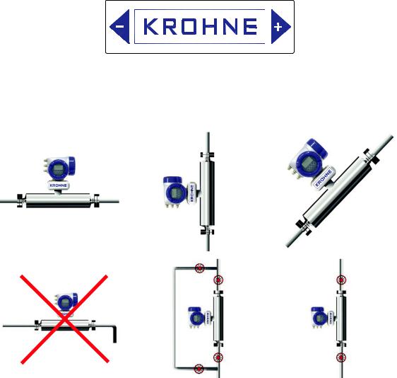
•The mass flow meters do not require any straight inlet or outlet runs.
•Due to the weight of the meters we recommend the use of supports.
•It is permissible to support the body of the meter.
•The meter can be installed horizontally, in an upward sloping pipeline or vertically. For best results, a vertical installation with flow in an upward direction is recommended.
This label on the meter shows the flow direction programmed into the converter in function C.1.3.1
As default this is always in the direction of the ‘+’ arrow, i.e. left-to right as the label is viewed.
3.2 General Installation Principles
1 |
|
2 |
|
3 |
|
|
|
|
|
4 |
|
5 |
|
6 |
|
|
|
|
|
9
1Horizontal intalation with flow from left to right
2Vertcial installation with flow uphill
3Angled installation with flow uphill
4Horizontal installation with long vertical drops after the meter ARE NOT recommended
5 6 Vertical installations with isolation valves fitted for setting the zero calibration. It is recommended that a valve is fitted below the meter to prevent a reverse flow when the pump is switched off.
Notes:
Avoid long vertical runs after the meter (4). They can cause siphoning and therefore measurement errors. If long vertical runs are unavoidable, then you should use a valve or orifice plate downstream of the mter in order to the restrict flow.
Avoid mounting the meter at the highest point in the pipeline. Air or gas can accumulate here and cause faulty measurements.
3.3 Storage
If the meter is to be stored prior to installation, it is recomended that the meter is stored in its original packaging and that the ambient temperature range does not exceed -50°C or 85°C
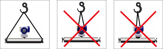
3.4 Lifting
1 |
2 |
3 |
1Use a well maintained sling to lift the meter by the spigots
2DO NOT lift the meter by the electronics housing.
3 DO NOT lift the meter by the electronics stem.
NOTE:
The 1000 and 2000 meters have 4 eye holes on the outer tube, 2 each end. These can be used to lift the meter into place on vertical installations, where the meter is supplied with hygienic connections. Please be aware, that they ARE NOT suitable for lifting the meter where is has been supplied with [heavier] flange connections. It is the user’s responsibility to use suitable lifting equipment.
3.5 CSA Dual Seal
To cover the requirements of ANSI/ISA -12.27.01-2003 “Requirements for Process Sealing Between Electrical Systems and Flammable or Combustible Process Fluids” a secondary seal is incorporated into all Optimass/gas products. If the primary seal fails, the secondary seal will prevent escaping fluid reaching the electronic compartment.
OPTIMASS 1000, 2000, 3000, 7000, 8000, 9000
Liquids (Example model code: OPTIMASS 1000C S25 – LIQUID)
Pressure/Temperature data:
OPTIMASS 1000 / 1300 / 1010 -40°C...130°C and 100...10,000 kPa
OPTIMASS 2000 / 2300 / 2010 -45°C...130°C and 100...14,000 kPa
OPTIMASS 3000 / 3300 / 3010 -40°C...150°C and 100...15,000 kPa
OPTIMASS 7000 / 7300 / 7010 -40°C...150°C and 100...10,000 kPa
10
OPTIMASS 8000 / 8300 / 8010 -180°C...230°C and 100 to 26,000 kPa
OPTIMASS 9000 / 9300 / 9010 0°C...350°C and 100 to 26,000 kPa
If the primary seal fails, the casing of the meter will fill with liquid and the meter will stop working. The meter will notify the operator by going into <start up> mode and a diagnostic error will be shown on the MFC300 or PLC display. This is an indication that the primary seal (tube/s) has failed and the status of the meter should be checked.
Meter Status:
The meter will also go into <Start up> mode if the primary seal (tube/s) fail, or are not completely filled with fluid. For example, if the meter is drained or re/filled. To check the status of the meter, drain and re/fill with fluid and note the MFC300 or PLC display. See section11.5 for a list of status messages and diagnistics information.
If the meter remains in <Start Up> mode you MUST assume that the primary seal (tube/s) has failed and the appropriate action MUST be taken.
Gases (Example model code: OPTIMASS 1000C S25 – GAS)
Pressure/Temperature data:
OPTIMASS 1000 / 1300 / 1010 -40°C...130°C and +500 to +10,000 kPa
OPTIMASS 2000 / 2300 / 2010 -45°C...130°C and +500 to +15,000 kPa
OPTIMASS 3000 / 3300 / 3010 -40°C...150°C and +500 to +15,000 kPa
OPTIMASS 7000 / 7300 / 7010 -40°C...150°C and +500 to +10,000 kPa
OPTIMASS 8000 / 8300 / 8010 -180°C...30°Cand +2000 to +26,000 kPa
OPTIMASS 9000 / 9300 / 9010 0°C...350°C and +2000 to +26,000 kPa
Pressures and/or temperatures may be further limited by tube, temperature, connection and Ex limits. Consult the meter data plates and relevant documentation for full details.
On all meters operating on gas measurement the casing of the meter is fitted with a burst disc. If the the primary seal (tube/s) fails leakage will occur from the burst disc.
Install the meter so that the burst disc is pointing away from personnel.
Regular Maintenance of Burst Disc:
Carry out regular maintenance checks on burst discs for leakage and/or blockages.
On all OPTIMASS meters, the primary seal is considered to be the measuring tube of the meter. The materials of construction of the measuring tube/s are described within the relevant sections of this handbook and the customer’s product and any other fluid flowing through the tube must be compatible with the material of construction.
If failure of the primary seal is suspected then the process line should be de-pressurised and the meter removed as soon as it is safe to do so. Please then contact Krohne customer service for servicing or replacement of the meter.
11

4 |
OPTIMASS 1000 |
OPTIMASS |
|
|
|
4.1 Specific Installation Guidelines
•Tighten flange bolts evenly.
•Observe the pipe end loads as shown in s. 4.6
•It is permissible to support the weight of the meter on the body.
•Use of standard pipework reducers at the flange is allowed. Avoid extreme changes in pipe size (step changes).
•The use of flexible hoses directly at the meter is permitted.
•The meter can be installed so that the converter is on the side of the meter, resulting in the measuring tubes on top of each other, unless gases or solids are being measured.
•The 1000 series has exceptional immunity to cross-talk, therefore allowing meters to be used in series.
4.2 Ambient / Process temperatures
The specified and approved ambient and process temperatures must be observed.
|
|
|
SS318L |
|
||
|
|
|
|
|||
|
|
°C |
°F |
|||
|
|
|
|
|
||
Process |
All meters |
-45... |
+130 |
-49 |
...266 |
|
|
|
|
|
|
|
|
|
Compact Al. |
-40... |
+60 |
40... |
+140 |
|
|
|
|
|
|
|
|
Ambient |
Compact Al. with certain I/O options (consult Krohne) |
-40... |
+65 |
-40... |
+149 |
|
|
|
|
|
|
||
Compact SS |
-40 |
+55 |
-40 |
+131 |
||
|
||||||
|
|
|
|
|
|
|
|
Remote |
-40... |
+65 |
-40... |
+149 |
|
|
|
|
|
|
|
|
Note:
For additional temperature limits in hazardous area applications, reference should be made to the publication “Guidelines for the use of Coriolis Meters in Hazardous Areas”.
Where meters are mounted in direct sunlight, it is recommended to install a sunshade. This is particularly important in countries with high ambient temperatures.
The maximum differential temperature between the process and ambient temperature without insulation is 110°C or 200°F.
To avoid thermal shock, the meter MUST not be subject to rapid changes in process tempratures and reference should be made to the following table
Meter |
Max. Temperature Shift |
|
|
S15 & S25 |
80°C |
|
|
S40 & S50 |
110°C |
|
|
Operation outside these limits may result in shifts in density and mass flow calibration. Repeated shocking may also lead to premature failure of the meter!
4.3 Pressure Equipment Directive (PED) requirements
To comply with the requirements of the PED in Europe, the following information is provided to assist the plant engineer in installing the meter:
Measuring tube: |
Sealing Faces: |
|
|
Stainless Steel UNS 31803 |
Stainless Steel 316L |
|
|
The outer cylinder 304 / 304L is dual certified (Optional outer cylinder of 316/316L). This also applies to PED certified housings.
Wiring feedthrough is made of Epoxy (or PEEK) with 2 ‘O’ ring seals in FPM / FKM & Hydrogenated Nitrile.
12
Flanges all 316 / 316 L dual certified.
Hygienic Connections are 316L
Optional heating jacket 316 / 316L
Note: Outer cylinder is in contact with heating medium
4.4 Secondary Pressure containment
The OPTIMASS 1000 meters are supplied (as standard) without certified housings that have a typical burst pressure >100 barg.
Options are available with PED certified housings, with the following pressure ratings:
304/304L and 316/316L: 63 bar @20°C 580 psi @ 68°F
316/316L: 100 bar @20°C 1450 psi @ 68°F
If the user suspects that the primary tube has failed, the unit must be depressurised and removed from service as soon as it is safe to do so.
Note:
In the 1000 series there is a high pressure wire feed through with ‘O’ rings that might not be compatible with the process fluid for an extended period if a primary tube fails.
It is the user’s responsibility to ensure that the materials used are compatible with this product.
Other ‘O’ ring materials are available on request.
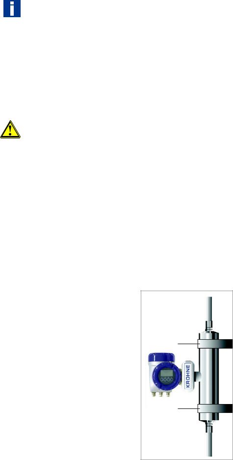
4.5 Hygienic Applications
The OPTIMASS 1000 series is available with a variety of hygienic process connectors.
When installing / using meters with hygienic process connectors, support /clamp the meter properly. The meters are heavy and could injure when disconnected from the adjacent pipe work.
The recommended method of installation is to mount the meter against a support / wall with the body of the meter supported / clamped. The process pipe work can then be supported off the meter. The meter is too heavy to be supported from the thin walled piping usually associated with the hygienic industry
1
2
1 2 Meter Supports
13

The 3A approval for the 1000 series requires that it is “self draining”. Install the meter vertically with the flow running uphill.
Installation lengths
For installation lengths, please see section 4.9
Please check with KROHNE if you are unsure of the installation length. Many meters are built to customer requirements / specifications especially where special hygienic process nectors have been adapted to the meter. As these are normally non-standard, the installation length will not be given in the technical data
It is also recommended that the seals be replaced regularly to maintain the hygienic integrity of the connection.
Unless specifically requested, internal surfaces are not polished and no warranty is made as to the surface finish.
If polishing option and /or EHEDG, ASME Bio-Processing or 3A approvals was selected at time of order, all product contact surfaces are polished 0.5 micrometer Ra (20CLa) finish or better.
4.6 Pressure ratings
Tubes and secondary |
100 bar at 20°C |
(1450 psi at 68°F) |
|
pressure containment 100 barg |
|||
|
|
||
|
|
||
De-rated to |
80 bar at 130°C (1160 psi at 266°F) |
||
|
|
|
|
Heating Jacket |
10 bar at 130°C |
(145 psi at 266°F) |
|
|
|
|
|
Secondary pressure containment 63 barg |
63 bar at 20°C |
(914 psi at 68°F) |
|
|
|
|
|
De-rated to |
50 bar at 130°C |
(725 psi at 266°F) |
|
|
|
|
|
Meter data plates are stamped with maximum pressure rating at both 20°C (68°F) and max. operating temperature of connection, primary tube or secondary pressure containment whichever is the lower.
Maximum pipe work forces
|
20°C |
130°C |
||
|
|
|
|
|
|
40 bar |
100 bar |
32 bar |
80 bar |
|
|
|
|
|
Size |
Max Load |
Max Load |
Max Load |
Max Load |
|
|
|
|
|
15 |
25 kN |
17 kN |
18 kN |
12 kN |
|
|
|
|
|
25 |
38 kN |
19 kN |
28 kN |
12 kN |
|
|
|
|
|
40 |
48 kN |
15 kN |
35 kN |
7 kN |
|
|
|
|
|
50 |
99 kN |
20 kN |
72 kN |
8 kN |
|
|
|
|
|
|
|
Flange Connections |
|
|
|
|
|
|
|
These loads are roughly equivalent to the max axial loading allowed in an un-radiographed butt weld in a 316L schedule 40 pipe.
Loads given are maximum static loads. If loads are cycling, particularly between tension and compression, these loads should be reduced.
Please consult KROHNE for more information.
14
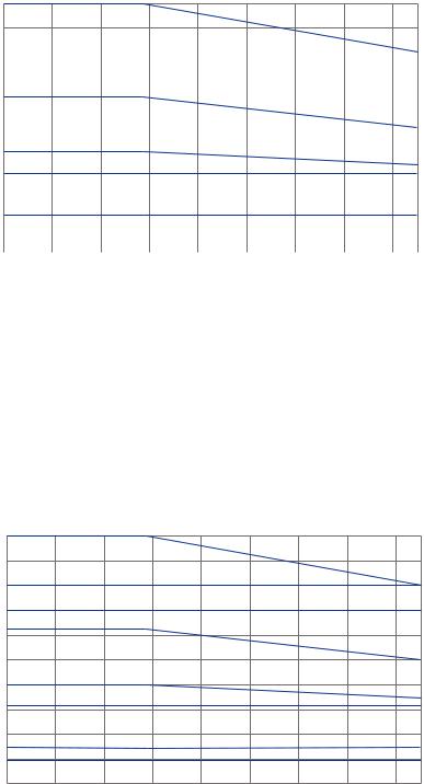
Pressure de-rating (barg)
P(barg)
100
90
1
80 |
|
|
|
2 |
|
|
|
||
70 |
|
|
|
3 |
|
|
|
||
60 |
|
|
|
4 |
|
|
|||
50 |
|
|
|
|
|
|
|||
40 |
|
|
|
|
|
5 |
|||
30 |
|
|
||
|
|
|
6 |
|
|
|
|||
20 |
|
|
|
|
|
7 |
|||
10 |
|
|
||
|
|
|
8 |
|
|
|
|
||
0 |
|
|
|
|
|
20 40 60 80 100 120 130 |
|||
-40 -20 0 |
||||
TOC
1 Measuring tubes (PED & CRN 15/25) and outer cyclinder 316 (100 barg PED option) PN100, DIN2637, PN100
2 CRN S40 measuring tube
3 CRN S30 measuring tube
4 Outer cylinder 304 & 316 (63 barg PED option), DIN 2636, PN 63 5 DIN 2635 PN 40
6 JIS 20K
7 JIS 10K
8 Hygienic connection
Pressure de-rating (psig)
P (psig)
1450 |
|
|
|
|
|
|
|
|
1305 |
|
|
|
|
|
|
|
1 |
1160 |
|
|
|
|
|
|
|
|
|
|
|
|
|
|
|
2 |
|
1015 |
|
|
|
|
|
|
|
3 |
870 |
|
|
|
|
|
|
|
|
725 |
|
|
|
|
|
|
|
4 |
580 |
|
|
|
|
|
|
|
5 |
435 |
|
|
|
|
|
|
|
|
|
|
|
|
|
|
|
6 |
|
290 |
|
|
|
|
|
|
|
7 |
145 |
|
|
|
|
|
|
|
|
|
|
|
|
|
|
|
8 |
|
0 |
-20 |
0 |
20 |
40 |
60 |
80 |
100 |
120 130 |
-40 |
||||||||
|
|
|
|
|
T OF |
|
|
|
1 Measuring tubes (PED & CRN 15/25) and outer cyclinder 316 (1450 psig PED option) 2 CRN S40 measuring tube
3 CRN S30 measuring tube
4 ASME 600 lbs
5 Outer cyclinder 304 & 316 (914 psig PED option) 6 ASME 300 lbs
7 ASME 150 lbs
8 Hygienic connection
15
DIN flange ratings based on EN 1092-1: 2001 table 18, 1% proof stress material group 14EO ASME flange ratings based on ASME B16.5: 2003 table 2 material group 2.2
JIS flange rating based on JIS 2220: 2001 table 1 division 1 material group 022a
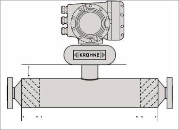
4.7 Heating and insulation
There are several ways to heat the meter. In most cases heating is unnecessary as the meter is designed as such that very little heat is lost or gained through the outer cylinder.
Insulation
Where insulation is required a variety of materials may be used to insulate the meter. Care must be taken not to insulate the meter above the halfway mark of the electronics support post as shown.
Electrical Heating
Electrical tape heating may be used. Care should be taken to only heat the sections where the best effect will be achieved. Do not heat above the converter mount centre line See illustration.
1
|
|
|
|
|
|
|
|
|
2 |
|
|
3 |
|
|
|
2 |
|
|
|
|||||||
1 Max insulation depth
2 Heated Areas
3 Do NOT heat this area
When insulating please observe guidelines as per insulation section.
Size |
DIM 2 |
|
|
15 |
65 mm |
|
|
25 |
75 mm |
|
|
40 |
110 mm |
|
|
50 |
125 mm |
|
|
16
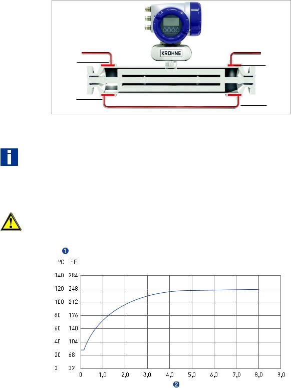
Liquid / Steam heating jacket
The meter can be supplied with a heating jacket. This jacket is designed to minimise the differential stress across the meter where differences in temperature between outer cylinder and measuring tube exist.
The connections to the heating jacket are NPT or Ermeto sockets.
It is recommended that reinforced flexible hoses be used to connect the heating jacket to the heat source.
1 |
2 |
|
3 |
4 |
|
1 2 3 4 Connection Points
Important:
Always heat the jacket to working temperature before flowing product in measuring tube.
Avoid the use of fluids that can cause crevice corrosion.
Although all the jacket materials are 316L, the outer cylinders are 304L (Optional 316L).
Connections should be made to ensure all air can be vented on liquid systems and all condensate can be drained on steam systems.
Note :
The maximum heating medium pressure and temperature for heating jackets is 10 bar at 130°C or 145 psig at 266°F.
Heating Times (based on heating jacket operating at maximum temperature)
1 Temperature at centre of measuring tube
2 Time (hours)
Cooling: please consult KROHNE if cooling medium is to be used in the heating jacket.
17

4.8 Purge Port Meters and Burst Disc Meters
Purge Port Options
If the purge port option was selected at time of order, then your meter will be fitted with ½” NPT female connections – these will be clearly identified. These connections are sealed with NPT plugs and PTFE tape.
Important:
Do not remove these plugs.
The meter is factory sealed with a dry nitrogen gas fill and any ingress of moisture will damage the meter. The plugs should only be removed to purge the inside of the meter case of any product if it is suspected that the primary measuring tube has failed. If it is suspected that the primary tube has failed, depressurise and remove the meter from service, as soon as it is safe to do so.
Burst Disc meters (Meters up to size 25 only)
OPTIMASS 1000 meters that have been ordered with a burst (rupture) disc will be suppled with the disc fitted. The disc is fitted when the operating pressure of the measuring tube exceeds the design pressure of the secondary containment. The disc failure pressure is 20bar @ 20°C.
Important:
The burst disc is suitable for the designed application according to the process conditions and flow rates as per original order. If conditions alter, consult KROHNE for further advice regarding suitability of disc fitted.
If the product is in any way hazardous, it is strongly recommended that an exhaust tube is connected to the NPT male thread of the burst disc so that the discharge can be piped to a safe area. This tube should be large enough that pressure cannot build up in the meter case.
Ensure arrow on burst disc is pointing away from meter
4.9 Technical Data
Maximum Flow Rates
|
15 |
25 |
40 |
50 |
|
|
|
|
|
Kg/h |
6,500 |
27,000 |
80,000 |
170,000 |
|
|
|
|
|
Lbs/min |
239 |
992 |
2,940 |
6,247 |
|
|
|
|
|
Minimum flow rate
Depending on measuring error required.
Weights (PN40 flanges) |
|
|
|
|
|
|
|
|
|
|
|
|
|
|
|
|
|
|
|
|
|
|
|
|
|
|
|
15 |
|
25 |
40 |
|
|
50 |
||||
|
|
|
|
|
|
|
|
|
|
|
|
|
|
kg |
|
lbs |
kg |
|
lbs |
kg |
|
lbs |
kg |
|
lbs |
|
|
|
|
|
|
|
|
|
|
|
|
|
Compact with aluminium MFC 300 |
13.5 |
|
30 |
16.5 |
|
36 |
29.5 |
|
65 |
57.5 |
|
127 |
|
|
|
|
|
|
|
|
|
|
|
|
|
Compact with SS MFC 300 |
18.8 |
|
41 |
21.8 |
|
48 |
34.8 |
|
77 |
62.8 |
|
138 |
|
|
|
|
|
|
|
|
|
|
|
|
|
Remote with aluminium J box |
11.5 |
|
25 |
14.5 |
|
32 |
25.5 |
|
56 |
51.5 |
|
113 |
|
|
|
|
|
|
|
|
|
|
|
|
|
Remote with SS J box |
12.4 |
|
27 |
15.4 |
|
34 |
26.4 |
|
58 |
52.4 |
|
115 |
|
|
|
|
|
|
|
|
|
|
|
|
|
18
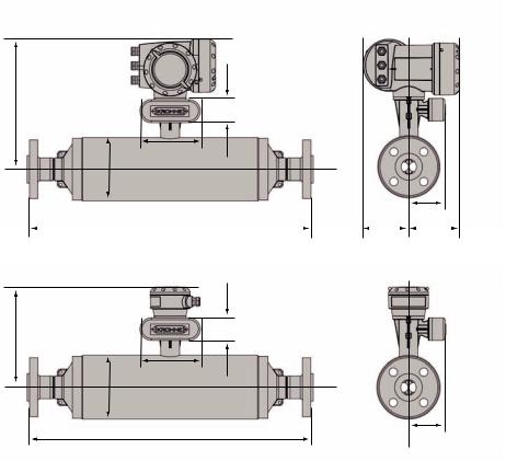
Dimensions
Flanged versions
1
B1
F
E
A
G
D |
|
H |
|
I |
2
B2
A
G
D
1 Compact version
2 Remote Version
19
Metric (mm) |
|
|
|
|
|
|
|
|
|
|
|
|
|
|
|
|
|
|
||
|
|
|
|
|
|
|
|
|
|
|
|
|
|
|
|
|
|
|
|
|
DN15 |
|
|
|
|
|
|
|
|
|
|
|
|
|
|
|
|
|
|
|
|
|
|
|
|
|
|
|
|
|
|
|
|
|
|
|
|
|
|
|
|
|
|
|
DN 15 PN40 |
DN 25 PN40 |
DN 15 PN100 |
DN 25 PN100 |
½" ASME 150 |
½" ASME 300 |
½" ASME 600 |
¾" ASME 150 |
|
¾" ASME 300 |
¾" ASME 600 |
1” ASME 150 |
1” ASME 300 |
1” ASME 600 |
|
15A JIS 20K |
25A JIS 20K |
|
|
|
|
|
|
|
|
|
|
|
|
|
|
|
|
|
|
|
|
|
|
|
A |
|
|
|
|
|
|
|
|
101.6 |
|
|
|
|
|
|
|
|
|
||
|
|
|
|
|
|
|
|
|
|
|
|
|
|
|
|
|
|
|
|
|
B1 / B2 |
|
|
|
|
|
|
|
|
311 / 231 |
|
|
|
|
|
|
|
|
|
||
|
|
|
|
|
|
|
|
|
|
|
|
|
|
|
|
|
|
|
|
|
D |
|
498 |
503 |
513 |
538 |
518 |
528 |
541 |
528 |
|
538 |
550 |
534 |
546 |
558 |
|
498 |
503 |
|
|
|
|
|
|
|
|
|
|
|
|
|
|
|
|
|
|
|
|
|
|
|
DN25 |
|
|
|
|
|
|
|
|
|
|
|
|
|
|
|
|
|
|
|
|
|
|
|
|
|
|
|
|
|
|
|
|
|
|
|
|
|
|
|
|
|
|
|
DN 25 PN40 |
DN 40 P N40 |
DN 25 PN100 |
DN 40 PN100 |
1” ASME 150 |
1” ASME 300 |
1” ASME 600 |
1½” ASME 150 |
|
1½” ASME 300 |
1½” ASME 600 |
25A JIS 20K |
40A JIS 20K |
|
|
|
|
|
|
|
|
|
|
|
|
|
|
|
|
|
|
|
|
|
|
|
|
|
|
|
A |
|
|
|
|
|
|
|
|
114.3 |
|
|
|
|
|
|
|
|
|
||
|
|
|
|
|
|
|
|
|
|
|
|
|
|
|
|
|
|
|
|
|
B1 / B2 |
|
|
|
|
|
|
|
|
317 / 237 |
|
|
|
|
|
|
|
|
|
||
|
|
|
|
|
|
|
|
|
|
|
|
|
|
|
|
|
|
|
|
|
D |
|
531 |
541 |
567 |
575 |
563 |
575 |
589 |
575 |
|
589 |
603 |
531 |
541 |
|
|
|
|
|
|
|
|
|
|
|
|
|
|
|
|
|
|
|
|
|
|
|
|
|
|
|
DN40 |
|
|
|
|
|
|
|
|
|
|
|
|
|
|
|
|
|
|
|
|
|
|
|
|
|
|
|
|
|
|
|
|
|
|
|
|
|
|
|
|
|
|
|
DN 40 PN40 |
DN 40 PN100 |
DN 50 PN40 |
DN 50 PN63 |
DN 50 PN100 |
1½” ASME 150 |
1½” ASME 300 |
1½” ASME 600 |
|
2” ASME 150 |
2” ASME 300 |
2” ASME 600 |
40A JIS 20K |
50A JIS 20K |
|
50A JIS 10K |
|
|
|
|
|
|
|
|
|
|
|
|
|
|
|
|
|
|
|
|
|
|
|
|
A |
|
|
|
|
|
|
|
|
168.3 |
|
|
|
|
|
|
|
|
|
||
|
|
|
|
|
|
|
|
|
|
|
|
|
|
|
|
|
|
|
|
|
B1 / B2 |
|
|
|
|
|
|
|
|
344 / 264 |
|
|
|
|
|
|
|
|
|
||
|
|
|
|
|
|
|
|
|
|
|
|
|
|
|
|
|
|
|
|
|
D |
|
706 |
740 |
712 |
740 |
752 |
740 |
754 |
770 |
|
744 |
756 |
774 |
706 |
712 |
|
|
|
|
|
|
|
|
|
|
|
|
|
|
|
|
|
|
|
|
|
|
|
|
|
|
DN50 |
|
|
|
|
|
|
|
|
|
|
|
|
|
|
|
|
|
|
|
|
|
|
|
|
|
|
|
|
|
|
|
|
|
|
|
|
|
|
|
|
|
|
|
DN 50 PN40 |
DN 50 PN63 |
DN 50 PN100 |
DN 80 PN40 |
DN 80 PN63 |
DN 80 PN100 |
2” ASME 150 |
2” ASME 300 |
|
2” ASME 600 |
3” ASME 150 |
3” ASME 300 |
3” ASME 600 |
50A JIS 10K |
|
50A JIS 20K |
80A JIS 10K |
|
80A JIS 20K |
|
|
|
|
|
|
|
|
|
|
|
|
|
|
|
|
|
|
|
|
|
A |
|
|
|
|
|
|
|
|
219.1 |
|
|
|
|
|
|
|
|
|
||
|
|
|
|
|
|
|
|
|
|
|
|
|
|
|
|
|
|
|
|
|
B1 / B2 |
|
|
|
|
|
|
|
|
370 / 290 |
|
|
|
|
|
|
|
|
|
||
|
|
|
|
|
|
|
|
|
|
|
|
|
|
|
|
|
|
|
|
|
D |
|
862 |
890 |
902 |
882 |
910 |
922 |
894 |
906 |
|
926 |
906 |
926 |
944 |
862 |
|
|
882 |
||
|
|
|
|
|
|
|
|
|
|
|
|
|
|
|
|
|
|
|
|
|
All sizes |
|
|
|
|
|
|
|
|
|
|
|
|
|
|
|
|
|
|
|
|
|
|
|
|
|
|
|
|
|
|
|
|
|
|
|
|
|
|
|
|
|
E |
|
|
|
|
|
|
|
|
|
160 |
|
|
|
|
|
|
|
|
|
|
|
|
|
|
|
|
|
|
|
|
|
|
|
|
|
|
|
|
|
|
|
F |
|
|
|
|
|
|
|
|
|
60 |
|
|
|
|
|
|
|
|
|
|
|
|
|
|
|
|
|
|
|
|
|
|
|
|
|
|
|
|
|
|
|
G |
|
|
|
|
|
|
|
|
|
98.5 |
|
|
|
|
|
|
|
|
|
|
|
|
|
|
|
|
|
|
|
|
|
|
|
|
|
|
|
|
|
|
|
H |
|
|
|
|
|
|
|
|
123.5 |
|
|
|
|
|
|
|
|
|
||
|
|
|
|
|
|
|
|
|
|
|
|
|
|
|
|
|
|
|
|
|
I |
|
|
|
|
|
|
|
|
|
137 |
|
|
|
|
|
|
|
|
|
|
|
|
|
|
|
|
|
|
|
|
|
|
|
|
|
|
|
|
|
|
|
20
Imperial (Inches) |
|
|
|
|
|
|
|
|
|
|
|
|
|
|
|
|
|
|
|||
|
|
|
|
|
|
|
|
|
|
|
|
|
|
|
|
|
|
|
|
|
|
DN15 |
|
|
|
|
|
|
|
|
|
|
|
|
|
|
|
|
|
|
|
|
|
|
|
|
|
|
|
|
|
|
|
|
|
|
|
|
|
|
|
|
|
|
|
|
|
DN 15 PN40 |
|
DN 25 PN40 |
DN 15 PN100 |
DN 25 PN100 |
½" ASME 150 |
½" ASME 300 |
½" ASME 600 |
¾" ASME 150 |
|
¾" ASME 300 |
¾" ASME 600 |
1” ASME 150 |
1” ASME 300 |
1” ASME 600 |
|
15A JIS 20K |
25A JIS 20K |
|
|
|
|
|
|
|
|
|
|
|
|
|
|
|
|
|
|
|
|
|
|
|
|
A |
|
|
|
|
|
|
|
|
|
|
4 |
|
|
|
|
|
|
|
|
|
|
|
|
|
|
|
|
|
|
|
|
|
|
|
|
|
|
|
|
|
|
|
|
B1 / B2 |
|
|
|
|
|
|
|
|
|
12.2 / 9.09 |
|
|
|
|
|
|
|
|
|
||
|
|
|
|
|
|
|
|
|
|
|
|
|
|
|
|
|
|
|
|
|
|
D |
|
19 |
|
19.8 |
20.2 |
21.2 |
20.4 |
20.8 |
21.3 |
20.8 |
|
21.2 |
21.6 |
21 |
21.5 |
22 |
|
19.6 |
19.8 |
|
|
|
|
|
|
|
|
|
|
|
|
|
|
|
|
|
|
|
|
|
|
|
|
DN25 |
|
|
|
|
|
|
|
|
|
|
|
|
|
|
|
|
|
|
|
|
|
|
|
|
|
|
|
|
|
|
|
|
|
|
|
|
|
|
|
|
|
|
|
|
|
DN 25 PN40 |
|
DN 40 P N40 |
DN 25 PN100 |
DN 40 PN100 |
1” ASME 150 |
1” ASME 300 |
1” ASME 600 |
1½” ASME 150 |
|
1½” ASME 300 |
1½” ASME 600 |
25A JIS 20K |
40A JIS 20K |
|
|
|
|
|
|
|
|
|
|
|
|
|
|
|
|
|
|
|
|
|
|
|
|
|
|
|
|
A |
|
|
|
|
|
|
|
|
|
|
4.5 |
|
|
|
|
|
|
|
|
|
|
|
|
|
|
|
|
|
|
|
|
|
|
|
|
|
|
|
|
|
|
|
|
B1 / B2 |
|
|
|
|
|
|
|
|
|
12.5 / 9.3 |
|
|
|
|
|
|
|
|
|
||
|
|
|
|
|
|
|
|
|
|
|
|
|
|
|
|
|
|
|
|
|
|
D |
|
20.9 |
|
21.3 |
22.3 |
22.6 |
22.2 |
22.6 |
23.8 |
22.6 |
|
23.2 |
23.7 |
20.9 |
22.8 |
|
|
|
|
|
|
|
|
|
|
|
|
|
|
|
|
|
|
|
|
|
|
|
|
|
|
|
|
DN40 |
|
|
|
|
|
|
|
|
|
|
|
|
|
|
|
|
|
|
|
|
|
|
|
|
|
|
|
|
|
|
|
|
|
|
|
|
|
|
|
|
|
|
|
|
|
DN 40 PN40 |
|
DN 40 PN100 |
DN 50 PN40 |
DN 50 PN63 |
DN 50 PN100 |
1½” ASME 150 |
1½” ASME 300 |
1½” ASME 600 |
|
2” ASME 150 |
2” ASME 300 |
2” ASME 600 |
40A JIS 20K |
50A JIS 20K |
|
50A JIS 10K |
|
|
|
|
|
|
|
|
|
|
|
|
|
|
|
|
|
|
|
|
|
|
|
|
|
A |
|
|
|
|
|
|
|
|
|
|
6.6 |
|
|
|
|
|
|
|
|
|
|
|
|
|
|
|
|
|
|
|
|
|
|
|
|
|
|
|
|
|
|
|
|
B1 / B2 |
|
|
|
|
|
|
|
|
|
14.6 / 11.4 |
|
|
|
|
|
|
|
|
|
||
|
|
|
|
|
|
|
|
|
|
|
|
|
|
|
|
|
|
|
|
|
|
D |
|
27.8 |
|
29.1 |
28 |
29.1 |
29.6 |
29.1 |
29.7 |
30.3 |
|
29.3 |
29.8 |
30.5 |
27.8 |
|
28 |
|
|
|
|
|
|
|
|
|
|
|
|
|
|
|
|
|
|
|
|
|
|
|
|
|
|
DN50 |
|
|
|
|
|
|
|
|
|
|
|
|
|
|
|
|
|
|
|
|
|
|
|
|
|
|
|
|
|
|
|
|
|
|
|
|
|
|
|
|
|
|
|
|
|
DN 50 PN40 |
|
DN 50 PN63 |
DN 50 PN100 |
DN 80 PN40 |
DN 80 PN63 |
DN 80 PN100 |
2” ASME 150 |
2” ASME 300 |
|
2” ASME 600 |
3” ASME 150 |
3” ASME 300 |
3” ASME 600 |
50A JIS 10K |
|
50A JIS 20K |
80A JIS 10K |
|
80A JIS 20K |
|
|
|
|
|
|
|
|
|
|
|
|
|
|
|
|
|
|
|
|
|
|
A |
|
|
|
|
|
|
|
|
|
|
8.6 |
|
|
|
|
|
|
|
|
|
|
|
|
|
|
|
|
|
|
|
|
|
|
|
|
|
|
|
|
|
|
|
|
B1 / B2 |
|
|
|
|
|
|
|
|
|
14.6 / 11.4 |
|
|
|
|
|
|
|
|
|
||
|
|
|
|
|
|
|
|
|
|
|
|
|
|
|
|
|
|
|
|
|
|
D |
|
33.9 |
|
35 |
35.5 |
34.7 |
35.8 |
36.3 |
35.2 |
35.7 |
|
36.4 |
35.7 |
36.5 |
37.2 |
|
39.9 |
34.7 |
|
||
|
|
|
|
|
|
|
|
|
|
|
|
|
|
|
|
|
|
|
|
|
|
All sizes |
|
|
|
|
|
|
|
|
|
|
|
|
|
|
|
|
|
|
|
|
|
|
|
|
|
|
|
|
|
|
|
|
|
|
|
|
|
|
|
|
|
|
|
E |
|
|
|
|
|
|
|
|
|
|
6.3 |
|
|
|
|
|
|
|
|
|
|
|
|
|
|
|
|
|
|
|
|
|
|
|
|
|
|
|
|
|
|
|
|
F |
|
|
|
|
|
|
|
|
|
|
2.4 |
|
|
|
|
|
|
|
|
|
|
|
|
|
|
|
|
|
|
|
|
|
|
|
|
|
|
|
|
|
|
|
|
G |
|
|
|
|
|
|
|
|
|
|
3.9 |
|
|
|
|
|
|
|
|
|
|
|
|
|
|
|
|
|
|
|
|
|
|
|
|
|
|
|
|
|
|
|
|
H |
|
|
|
|
|
|
|
|
|
|
4.9 |
|
|
|
|
|
|
|
|
|
|
|
|
|
|
|
|
|
|
|
|
|
|
|
|
|
|
|
|
|
|
|
|
I |
|
|
|
|
|
|
|
|
|
|
5.4 |
|
|
|
|
|
|
|
|
|
|
|
|
|
|
|
|
|
|
|
|
|
|
|
|
|
|
|
|
|
|
|
|
21
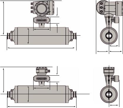
Hygienic versions
1
B1
F
E
A
G
D
H I
2
B2 |
F |
E
A
G
D
Metric (mm) |
|
|
|
|
|
|
|
|
|
|
|
|
|
|
|
|
|
|
||
|
|
|
|
|
|
|
|
|
|
|
|
|
|
|
|
|
|
|
|
|
Meter |
|
|
|
|
|
15 |
|
|
|
|
|
|
|
|
25 |
|
|
|
||
|
|
|
|
|
|
|
|
|
|
|
|
|
|
|
|
|
|
|
|
|
Conn |
|
|
DN25 |
|
|
|
|
1” |
|
|
|
|
DN40 |
|
|
|
|
1½” |
|
|
|
|
|
|
|
|
|
|
|
|
|
|
|
|
|
|
|
|
|
|
|
|
|
DIN 11851 |
DIN 32676 |
DIN 11864-2 |
Tr-Clamp (ISO) |
|
Tri-Clover |
SMS |
IDF |
RJT |
|
DIN 11851 |
DIN 32676 |
DIN 11864-2 |
Tr-Clamp (ISO) |
|
Tri-Clover |
SMS |
IDF |
RJT |
|
|
|
|
|
|
|
|
|
|
|
|
|
|
|
|
|
|
|
||
A |
|
|
|
|
101.6 |
|
|
|
|
|
|
|
114.3 |
|
|
|
||||
|
|
|
|
|
|
|
|
|
|
|
|
|
|
|
|
|
|
|
||
B1 / B2 |
|
|
|
|
311 / 231 |
|
|
|
|
|
|
|
317 / 237 |
|
|
|
||||
|
|
|
|
|
|
|
|
|
|
|
|
|
|
|
|
|
|
|
|
|
D |
|
483 |
468 |
505 |
473 |
|
487 |
474 |
487 |
498 |
|
538 |
515 |
562 |
502 |
|
534 |
537 |
534 |
545 |
|
|
|
|
|
|
|
|
|
|
|
|
|
|
|
|
|
|
|
|
|
|
|
|
|
|
|
40 |
|
|
|
|
|
|
|
|
50 |
|
|
|
||
|
|
|
|
|
|
|
|
|
|
|
|
|
|
|
|
|
|
|
|
|
|
|
|
DN50 |
|
|
|
|
2” |
|
|
|
|
DN80 |
|
|
|
|
3” |
|
|
|
|
|
|
|
|
|
|
|
|
|
|
|
|
|
|
|
|
|
|
|
|
|
DIN 11851 |
DIN 32676 |
DIN 11864-2 |
Tr-Clamp (ISO) |
|
Tri-Clover |
SMS |
IDF |
RJT |
|
DIN 11851 |
DIN 32676 |
DIN 11864-2 |
Tr-Clamp (ISO) |
|
Tri-Clover |
SMS |
IDF |
RJT |
|
|
|
|
|
|
|
|
|
|
|
|
|
|
|
|
|
|
|
||
A |
|
|
|
|
168.3 |
|
|
|
|
|
|
|
219.1 |
|
|
|
||||
|
|
|
|
|
|
|
|
|
|
|
|
|
|
|
|
|
|
|
||
B1 / B2 |
|
|
|
|
344 / 264 |
|
|
|
|
|
|
|
370 / 290 |
|
|
|
||||
|
|
|
|
|
|
|
|
|
|
|
|
|
|
|
|
|
|
|
|
|
D |
|
704 |
677 |
724 |
667 |
|
691 |
694 |
691 |
702 |
|
870 |
836 |
896 |
817 |
|
832 |
837 |
832 |
843 |
|
|
|
|
|
|
|
|
|
|
|
|
|
|
|
|
|
|
|
|
|
All sizes |
|
|
|
|
|
|
|
|
|
|
|
|
|
|
|
|
|
|
|
|
|
|
|
|
|
|
|
|
|
|
|
|
|
|
|
|
|
|
|
|
|
E |
|
|
|
|
|
|
|
|
|
|
160 |
|
|
|
|
|
|
|
|
|
|
|
|
|
|
|
|
|
|
|
|
|
|
|
|
|
|
|
|
|
|
F |
|
|
|
|
|
|
|
|
|
|
60 |
|
|
|
|
|
|
|
|
|
|
|
|
|
|
|
|
|
|
|
|
|
|
|
|
|
|
|
|
|
|
G |
|
|
|
|
|
|
|
|
|
|
98.5 |
|
|
|
|
|
|
|
|
|
|
|
|
|
|
|
|
|
|
|
|
|
|
|
|
|
|
|
|
|
|
H |
|
|
|
|
|
|
|
|
|
123.5 |
|
|
|
|
|
|
|
|
||
|
|
|
|
|
|
|
|
|
|
|
|
|
|
|
|
|
|
|
|
|
I |
|
|
|
|
|
|
|
|
|
|
137 |
|
|
|
|
|
|
|
|
|
|
|
|
|
|
|
|
|
|
|
|
|
|
|
|
|
|
|
|
|
|
22
Imperial (inches) |
|
|
|
|
|
|
|
|
|
|
|
|
|
|
|
|
|
|
|||
|
|
|
|
|
|
|
|
|
|
|
|
|
|
|
|
|
|
|
|
|
|
Meter |
|
|
|
|
|
|
15 |
|
|
|
|
|
|
|
|
25 |
|
|
|
||
|
|
|
|
|
|
|
|
|
|
|
|
|
|
|
|
|
|
|
|
|
|
Conn |
|
|
|
DN25 |
|
|
|
|
1” |
|
|
|
|
DN40 |
|
|
|
|
1½” |
|
|
|
|
|
|
|
|
|
|
|
|
|
|
|
|
|
|
|
|
|
|
|
|
|
|
DIN 11851 |
|
DIN 32676 |
DIN 11864-2 |
Tr-Clamp (ISO) |
|
Tri-Clover |
SMS |
IDF |
RJT |
|
DIN 11851 |
DIN 32676 |
DIN 11864-2 |
Tr-Clamp (ISO) |
|
Tri-Clover |
SMS |
IDF |
RJT |
|
|
|
|
|
|
|
|
|
|
|
|
|
|
|
|
|
|
|
|
|
|
A |
|
|
|
|
|
|
4 |
|
|
|
|
|
|
|
|
4.5 |
|
|
|
||
|
|
|
|
|
|
|
|
|
|
|
|
|
|
|
|
|
|
|
|
||
B1 / B2 |
|
|
|
|
|
12.2 / 9.0 |
|
|
|
|
|
|
|
12.5 / 9.3 |
|
|
|
||||
|
|
|
|
|
|
|
|
|
|
|
|
|
|
|
|
|
|
|
|
|
|
D |
|
19 |
|
18.4 |
19.9 |
18.6 |
|
19.2 |
18.7 |
19.2 |
19.6 |
|
21.2 |
20.3 |
22.1 |
19.8 |
|
21 |
21.1 |
21 |
21.4 |
|
|
|
|
|
|
|
|
|
|
|
|
|
|
|
|
|
|
|
|
|
|
|
|
|
|
|
|
|
40 |
|
|
|
|
|
|
|
|
50 |
|
|
|
||
|
|
|
|
|
|
|
|
|
|
|
|
|
|
|
|
|
|
|
|
|
|
|
|
|
|
DN50 |
|
|
|
|
2” |
|
|
|
|
DN80 |
|
|
|
|
3” |
|
|
|
|
|
|
|
|
|
|
|
|
|
|
|
|
|
|
|
|
|
|
|
|
|
|
DIN 11851 |
|
DIN 32676 |
DIN 11864-2 |
Tr-Clamp (ISO) |
|
Tri-Clover |
SMS |
IDF |
RJT |
|
DIN 11851 |
DIN 32676 |
DIN 11864-2 |
Tr-Clamp (ISO) |
|
Tri-Clover |
SMS |
IDF |
RJT |
|
|
|
|
|
|
|
|
|
|
|
|
|
|
|
|
|
|
|
|
|
|
A |
|
|
|
|
|
|
6.6 |
|
|
|
|
|
|
|
|
8.6 |
|
|
|
||
|
|
|
|
|
|
|
|
|
|
|
|
|
|
|
|
|
|
|
|
||
B1 / B2 |
|
|
|
|
|
13.5 / 10.4 |
|
|
|
|
|
|
|
14.6 / 11.4 |
|
|
|
||||
|
|
|
|
|
|
|
|
|
|
|
|
|
|
|
|
|
|
|
|
|
|
D |
|
27.7 |
|
26.6 |
28.5 |
26.2 |
|
27.2 |
27.3 |
27.2 |
27.6 |
|
34.2 |
32.9 |
35.3 |
32.2 |
|
32.7 |
32.9 |
32.7 |
33.2 |
|
|
|
|
|
|
|
|
|
|
|
|
|
|
|
|
|
|
|
|
|
|
All sizes |
|
|
|
|
|
|
|
|
|
|
|
|
|
|
|
|
|
|
|
|
|
|
|
|
|
|
|
|
|
|
|
|
|
|
|
|
|
|
|
|
|
|
|
E |
|
|
|
|
|
|
|
|
|
|
|
6.3 |
|
|
|
|
|
|
|
|
|
|
|
|
|
|
|
|
|
|
|
|
|
|
|
|
|
|
|
|
|
|
|
F |
|
|
|
|
|
|
|
|
|
|
|
2.4 |
|
|
|
|
|
|
|
|
|
|
|
|
|
|
|
|
|
|
|
|
|
|
|
|
|
|
|
|
|
|
|
G |
|
|
|
|
|
|
|
|
|
|
|
3.9 |
|
|
|
|
|
|
|
|
|
|
|
|
|
|
|
|
|
|
|
|
|
|
|
|
|
|
|
|
|
|
|
H |
|
|
|
|
|
|
|
|
|
|
|
4.9 |
|
|
|
|
|
|
|
|
|
|
|
|
|
|
|
|
|
|
|
|
|
|
|
|
|
|
|
|
|
|
|
I |
|
|
|
|
|
|
|
|
|
|
|
5.4 |
|
|
|
|
|
|
|
|
|
|
|
|
|
|
|
|
|
|
|
|
|
|
|
|
|
|
|
|
|
|
|
23
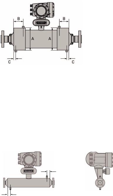
Heating Jacket
Meter size |
DN15 |
DN25 |
DN40 |
DN50 |
|
|
|
|
|
Connection size |
|
½” (12mm) |
|
1” (25mm) |
|
|
|
|
|
Metric (mm) |
|
|
|
|
|
|
|
|
|
A |
115 ±1.0 |
142 ±1.0 |
206 ±1.0 |
254 ±1.0 |
|
|
|
|
|
B |
51 |
55 |
90 |
105 |
|
|
|
|
|
C |
|
20 |
|
26 |
|
|
|
|
|
Imperial (inches) |
|
|
|
|
|
|
|
|
|
A |
4.5 ±0.04 |
5.6 ±0.04 |
8.1 ±0.04 |
10.0 ±0.04 |
|
|
|
|
|
B |
2.0 |
2.2 |
3.5 |
4.1 |
|
|
|
|
|
C |
|
0.8 |
|
1.0 |
|
|
|
|
|
Purge Port
B
A
Meter size |
DN15 |
|
DN25 |
DN40 |
|
DN50 |
|
|
|
|
|
|
|
Metric (mm) |
|
|
|
|
|
|
|
|
|
|
|
|
|
A |
30 ±1.0 |
|
|
65 ±1.0 |
||
|
|
|
|
|
|
|
B |
30 ±1.0 |
|
|
65 ±1.0 |
||
|
|
|
|
|
|
|
Imperial (inches) |
|
|
|
|
|
|
|
|
|
|
|
|
|
A |
1.2 ±0.04 |
|
|
2.5 ±0.04 |
||
|
|
|
|
|
|
|
B |
1.2 ±0.04 |
|
|
2.5 ±0.04 |
||
|
|
|
|
|
|
|
24

5 |
OPTIMASS 2000 |
OPTIMASS |
|
|
|
5.1 Specific Installation Guidelines
•Tighten flange bolts evenly.
•Observe the pipe end loads as shown in S.5.6
•It is permissible to support the weight of the meter on the body.
•Use of standard pipework reducers at the flange is allowed. Avoid extreme changes in pipe size (step changes).
•The use of flexible hoses for connection to the process pipework is NOT recommended.
•The meter can be installed so that the converter is on the side of the meter, resulting in the measuring tubes on top of each other, unless gases or solids are being measured.
•The 2000 series has exceptional immunity to cross-talk, therefore allowing meters to be used in series or parallel
5.2 Ambient / Process temperatures
The specified and approved ambient and process temperatures must be observed.
|
|
|
SS318L |
|
||
|
|
|
|
|||
|
|
°C |
°F |
|||
|
|
|
|
|
||
Process |
All meters |
-45... |
+130 |
-49... |
266 |
|
|
|
|
|
|
|
|
|
Compact Al. |
-40... |
+60 |
40... |
+140 |
|
|
|
|
|
|
|
|
Ambient |
Compact Al. with certain I/O options (consult Krohne) |
-40... |
+65 |
-40... |
+149 |
|
|
|
|
|
|
||
Compact SS |
-40 |
+55 |
-40 |
+131 |
||
|
||||||
|
|
|
|
|
|
|
|
Remote |
-40... |
+65 |
-40... |
+149 |
|
|
|
|
|
|
|
|
Note:
For additional temperature limits in hazardous area applications, reference should be made to the publication “Guidelines for the use of Coriolis Meters in Hazardous Areas”.
Where meters are mounted in direct sunlight, it is recommended to install a sunshade that covers the converter and front end. This is particularly important in countries with high ambient temperatures.
The maximum differential temperature between the process and ambient temperature without insulation is 110°C or 200°F.
To avoid thermal shock, the meter MUST NOT be subject to rapid changes in process tempratures and reference should be made to the following table
Meter |
Max. Temperature Shift |
|
|
S100 |
90°C (110°C with a max operating pressure of 40 barg) |
|
|
S150 |
80°C |
|
|
S250 |
50°C |
|
|
Operation outside these limits may result in shifts in density and mass flow calibration. Repeated shocking may also lead to premature failure of the meter! However, higher thermal shocks are possible at lower working presures. Please consult Krohne for more information.
5.3 Pressure Equipment Directive (PED) requirements
To comply with the requirements of the PED in Europe, the following information is provided to assist the plant engineer in installing the meter:
Measuring tube: |
Spigots |
|
|
Stainless Steel UNS 531803 |
Stainless Steel UNS J902205 |
|
|
The outer cylinder 304 / 304L is dual certified (Optional outer cylinder of 316 / 316L).
Wiring feedthrough is made of Epoxy (or PEEK) with 2 ‘O’ ring seals in Fpm / fkm & Hydrogenated Nitrile.
25
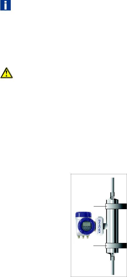
Flanges:
PN160/250 and ASME 900/1500 are duplex stainless steel (UNS 531803). All other flanges are 316 / 316 L dual certified (optional UNS 531803).
NOTE: if the NACE option has been selected at the time of order, the flanges will be duplex stainless steel (UNS 31803).
Hygienic Connections are 316L (S100 only)
Optional heating jacket 316 / 316L
Note: Outer cylinder is in contact with heating medium
5.4 Secondary Pressure containment
The OPTIMASS 2000 meters are supplied (as standard) without certified housings that have a typical burst pressure >100 barg.
If the user suspects that the primary tube has failed, the unit must be depressurised and removed from service as soon as it is safe to do so.
Note:
In the 2000 Series there is a high pressure wire feed through with ‘O’ rings that might not be compatible with the process fluid for an extended period if a primary tube fails.
It is the user’s responsibility to ensure that the materials used are compatible with this product.
Other ‘O’ ring materials are available on request.
5.5 Hygienic Applications
The OPTIMASS 2000 (S100) is available with a variety of hygienic process connectors.
When installing / using meters with hygienic process connectors, support /clamp the meter properly. The meters are heavy and could injure when disconnected from the adjacent pipe work.
The recommended method of installation is to mount the meter against a support / wall with the body of the meter supported / clamped. The process pipe work can then be supported off the meter. The meter is too heavy to be supported from the thin walled piping usually associated with the hygienic industry. For information regarding lifting the meter, please refer to section 3.4.
1
2
1 2 Meter Supports
26

The 3A approval for the 2000 series requires that it is “self draining”. Therefore, the meter MUST be installed vertically with the flow running uphill.
Installation lengths
For installation lengths, please see section 5.9
Please check with KROHNE if you are unsure of the installation length. Many meters are built to customer requirements / specifications especially where special hygienic process nectors have been adapted to the meter. As these are normally non-standard, the installation length will not be given in the technical data.
5.6 Pressure Ratings
Measuring Tube PED certification
Measuring Tube FM certification |
See pressure de-rating graphs |
Measuring Tube CRN & CSA certification
Meter data plates are stamped with maximum pressure rating at both 20°C (68°F) and maximum operating temperature of connection or primary tube, whichever is the lower.
Maximum pipe work forces
size |
|
20°C |
|
130°C |
||
|
|
|
|
|
|
|
|
40 barg |
100 barg |
150 barg |
32 bar |
80 barg |
115 barg |
|
|
|
|
|
|
|
100 |
150 kN |
100 kN |
150 kN |
60 kN |
||
|
|
|
|
|
||
150 |
650 kN |
120 kN |
280 kN |
50 kN |
||
|
|
|
|
|
||
250 |
550 kN |
60 kN |
400 kN |
50 kN |
||
|
|
|
|
|
|
|
|
|
|
|
|
|
|
Flange Connections |
|
|
|
|
|
|
|
|
|
|
|
|
|
These loads are roughly equivalent to the max axial loading allowed in an un-radiographed butt weld in a 316L schedule 80 pipe.
Loads given maximum static loads. If loads are cycling, particularly between tension and compression then these loads should be reduced.
Please consult KROHNE for more information.
27
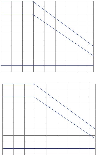
Pressure de-rating
P (bar)150 |
|
|
|
|
|
|
|
|
145 |
|
|
|
|
|
|
|
|
140 |
|
|
|
|
|
|
|
|
135 |
|
|
|
|
|
|
|
|
130 |
|
|
|
|
|
|
|
|
125 |
|
|
|
|
|
|
|
|
120 |
|
|
|
|
|
|
|
|
115 |
|
|
|
|
|
|
|
1 |
110 |
|
|
|
|
|
|
|
|
105 |
|
|
|
|
|
|
|
2 |
|
|
|
|
|
|
|
|
|
100 |
|
|
|
|
|
|
|
3 |
0 |
|
|
|
|
|
|
|
|
-40 |
-20 |
0 |
20 |
40 |
60 |
80 |
100 |
120 130 |
P (psi) 2176 |
|
|
|
|
|
|
|
|
2103 |
|
|
|
|
|
|
|
|
2030 |
|
|
|
|
|
|
|
|
1958 |
|
|
|
|
|
|
|
|
1885 |
|
|
|
|
|
|
|
|
1813 |
|
|
|
|
|
|
|
|
1740 |
|
|
|
|
|
|
|
|
1668 |
|
|
|
|
|
|
|
1 |
1595 |
|
|
|
|
|
|
|
|
1523 |
|
|
|
|
|
|
|
2 |
|
|
|
|
|
|
|
|
|
1450 |
|
|
|
|
|
|
|
3 |
0 |
|
|
|
|
|
|
|
|
-40 |
-4 |
32 |
68 |
104 |
140 |
176 |
212 |
248 266 |
|
|
|
|
T OF |
|
|
|
|
1 Measuring Tube PED certification
2 Measuring Tube FM certification
3 Measuring Tube CRN & CSA certification Flanges
DIN flange ratings based on EN 1092-1 2007 table G.4.1 material group 14E0 ASME flange ratings based on ASME B16.5 2003 table 2 material group 2.2
JIS flange ratings based on JIS 2220: 2001 table 1 division 1 material group 022a Note:
The maximum operating pressure will be either the flange rating or measuring tube rating WHICHEVER IS THE LOWER!
It is recommended that the seals be replaced regularly to maintain the hygienic integrity of the connection.
28
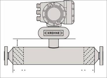
Unless specifically requested, internal surfaces are not polished and no warranty is made as to the surface finish.
If polishing option and /or EHEDG, ASME Bio-Processing or 3A approvals was selected at time of order, all product contact surfaces are polished 0.5 micrometer Ra (20CLa) finish or better.
5.7 Heating and insulation
There are several ways to heat the meter. In most cases heating is unnecessary as the meter is designed so that very little heat is lost or gained through the outer cylinder.
Insulation
Where insulation is required, a variety of materials may be used to insulate the meter. Care must be taken not to insulate the meter above the halfway mark of the electronics support post as shown.
Electrical Heating
Electrical tape heating may be used. Care should be taken to only heat the sections where the best effect will be achieved. Do not heat above the converter mount centre line as shown above.
The following guidelines must be observed.
1
|
|
|
|
|
|
|
|
|
2 |
|
|
3 |
|
|
|
2 |
|
|
|
|||||||
1 Max insulation depth
2 Heated Areas
3 Do NOT heat this area
When insulating please observe guidelines as per insulation section.
Size |
DIM 1 |
|
|
100 |
200 mm |
|
|
150 |
250 mm |
|
|
250 |
250 mm |
|
|
29
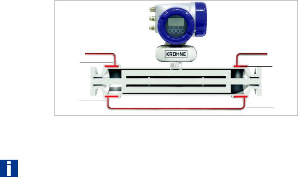
Liquid / Steam heating jacket
The meter can be supplied with a heating jacket. This jacket is designed to minimise the differential stress across the meter where differences in temperature between outer cylinder and measuring tube exist.
The connections to the heating jacket are NPT or Ermeto sockets.
It is recommended that reinforced flexible hoses be used to connect the heating jacket to the heat source.
1 |
2 |
|
3 |
4 |
|
1 2 3 4 Connection Points
Important:
Always heat the jacket to working temperature before flowing product in measuring tube.
Avoid the use of fluids that can cause crevice corrosion.
Although all the jacket materials are 316L, the outer cylinders are 304L (Optional 316L).
Connections should be made to ensure all air can be vented on liquid systems and all condensate can be drained on steam systems.
Note :
Max heating medium pressure and temperature for heating jackets is 10 bar at 130°C or 145 psig at 266°F.
Heating Times
The heating times shown in the following illustrations are based on the heating jacket operating at maximum temperature and show the measured temperatures at the spigot end of the measuring tubes. If a desired temperature is required in the centre of the measuring tubes, then the heating times MUST be extended.
30
 Loading...