


Tank Level Monitoring System
Operator’s manual
Rev. 1.08
May 2004
CARGOMASTER® 5

CARGOMASTER®5
Contact information
KROHNE Skarpenord
Strømtangvn. 21
N-3950 Brevik
NORWAY
Telephone: +47 3556 1220
FAX: +47 3556 1221
E-mail: ksl@krohne.no
Operators Manual - 2

CARGOMASTER®5
Contents |
|
|
1. |
Introduction........................................................................................... |
6 |
|
A brief system overview ................................................................................................................ |
7 |
|
Mechanical/Electrical............................................................................................................. |
7 |
|
Computer program.................................................................................................................. |
9 |
|
Help system ........................................................................................................................... |
10 |
|
Precautions ................................................................................................................................... |
10 |
2. |
Basics .................................................................................................. |
11 |
|
Login/logout................................................................................................................................. |
11 |
|
Navigation .................................................................................................................................... |
11 |
|
Keyboard ............................................................................................................................... |
11 |
|
Mouse / Trackball ................................................................................................................. |
11 |
|
Selecting view........................................................................................................................ |
12 |
|
Quick Start.................................................................................................................................... |
13 |
|
Step 1 – Check status ............................................................................................................ |
13 |
|
Step 2 – Activating online mode ........................................................................................... |
13 |
|
Step 3 – Select tanks to view ................................................................................................. |
13 |
|
Step 4 - Select your preferred View ...................................................................................... |
14 |
3. |
A Planning Example ........................................................................... |
15 |
|
Online or Planning mode?.................................................................................................... |
16 |
|
Creating a new planning condition.............................................................................................. |
16 |
|
Prepare for loading....................................................................................................................... |
17 |
|
Define Group......................................................................................................................... |
17 |
|
Select tanks............................................................................................................................ |
18 |
|
Density settings ..................................................................................................................... |
19 |
|
Alarm settings........................................................................................................................ |
19 |
|
Zero adjust – sensor optimization......................................................................................... |
20 |
|
Bringing the new condition online........................................................................................ |
20 |
4. |
Reference ............................................................................................ |
22 |
|
Groups .......................................................................................................................................... |
22 |
|
Group modes ......................................................................................................................... |
22 |
|
Setting up a new group.......................................................................................................... |
23 |
|
Edit existing group ................................................................................................................ |
24 |
|
Add or remove tanks in groups ............................................................................................. |
24 |
|
Density settings ..................................................................................................................... |
25 |
|
Alarm Settings ....................................................................................................................... |
26 |
|
Zero adjustment..................................................................................................................... |
26 |
|
Finish Time calculations.............................................................................................................. |
27 |
|
Partial load or discharge operations............................................................................................. |
27 |
|
Scratch groups.............................................................................................................................. |
29 |
|
Partial sums........................................................................................................................... |
29 |
|
Handle Alarms ............................................................................................................................. |
30 |
|
Acknowledge - Silence .......................................................................................................... |
30 |
|
Overview................................................................................................................................ |
30 |
|
ValueTable info ..................................................................................................................... |
31 |
|
Adjust alarm limits ................................................................................................................ |
31 |
|
Alarms on - off....................................................................................................................... |
32 |
|
Available Alarm Types .......................................................................................................... |
32 |
|
Online Window...................................................................................................................... |
33 |
|
Alarms in network ................................................................................................................. |
34 |
|
Alarm master/slave ............................................................................................................... |
35 |
3 - Operators Manual

CARGOMASTER®5
|
Zero adjustments .......................................................................................................................... |
36 |
|
Tank pressure sensors........................................................................................................... |
36 |
|
Line sensors........................................................................................................................... |
36 |
|
Vapor sensors........................................................................................................................ |
36 |
|
Hints for successful zero setting ........................................................................................... |
37 |
|
Krohne BM70 radar.............................................................................................................. |
37 |
|
Reports.......................................................................................................................................... |
38 |
|
Loadcalc ....................................................................................................................................... |
39 |
|
Stability Results..................................................................................................................... |
40 |
|
Hull Stress ............................................................................................................................. |
41 |
|
GMT / local time.......................................................................................................................... |
42 |
|
Trim – List - Draft........................................................................................................................ |
43 |
|
Adjusting................................................................................................................................ |
44 |
|
Handle conditions ........................................................................................................................ |
45 |
|
Condition Manager ............................................................................................................... |
45 |
|
Online Condition................................................................................................................... |
45 |
|
Planning ................................................................................................................................ |
46 |
|
Tankplan....................................................................................................................................... |
46 |
|
Show tank or group details ................................................................................................... |
46 |
|
Adjusting the view ................................................................................................................. |
47 |
|
Group Information ................................................................................................................ |
47 |
|
Tank Information................................................................................................................... |
48 |
|
Valuetable..................................................................................................................................... |
51 |
|
Adjusting the view ................................................................................................................. |
51 |
|
Add or remove tanks from view ............................................................................................ |
52 |
|
Change column content......................................................................................................... |
52 |
|
View a different group........................................................................................................... |
53 |
|
Select layer ............................................................................................................................ |
53 |
|
The Sum field......................................................................................................................... |
54 |
|
Keyboard shortcuts for ValueTable...................................................................................... |
54 |
|
Valuetable codes ................................................................................................................... |
54 |
|
Bargraphs ..................................................................................................................................... |
55 |
|
Change Value Type ............................................................................................................... |
55 |
|
Right-click Options ............................................................................................................... |
55 |
|
Adjust fontsize ....................................................................................................................... |
55 |
|
Line/Vapors.................................................................................................................................. |
56 |
|
Keyboard shortcuts ...................................................................................................................... |
56 |
|
Normal shortcuts................................................................................................................... |
57 |
|
Special shortcuts: .................................................................................................................. |
57 |
|
Keyboard shortcuts for Valuetable....................................................................................... |
58 |
|
Density variables.......................................................................................................................... |
58 |
|
Units ............................................................................................................................................. |
59 |
|
Preferences ................................................................................................................................... |
60 |
|
Pictures tab ........................................................................................................................... |
60 |
|
Calculations tab:................................................................................................................... |
61 |
|
Fonts tab................................................................................................................................ |
62 |
|
Terminal support (VT100)........................................................................................................... |
62 |
|
How to use............................................................................................................................. |
62 |
5. |
Maintenance........................................................................................ |
64 |
|
Sensor disable............................................................................................................................... |
64 |
|
Backup – restore........................................................................................................................... |
64 |
|
Backup ................................................................................................................................... |
64 |
|
Export of Logger Data .......................................................................................................... |
65 |
|
Export of System Logs........................................................................................................... |
65 |
|
Restore All ............................................................................................................................. |
65 |
|
Restore User Data Only........................................................................................................ |
66 |
|
Replace sensor.............................................................................................................................. |
66 |
|
Replacement procedure ........................................................................................................ |
66 |
Operators Manual - 4

CARGOMASTER®5
Offset and gain adjustments......................................................................................................... |
68 |
|
|
Offset adjustment................................................................................................................... |
68 |
|
Gain adjustment .................................................................................................................... |
70 |
Level from bottom and upper sensors. ........................................................................................ |
71 |
|
|
Redundancy for Ballast tanks. .............................................................................................. |
71 |
Appendix........................................................................................................ |
73 |
|
A. |
Tank names conversion..................................................................................................... |
73 |
B. |
Loadcalc Stability Criteria ................................................................................................ |
73 |
C. |
Note on free surfaces......................................................................................................... |
73 |
D. |
Gas/LPG Tanker Units ...................................................................................................... |
74 |
|
Description of units............................................................................................................... |
74 |
E. |
Ground insulation monitor for Radar power..................................................................... |
76 |
5 - Operators Manual

CARGOMASTER®5
1. Introduction
This manual covers the use of the CARGOMASTER® computer and its software portion. You will, however, find a few important notes on maintenance and precautions regarding the mechanical and electrical installations. New users are encouraged to read the “Basics” section carefully.
The CARGOMASTER® software, or computer program, is designed to utilize groups and conditions. This means organizing your tanks (or grades) into groups for more convenient handling of densities, alarm settings etc. Furthermore, your different groups setup may be saved and retrieved as conditions. This opens for planning a voyage in advance, and reuse of frequently used tank/cargo allocations. These issues are discussed further in the Basics section.
The examples throughout this manual are gathered from M/T SKARPEFJORD, a highly hypothetical vessel designed to include most common configuration options available. Your vessel will probably look somewhat different, but the procedures and the way to work the program will be representative for most installations.
Operators Manual - 6

CARGOMASTER®5
A brief system overview
Mechanical/Electrical
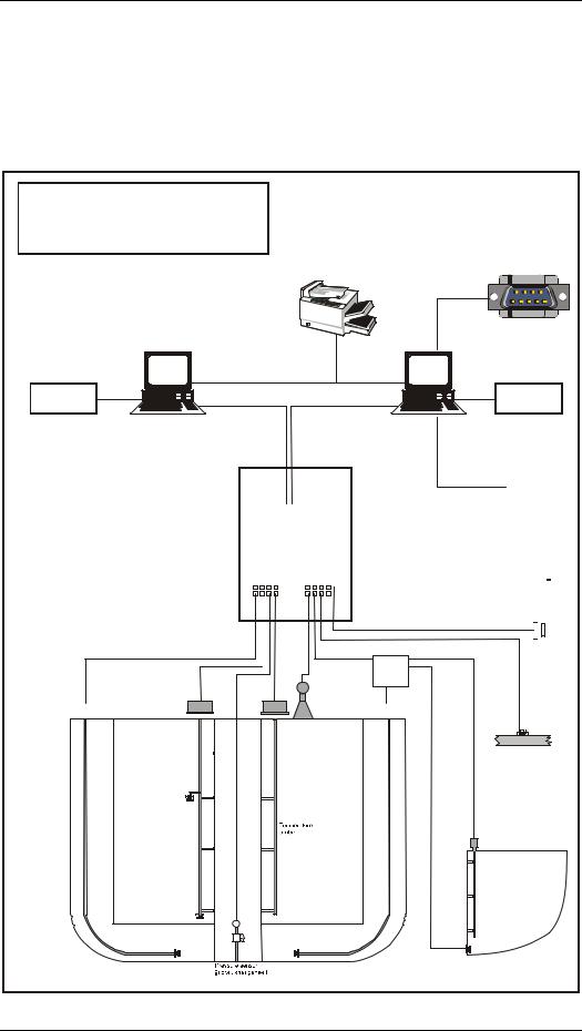
A complete CARGOMASTER® system includes quite a few components. There are both mechanical and electrical parts, as well as computer programs involved in the process of monitoring the various tanks on your vessel. (See Fig. 1) presents the most common parts of such a system, and indicates a few different options. CARGOMASTER® is a modular system so all these options may not be configured and installed on your vessel.
A few words on some of the various system parts:
CCU: |
Short for CARGOMASTER® Computer Unit. |
|
Ordinary PC type computers, however configured and |
|
type approved for maritime use. Normally, these |
|
computers are powered via an UPS – Uninterruptable |
|
Power Supply. A laser printer is also handy, and is |
|
needed in order to get printed reports. In order to |
|
retrieve gauging data, the CCU needs to be connected |
|
to the |
SCU: |
Short for Signal Control Unit. This is where all data is |
|
collected from the various transmitters or gauges and |
|
forwarded to the CCU. |
Other systems: |
CARGOMASTER® supports an array of protocols to |
|
communicate with other vessel systems, usually trough |
|
a RS232 or 485 serial interface. |
Gauges: |
CARGOMASTER® can utilize a variety of |
|
sensors/transmitters, primarily the native |
|
CARGOMASTER® types. The range includes |
|
ballast/line pressure sensors, the combined |
|
pressure/temperature cargo sensors, radar transmitters, |
|
various temperature transmitters, and various 4-20mA |
|
transmitters. CARGOMASTER® can also retrieve |
|
data from 3rd party systems. |
Junction boxes: |
Some of the CARGOMASTER® junction boxes, |
|
normally the ones fitted on cargo tanks, host electronic |
|
equipment like AD cards. The boxes are designed to |
|
withstand rough weather conditions, and should not be |
|
opened except for required servicing. Also boxes |
|
placed inside trunks, engine room etc. may have |
|
electronics inside. Please consult the electrical |
|
drawings for the system installed on your vessel for |
|
further details. |
AD/TI/RI cards:
The Analogue/Digital cards, commonly placed in the various junction boxes, converts analogue signals from the cargo and ballast sensors into digital data and
7 - Operators Manual
CARGOMASTER®5
transmits these to the TI (Tank Input) cards placed inside the SCU. The TI card receives the data, and feeds them trough Zener-barriers, necessary for safe electrical connection between Safe and Hazardous areas. Radar transmitters have their own interface card
– the RI (Radar Interface), specially designed for this purpose.
CARGOMASTER®5
System overview
|
Printer |
|
Other systems |
Computer network |
|
UPS |
UPS |
CCU 2 (optional) |
CCU1 |
SCU |
|
|
|
|
|
|
|
|
|
|
|
|
|
|
|
|
|
|
|
|
|
|
|
|
|
|
|
|
|
|
|
|
|
|
|
|
|
|
|
|
|
|
|
|
|
|
|
|
|
|
|
|
|
|
|
|
|
|
|
|
|
|
|
|
|
|
|
|
|
|
|
|
|
|
|
|
|
|
|
|
|
|
|
|
|
|
|
|
|
|
|
|
|
|
|
|
|
|
|
|
|
|
|
|
|
|
|
|
|
|
|
|
|
|
|
|
|
|
|
|
|
|
|
|
|
|
|
|
|
|
|
|
|
|
|
|
|
|
|
|
|
|
|
|
|
|
|
|
|
|
|
|
|
|
|
|
|
|
|
|
|
|
|
|
|
|
|
|
|
|
|
|
|
|
|
|
|
|
|
|
|
|
|
|
|
|
|
|
|
|
|
|
|
|
|
|
|
|
|
|
|
|
|
|
|
|
|
|
|
|
|
|
|
|
|
|
|
|
|
|
|
|
|
|
|
|
|
|
|
|
|
|
|
|
|
|
|
|
|
|
|
|
|
|
|
|
|
|
|
|
|
|
|
|
|
|
|
|
|
|
|
|
|
|
|
|
|
|
1234 |
|
|||||||||||||||||||||||
|
|
|
|
|
|
|
|
|
|
|
|
|
|
|
|
|
|
|
|
|
|
|
|
|
|
|
|
|
|
|
card |
|
|
|
|
|
card |
|
|
|
|
|
|
|
|
|
|
|
|
|
|
|
|
|
|
|
Meters,horns, |
|||||||||||||||
Safe area |
|
|
|
|
|
|
|
|
|
|
|
|
|
|
|
|
|
|
|
|
Tank input |
|
|
|
|
|
Tank input |
|
|
|
|
|
|
|
|
|
|
|
|
|
|
|
|
|
|
|
displays etc. |
|||||||||||||||||||||||||
|
|
|
|
|
|
|
|
|
|
|
|
|
|
|
|
|
|
|
|
|
|
|
|
|
|
|
|
|
|
|
|
|
|
|
|
|
|
|
|
|
|
|
|
|
|
|
|
|
|
|
|
|||||||||||||||||||||
|
|
|
|
|
|
|
|
|
|
|
|
|
|
|
|
|
|
|
|
|
|
|
|
|
|
|
|
|
|
|
|
|
|
|
|
|
|
|
|
|
|
|
|
|
|
|
|
|
|
|
|
|
|
|
|
|
|
|
|
|
|
|
|
|
|
|
|
|
|
|
|
|
Hazardous |
|
|
|
|
|
|
|
|
|
|
|
|
|
|
|
|
|
|
|
|
|
|
|
|
|
|
|
|
|
|
|
|
|
|
|
|
|
|
|
|
|
|
|
|
|
|
|
|
|
|
|
|
|
|
Atmospheric |
|||||||||||||||||
|
|
|
|
|
|
|
|
|
|
|
|
|
|
|
|
|
|
|
|
|
|
|
|
|
|
|
|
|
|
|
|
|
|
|
|
|
|
|
|
|
|
|
|
|
|
|
|
|
|
|
|
|
|
|||||||||||||||||||
area |
|
|
|
|
|
|
|
|
|
|
|
|
|
|
|
|
|
|
|
|
|
|
|
|
|
|
|
|
|
|
|
|
|
|
|
|
|
|
|
|
|
|
|
|
|
|
|
|
|
|
|
|
|
|
||||||||||||||||||
|
|
|
|
|
|
|
|
|
|
|
|
|
|
|
|
|
|
|
|
|
|
|
|
|
|
|
|
|
|
|
|
|
|
|
|
|
|
|
|
|
|
|
|
|
|
|
|
|
|
|
|
|
|
reference sensor |
||||||||||||||||||
|
|
|
|
|
|
|
|
|
|
|
|
|
|
|
|
|
|
|
|
|
|
|
|
|
|
|
|
|
|
|
|
|
|
|
|
|
|
|
|
|
|
|
|
|
|
|
|
|
|
|
|
|
|
|
|
|
|
|
|
|
|
|
|
|
and inclinometers |
|||||||
|
|
|
|
|
|
|
|
|
|
|
|
|
|
|
|
|
|
|
|
|
|
|
|
|
|
|
|
|
|
|
|
|
|
|
|
|
|
|
|
|
|
|
|
|
|
|
|
|
|
|
|
|
|
|
|
|
|
|
|
|
|
|
|
|
|
|
|
|
|
|
|
|
|
|
|
Junction box |
|
|
|
|
Junction box |
|
|
|
|
|
|
|
|
|
|
|
|
|
|
|
Multi-tank |
||||||||||||||||||||||||||||||||||||||||||||||||
|
|
|
|
|
|
|
|
|
|
|
|
|
|
|
|
|
|
|
|
|
|
junction box |
||||||||||||||||||||||||||||||||||||||||||||||||||
|
|
|
for ballast tank |
|
|
|
|
for cargo tank. |
|
|
|
|
|
|
|
|
|
|
|
|
|
|
w/ AD card |
|||||||||||||||||||||||||||||||||||||||||||||||||
|
|
|
|
|
|
|
|
|
|
|
|
|
|
|
AD card and |
|
|
|
|
|
|
|
|
|
|
|
|
|
|
|
|
|
|
|
|
|
|
|
|
|
|
|
|
|
|
|
|
|
|
|
|
|
|
|||||||||||||||||||
|
|
|
|
|
|
|
|
|
|
|
|
|
|
|
inert pressure sensor |
|
|
|
|
|
Radar |
|
|
|
|
|
|
|
|
|
|
|
|
|
|
|
|
|
|
|
|
|
|
|
|
|
|
|||||||||||||||||||||||||
|
|
|
|
|
|
|
|
|
|
|
|
|
|
|
inside |
|
|
|
|
|
for cargo tank |
|
|
|
|
|
|
|
|
|
|
|
|
|
|
|
|
|
|
|
|
|
|
|
|
|
|
|||||||||||||||||||||||||
|
|
|
|
|
|
|
|
|
|
|
|
|
|
|
|
|
|
|
|
|
|
|
|
|
|
|
|
|
|
|
|
|
|
|
|
|
|
|
|
|
|
|
|
|
|
|
|
|
|
|
|
|
|
|
|
|||||||||||||||||
|
|
|
|
|
|
|
|
|
|
|
|
|
|
|
|
|
|
|
|
|
|
|
|
|
|
|
|
|
|
|
|
|
|
|
|
|
|
|
|
|
|
|
|
|
|
|
|
|
|
|
|
|
|
|
|
|
|
|
|
|
|
|
|
|
|
|
|
|
|
|
|
|
|
|
|
|
|
|
|
|
|
|
|
|
|
|
|
|
|
|
|
|
|
|
|
|
|
|
|
|
|
|
|
|
|
|
|
|
|
|
|
|
|
|
|
|
|
|
|
|
|
|
|
|
|
|
|
|
|
|
|
|
|
|
|
|
|
|
|
|
|
|
|
|
|
|
|
|
|
|
|
|
|
|
|
|
|
Combined |
|
|
|
|
|
|
|
|
|
|
|
|
|
|
|
|
|
|
|
|
|
|
|
|
|
|
|
|
|
|
|
|
|
|
|
|
|
|
||||||||||||||||||||||
|
|
|
|
|
|
|
|
|
|
|
|
|
|
|
|
|
|
|
|
|
|
|
|
|
|
|
|
|
|
|
|
|
|
|
|
|
|
|
|
|
|
|
|
|
|
|
|
|
|
|
|
|
|
|
Line and pump |
|||||||||||||||||
|
|
|
|
|
|
|
|
|
|
|
|
pressure and |
|
|
|
|
|
|
|
|
|
|
|
|
|
|
|
|
|
|
|
|
|
|
|
|
|
|
|
|
|
|
|
|
|
|
|
|
|
|
|
|
|
|
|
pressures |
||||||||||||||||
|
|
|
|
|
|
|
|
|
|
|
|
temperature |
|
|
|
|
|
|
|
|
|
|
|
|
|
|
|
|
|
|
|
|
|
|
|
|
|
|
|
|
|
|
|
|
|
|
|
|
|
|
||||||||||||||||||||||
|
|
|
|
|
|
|
|
|
|
|
|
sensors in cargo tank |
|
|
|
|
|
|
|
|
|
|
|
|
|
|
|
|
|
|
|
|
|
|
|
|
|
|
|
|
|
|
|
|
|
|
|
|
|
|
||||||||||||||||||||||
|
|
|
|
|
|
|
|
|
|
|
|
|
|
|
|
|
|
|
|
|
|
|
|
|
|
|
|
|
|
|
|
|
|
|
|
|
|
|
|
|
|
|
|
|
|
|
|
|
|
|
|
|
|
|
|
|
|
|
|
|
|
|
|
|
|
|
|
|
|
|
|
|
Fuel, service and misc tanks
Optional temperature probing
Pressure sensor
in ballast tank Pressure sensor
Fig. 1 Cargomaster connections
Operators Manual - 8
CARGOMASTER®5
Computer program
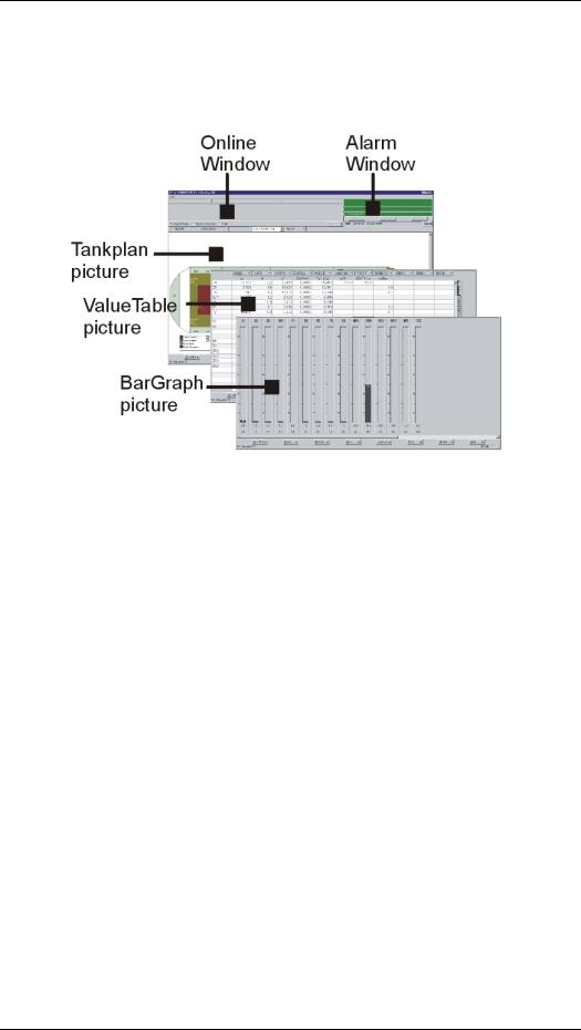
Screenshot 1 Screen layout for the CARGOMASTER program.
Online window: Displays important online data from the tanks, even when working on planning conditions.
Alarm window: Green background when no active alarms, red background whenever any active or non-acknowledged alarms
Pictures: Numerical or graphical presentation of data
9 - Operators Manual

CARGOMASTER®5
Help system
CARGOMASTER® provides an online Help system, containing most of the text found in this manual. The help system is contexts sensitive, aiming at providing help on the specific issue you are working on.
Accessing: You can access the help system from anywhere within the CARGOMASTER® program - just press the F1 button.
Help Index: Use the Index tab to search topics
Search: Use the Search tab to search single words, phrases or abbreviations
Favorites: You can add to the Favorites tab any page in the help system. This is convenient for quick access to frequently viewed pages.
Printing: Clicking the printer symbol will print the page you are currently viewing (Or you can right-click the page with the mouse and select the print option there...)
Precautions
Although the mechanical and electrical parts of CARGOMASTER® are virtually free of maintenance, they are vulnerable to certain physical impacts. So, even though it may seem obviousplease
•Do NOT expose gauges to sandblasting!
•Do NOT overpaint gauges!
•Please take care when cleaning tanks – even small strokes or impacts on the sensor diaphragms may alter the sensors characteristics in such a way that it will become unusable!
•Do NOT replace any seals, o-rings or gaskets with parts that are not clearly specified for this equipment!
Operators Manual - 10
CARGOMASTER®5
2. Basics
Login/logout
To log in on a CARGOMASTER® computer, use the username CMV5 without any password.
If you receive messages that say something like “You don’t have the right privileges....” you might need to log in as username administrator. In this case you must use the password ntconf1
We strongly recommend the CARGOMASTER® program being run under the CMV5 user.
A CARGOMASTER® computer is designed to be running 24 hours a day – 7 days a week
Navigation
Keyboard
Using the keyboard is the fastest way to navigate the CARGOMASTER® program, utilizing the keyboard shortcuts built into the program. The keyboard shortcuts are listed in the Reference chapter.
All menu buttons that have an underscored letter are accessed by pressing that letter simultaneously with the Alt key. E.g. the Condition menu is accessed by pressing and holding the Alt key, then press and release the C key.
Mouse / Trackball
All items are accessible from mouse or trackball. Note that in this online help click refers to clicking the left mouse /trackball button once. Right-click means clicking the right mouse button once. Double-click means clicking the left button twice, rather rapidly. The speed at which a double-click must be done is an adjustable feature within Microsoft Windows; See the MS Windows documentation for further information.
Right clicking will in most cases bring up a context-menu, which will be specific to the item that was clicked.
11 - Operators Manual

CARGOMASTER®5
Selecting view
CARGOMASTER® offers three different ways to view data. They are accessed either by keyboard shortcuts, or by selecting the Pictures button in the bottom of the screen. Select one of the following:
TankPlan – Graphical tank layout, with color coding of groups
ValueTable – Numeric spreadsheet, pure numbers only
BarGraph – Vertical bars representing levels, volumes etc.
Table 1 Shortcuts for view selection
Click the view you want, or use the shortcuts. E.g. Shift+F3 means holding down the SHIFT key and then pressing, and releasing, the F3 key.
Note that there are two of each Shift, Ctrl or Alt keys - only the left Alt key will work with this while all Shift and Ctrl keys will work.
Operators Manual - 12
CARGOMASTER®5
Quick Start
This part was written for users that are new to the CARGOMASTER®5 system. By paying attention to the four steps below, you should be able to monitor what’s going on right now. (Don’t be confused if your screen doesn’t match the example below exactly).
Step 1 – Check status
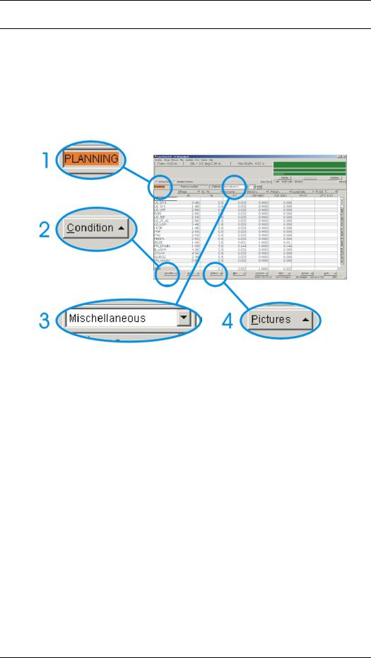
CARGOMASTER® may operate in either Online or Planning mode. (You will find more information regarding these two modes later on in this manual). For now, we will be running in Online mode, so check whether the text at circle #1 (above) reads ONLINE: or PLANNING: If it shows ONLINE that’s fine, and you can move on to step 3. If it shows PLANNING (Like the example does) please continue with step 2.
Step 2 – Activating online mode
Assuming the system is NOT running in online mode, click the button in the lower left corner of the screen (The one inside circle #2) – It is named “Condition”. From the menu that appears, click “Current Online”. Verify that the text at circle #1 now reads “Online”. If so, move on to step 3. (Otherwise, you may have to repeat step 2)
Step 3 – Select tanks to view
This step requires that you (or someone else) know which tanks that currently have ongoing operations. We assume those are the tanks you prefer to
13 - Operators Manual

CARGOMASTER®5
monitor? The example above shows the “Miscellaneous” group, but you can select any existing group listed here – a click on the little down-arrow to the right will reveal available groups. Just click on the group you want to view. Note that whatever the screen looked like when you started, by selecting any group here, the ValueTable (numeric) view will come to focus. Step 4 shows you how to change this.
Step 4 - Select your preferred View
After completing Step 3 you should be monitoring the real situation of your tanks. You have two other choices on how to view the gauging data – the BarGraph and the TankPlan views. Try them both, and figure out for yourself what suits your needs.
The different vies are selected by clicking the “Pictures” button at the bottom of the screen (As indicated in the example above).
Operators Manual - 14

CARGOMASTER®5
3. A Planning Example
CARGOMASTER® considers any tank to be of a certain type. The native types are Cargo, Ballast, Fuel/Lubrication, Temperature, Solids or Misc. Tanks of the same type may be grouped together. This is a convenient, and necessary feature whenever the volume of a certain cargo – or grade grows beyond the capacity of one single tank. Treating several tanks as a group allows for controlling e.g. density and alarm settings from one single point. You will also be able to print out surveyand other reports with totals for the whole group. (CARGOMASTER® also allows tanks from various groups be treated together without breaking up the groups – more on that in Reference - Groups)
All configurations of groups can be stored and recalled at a later point. This allows for re-use of specific voyage, discharge or loading configurations. If you have set up one or more groups of tanks, with applied alarm settings, densities etc., you can save or retrieve it under a preferred label. Such a label is in CARGOMASTER® defined as a condition.
As an aide for preparing in advance or to test a specific configuration, a CARGOMASTER® condition can be set to operate in Planning mode.
This chapter will take you on a little tour aboard the chemical tanker MT SKARPEFJORD. First, we will create a new condition. Within this condition we will create a new group containing multiple tanks. Finally, we will set this condition into online mode.
Since hardly any vessels are configured the same way, this example can only serve as an indication on how to use the CARGOMASTER® program and it’s basic functions. Let us start with a glance at a few terms:
15 - Operators Manual
CARGOMASTER®5
Online or Planning mode?
The normal state for a CARGOMASTER® condition to run during loading / discharge operations would be online mode. In online mode, all values presented on the screen will be read from the gauges installed in the various tanks.
Planning mode is somewhat different. Here, to let you test any distribution of cargo in tanks, you may insert your own values in e.g. the VOL% fields. Combined with the Loadcalc (which is optional) the operator can quickly determine whether the suggested cargo load will be within safe stability limits.
It is not recommended to run any conditions in planning mode during load or discharge operations!
Vessels carrying the same cargo all the time, like crude oil tankers, and maybe even oilrigs will often be running the same online condition for all situations. On such vessels it will be less likely that any new cargo distribution across multiple tanks would occur.
Note: An Online condition will always be running in the background whenever working with a planning condition. This ensures that alarms and data presented in the Online window will always be real-time data.
Creating a new planning condition
Let us start with that – creating a new planning condition where we can set up our new tank groups:
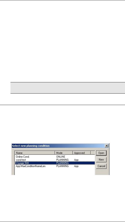
In the lower left corner of the screen, there is a button called “Condition”. Click it. (Or, press Alt + C). Then, select the “planning” option (press P). This should open the “Select new planning condition” dialogue. Select “New” (Alt + N)
Screenshot 2 The New planning condition dialogue
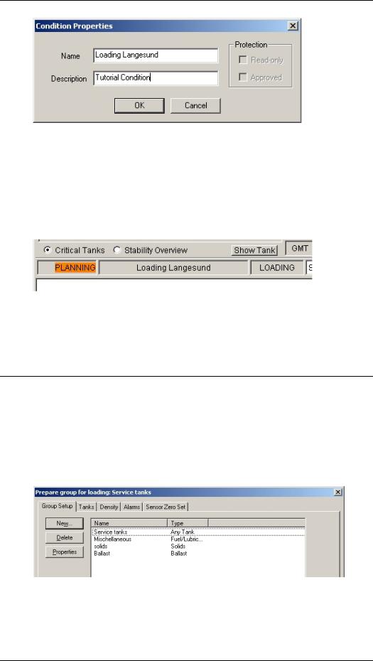
A new “pop-up” appears, called “Condition Properties”. In our example, we call the new condition “Loading Langesund”. We also gave a description for this condition as you see in the figure below. You may name your conditions whatever you like.
Operators Manual - 16
CARGOMASTER®5
Screenshot 3 Naming the new condition
By pressing “OK” (or hit the Enter button) this condition is now created, and set active. This will also show in the main views. First, the mode field should now have a blinking orange background behind the text “Planning”. Next, the name of the condition should appear to the right of this field. See below.
Screenshot 4 Verifying that the correct condition is active
With our new condition up running, we are ready for the group setup. Or, as it’s called in CARGOMASTER® - “Prepare for loading”.
Prepare for loading
Define Group
In the port of Langesund we will be taking approximately 1.900 m³ of Sulphuric Acid.
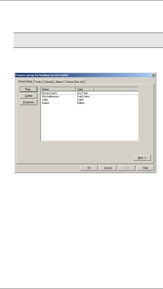
Press F2 to bring up the “Prepare group for loading” dialogue:
Screenshot 5 Prepare for Loading – Group Setup
17 - Operators Manual

CARGOMASTER®5
This window contains multiple TAB’s, each showing different “pages”. On the first page, showing above, already existing groups are listed. CARGOMASTER® allows for a total of 60 groups in one condition.
Selecting the New option, we will create a group to carry our Sulphuric Acid:
Screenshot 6 Prepare for loading – Group Properties
Here, we have given the group a name, specified a Cargo type tank, we have selected a color to identify the group in the TankPlan view and, finally, we have entered an estimated volume of 1.900m³.
Select tanks
Next step is to allocate sufficient tank capacity for this grade. By clicking the Tanks tab, or the Next button, we bring up a list of available tanks of the selected type. Some tanks that are already allocated to other groups may also show. The two columns on this page displays tankname, any existing group allocation and the tank’s 98% volume capacity.
Screenshot 7 Prepare for Loading – Tanks tab
Operators Manual - 18
CARGOMASTER®5
For this example we have selected the C4 and C5 tanks, whose joint 98% capacity is just above the expected volume we need.
The -> and <- arrow buttons are used for selecting / de-selecting tanks. The buttons on the right are used for altering the order of the tanks, including separators for increased readability.
Density settings
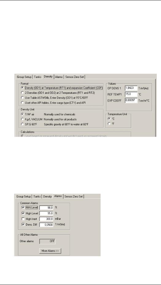
The 3rd step in this process is to enter the correct density or API. The Density tab gives several choices.
Screenshot 8 Prepare for loading – Density settings
We have entered the characteristic density for this cargo, according to the shore specifications. You can read more about the density settings and possible options regarding CARGOMASTER®’s ability to measure the exact density in the Reference section of this manual.
Alarm settings
Selecting the Alarms tab, should bring up the following page:
Screenshot 9 Prepare for Loading – Alarms tab
19 - Operators Manual

CARGOMASTER®5
Here, we have enabled alarms for 98%, 95% and for a difference in density of more than 0.05 T/m³ between the OD1 value (See above) and the actual measured density.
Pressing the More Alarms button will open for even more alarm options, however not necessarily relevant to a loading situation… Alarm limits and enabling may also be found in the ValueTable view (Alt + F3).
Zero adjust – sensor optimization
There is one final step to this sequence. The zero adjustment of any pressure sensors found in the tanks belonging to this group. However, some restrictions for zero adjustment apply:
•To zero adjust any Inert Gas Pressure (IGP) sensors, the tank must be open to air.
•To zero adjust any bottom or upper sensors, the sensors cannot be submerged in fluid.
•Temperature elements do not normally need zero adjustment.
•The atmospheric (reference) sensor should NOT be adjusted!
We recommend zero adjustment to be performed immediately before loading. More details about this issue are found in Zero adjustments on page 36.
Bringing the new condition online
With our new condition running in Planning mode, we are now ready to start loading. Or are we?
In the opening of the chapter “A planning Example” we wrote that
It is not recommended to run any conditions in planning mode during load or discharge operations
And why is that? When running in planning mode, data will not be updated in the ordinary views. Any warnings or info that displays in the Online Window will only be valid for the currently running online condition, and so will any active alarms. This means we will have to bring our planning condition Online before attempting to start the loading operations.
Press Ctrl + Alt + F1 (Or select Condition – Online from the bottom menu buttons)
Screenshot 10 The Online Condition selector
Operators Manual - 20
CARGOMASTER®5
When we created the new condition, another condition was already running in Online mode. There will always be an Online condition; without that, the CARGOMASTER® will not run. This also means that you cannot have the same condition both Online and Planning at the same time.
To bring our condition Online, select it (like in Screenshot 10) and hit Open. Checking the mode and name of the current condition should now show on the main screen, like below:
Screenshot 11 Condition running in Online mode
21 - Operators Manual

CARGOMASTER®5
4. Reference
Groups
CARGOMASTER® sees any tank to be of a certain type. The native types are Cargo, Ballast, Fuel/Lubrication, Temperature, Solids or Misc types. Tanks of the same type can be grouped together. (Scratch Groups can be used to group tanks of different types)
Groups are usually set up from the Loading menus (F2), but single tanks can be added or removed from a group within the ValueTable also.
By organising tanks into groups one achieves common handling of densities, alarm limits, grade sums and averages and sorted survey reports.
Group modes
Groups may be set in different modes. Each mode has a specific set of alarms and limits.
Loading: A new group is automatically set in loading mode. Loading mode enables typical alarm settings and levels that apply for a loading situation. Suggested alarms are HH Level, H Level, H Inert and Density Difference.
Discharge: Suggested alarms enabled for this mode are LoLo Vol%, Lo Vol% and LO Inert.
Seagoing: Suggested alarms are Volume change (See note), high and low temperatures and high and low inert pressures.
Set group to loading
Press F2 or select menu Group – Loading. Select the group you want to set to Loading and click OK.
Set group to Discharge
Press Shift+F2 or select menu Group – Discharge. Select group and click OK.
Operators Manual - 22
CARGOMASTER®5
Set group to Seagoing
Accessed by pressing Alt+F2 or select menu Group – Seagoing. You will be asked whether to set one or all groups in this mode. Check/uncheck the different alarms to enable/disable and adjust any alarm limits as needed.
Note: The Volume Change option will set the HiVol and LoVol limits in accordance to the current level, so that if current Volume is 70%, the HiVol will be 73% and the LoVol will be set at 67%.
Setting up a new group
Accessed from Group- Loading or press F2.
Screenshot 12 The Group Setup tab
New: |
Creates a new group in loading mode. The dialogue |
|
window lets you specify a name for the group, the |
|
color for which it is displayed in TankPlan, required |
|
volume for the group and what type of tanks the group |
|
should host. |
Delete: |
Deletes the currently selected group or groups. |
Properties: |
Here you can display or edit name, color, volume and |
|
type for the currently selected group |
23 - Operators Manual
 Loading...