


 Loading...
Operating Instructions
OPTISWITCH 3300 C with NAMUR output

Contents
2
Contents
1About this document
1.1 Function . . . . . . . . . . . . . . . . . . . . . . . . . . . . . 4 1.2 Target group . . . . . . . . . . . . . . . . . . . . . . . . . . 4 1.3 Symbolism used . . . . . . . . . . . . . . . . . . . . . . . 4
2For your safety
2.1 |
Authorised personnel . . . . . . . . . . . . . . . . . . . . |
5 |
2.2 |
Appropriate use. . . . . . . . . . . . . . . . . . . . . . . . |
5 |
2.3 |
Warning about misuse . . . . . . . . . . . . . . . . . . . |
5 |
2.4 |
CE conformity . . . . . . . . . . . . . . . . . . . . . . . . . |
5 |
2.5 |
SIL conformity . . . . . . . . . . . . . . . . . . . . . . . . . |
6 |
2.6 Safety instructions for Ex areas . . . . . . . . . . . . |
6 |
|
3 Product description |
|
|
3.1 |
Configuration. . . . . . . . . . . . . . . . . . . . . . . . . . |
7 |
3.2 |
Principle of operation . . . . . . . . . . . . . . . . . . . . |
7 |
3.3 |
Operation . . . . . . . . . . . . . . . . . . . . . . . . . . . . |
8 |
3.4 |
Storage and transport . . . . . . . . . . . . . . . . . . . |
9 |
4Mounting
4.1 General instructions. . . . . . . . . . . . . . . . . . . . . 10 4.2 Mounting instructions . . . . . . . . . . . . . . . . . . . . 11
5Connecting to voltage supply
5.1 Preparing the connection . . . . . . . . . . . . . . . . . 16
5.2 Connection steps. . . . . . . . . . . . . . . . . . . . . . . 16
5.3 Wiring plan, single chamber housing. . . . . . . . . 17
6Set up
6.1 General. . . . . . . . . . . . . . . . . . . . . . . . . . . . . . 20 6.2 Adjustment elements . . . . . . . . . . . . . . . . . . . . 20 6.3 Function chart . . . . . . . . . . . . . . . . . . . . . . . . . 21 6.4 Recurring function test . . . . . . . . . . . . . . . . . . . 22
7Maintenance and fault rectification
7.1 Maintenance . . . . . . . . . . . . . . . . . . . . . . . . . . 25 7.2 Rectify faults . . . . . . . . . . . . . . . . . . . . . . . . . . 25
7.3 Exchange the electronics . . . . . . . . . . . . . . . . . 26
7.4 Instrument repair . . . . . . . . . . . . . . . . . . . . . . . 28
8Dismounting
8.1 Dismounting procedure . . . . . . . . . . . . . . . . . . 29 8.2 Disposal . . . . . . . . . . . . . . . . . . . . . . . . . . . . . 29
OPTISWITCH 3300 C - with NAMUR output
060830-EN-31358

Contents
31358-EN-060830
9Supplement
9.1 Technical data. . . . . . . . . . . . . . . . . . . . . . . . . 30 9.2 Dimensions . . . . . . . . . . . . . . . . . . . . . . . . . . . 34
Supplementary operating instructions manuals
Information:
OPTISWITCH 3300 C is available in di erent versions. Depending on the selected version, supplementary operating instructions manuals may also come with the shipment. The supplementary operating instructions manuals are listed in section "Product description.
Operating instructions manuals for accessories and replacement parts
Tip:
To ensure reliable setup and operation of your OPTISWITCH 3300 C, we o er accessories and replacement parts. The associated documents are:
•Operating instructions manual "Oscillator"
•Operating instructions manual "Lock fitting"
OPTISWITCH 3300 C - with NAMUR output |
3 |
About this document
1 About this document
1.1 Function
This operating instructions manual has all the information you need for quick setup and safe operation. Please read this manual before you start setup.
1.2 Target group
This operating instructions manual is directed to trained, qualified personnel. The contents of this manual should be made available to these personnel and put into practice by them.
4
1.3 Symbolism used
Information, tip, note
This symbol indicates helpful additional information.
Caution: If this warning is ignored, faults or malfunctions can result.
Warning: If this warning is ignored, injury to persons and/or serious damage to the instrument can result.
Danger: If this warning is ignored, serious injury to persons and/or destruction of the instrument can result.
Ex applications
This symbol indicates special instructions for Ex applications.
•List
The dot set in front indicates a list with no implied sequence.
àAction
This arrow indicates a single action.
1Sequence
Numbers set in front indicate successive steps in a procedure.
OPTISWITCH 3300 C - with NAMUR output |
060830-EN-31358 |
|

31358-EN-060830
For your safety
2 For your safety
2.1 Authorised personnel
All operations described in this operating instructions manual must be carried out only by trained specialist personnel authorised by the operator. For safety and warranty reasons, any internal work on the instruments must be carried out only by personnel authorised by the manufacturer.
2.2 Appropriate use
OPTISWITCH 3300 C is a sensor for level detection.
Detailed information on the application range of OPTISWITCH 3300 C is available in chapter "Product description".
2.3 Warning about misuse
Inappropriate or incorrect use of the instrument can give rise to application-specific hazards, e.g. vessel overfill or damage to system components through incorrect mounting or adjustment.
2.4 General safety instructions
OPTISWITCH 3300 C is a high-tech instrument requiring the strict observance of standard regulations and guidelines. The user must take note of the safety instructions in this operating instructions manual, the country-specific installation standards (e.g. the VDE regulations in Germany) as well as all prevailing safety regulations and accident prevention rules.
2.5 CE conformity
OPTISWITCH 3300 C is in CE conformity with EMC (89/336/ EWG), fulfils NAMUR recommendation NE 21 and is in CE conformity with LVD (73/23/EWG).
Conformity has been judged according to the following standards:
•EMC:
-Emission EN 61326: 1997 (class B)
-Susceptibility EN 61326: 1997/A1:1998
•LVD: EN 61010-1: 2001
OPTISWITCH 3300 C - with NAMUR output |
5 |

For your safety
6
2.6 SIL conformity
OPTISWITCH 3300 C fulfills the requirements of functional safety according to IEC 61508/IEC 61511. You can find further information in the supplementary instructions manual "Safety
Manual - Functional safety (SIL) OPTISWITCH 3XXX".
2.7 Safety instructions for Ex areas
Please note the Ex-specific safety information for installation and operation in Ex areas. These safety instructions are part of the operating instructions manual and come with the Exapproved instruments.
OPTISWITCH 3300 C - with NAMUR output |
060830-EN-31358 |
|
Product description
|
3 |
Product description |
|
3.1 Configuration |
|
Scope of delivery |
The scope of delivery encompasses: |
|
|
• OPTISWITCH 3300 C level sensor |
|
|
• |
Documentation |
|
|
- this operating instructions manual |
|
|
- Supplementary instructions manual "Plug connector for |
|
|
level sensors" (optional) |
|
|
- Ex specific safety instructions (with Ex versions), if |
|
|
necessary further certificates |
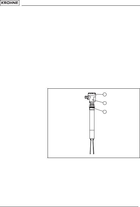
Components |
OPTISWITCH 3300 C consists of the following components: |
|
|
• |
Housing cover |
|
• Housing with electronics |
|
|
• process fitting with tuning fork |
|
|
|
1 |
|
|
2 |
|
|
3 |
31358-EN-060830
|
Fig. 1: OPTISWITCH 3300 C with plastic housing |
|
|
1 |
Housing cover |
|
2 |
Housing with electronics |
|
3 |
Process fitting |
|
3.2 |
Principle of operation |
Area of application |
OPTISWITCH 3300 C is a level sensor with tuning fork for level |
|
|
detection. |
|
OPTISWITCH 3300 C - with NAMUR output |
7 |

Product description
Physical principle
Power supply
8
It is designed for industrial use in all areas of process technology and is preferably used for bulk solids.
Typical applications are overfill and dry run protection. Thanks to its simple and robust measuring system, OPTISWITCH 3300 C is virtually una ected by the chemical and physical properties of the bulk solid.
It functions even when exposed to strong external vibration or changing products.
Solid detection in water
If OPTISWITCH 3300 C was ordered for detection of solids in water, the tuning fork is adjusted to the density of water. In the air or when covered by water (density: 1 g/cm³/0.036 lbs/in)
OPTISWITCH 3300 C signals "uncovered". Only if the vibrating element is also covered with solids (e.g. sand, sludge, gravel etc.) will the sensor signal "covered".
Fault monitoring
The electronics of OPTISWITCH 3300 C continuously monitors the following criteria:
•Correct vibrating frequency
•Line break to the piezo drive
If one of these faults is detected, the electronics signals this via a defined current to the signal conditioning instrument. The connection cable to the vibrating element is also monitored.
The tuning fork is piezoelectrically energised and vibrates at its mechanical resonance frequency of approx. 150 Hz. When the tuning fork is submerged in the product, the vibration amplitude changes. This change is detected by the integrated oscillator and converted into a switching command.
OPTISWITCH 3300 C with NAMUR electronics can be connected to di erent NAMUR amplifiers depending on your requirements. The specifications for NAMUR amplifiers are available in the "Technical data".
The exact range of the power supply is stated in the "Technical data" in the "Supplement".
3.3 Operation
With the factory setting, products with a density of >0.02 g/cm³ (>0.0008 lbs/in³) can be measured. The instrument can also be adapted to products with lower density >0.008 g/cm³
(>0.0003 lbs/in³).
OPTISWITCH 3300 C - with NAMUR output
060830-EN-31358

Product description
On the electronics module you will find the following indicating
|
and adjustment elements: |
|
|
• signal lamp for indication of the switching condition (yellow) |
|
|
• potentiometer for adaptation to the product density |
|
|
• Mode switch to select the switching condition (reverse |
|
|
|
characteristics) |
|
• |
Simulation key |
|
3.4 |
Storage and transport |
Packaging |
Your instrument was protected by packaging during transport. |
|
|
Its capacity to handle normal loads during transport is assured |
|
|
by a test according to DIN 55439. |
|
|
The packaging of standard instruments consists of environ- |
|
|
ment-friendly, recyclable cardboard. In addition, the sensor is |
|
|
provided with a protective cover of cardboard. For special |
|
|
versions PE foam or PE foil is also used. Dispose of the |
|
|
packaging material via specialised recycling companies. |
|
Storage and transport tem- |
• |
Storage and transport temperature see "Supplement - |
perature |
|
Technical data - Ambient conditions" |
|
• Relative humidity 20 … 85 % |
|
31358-EN-060830
OPTISWITCH 3300 C - with NAMUR output
9
Mounting
Switching point
Moisture
Transport
Pressure/Vacuum
10
4 Mounting
4.1 General instructions
In general, OPTISWITCH 3300 C can be mounted in any position. The instrument must be mounted in such a way that the vibrating element is at the height of the requested switching point.
Use the recommended cables (see chapter "Connecting to power supply") and tighten the cable gland.
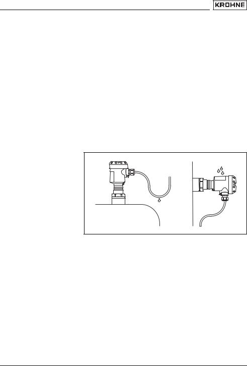
You can give your OPTISWITCH 3300 C additional protection against moisture penetration by leading the connection cable downward in front of the cable entry. Rain and condensation water can thus drain o . This applies mainly to mounting outdoors, in areas where moisture is expected (e.g. by cleaning processes) or on cooled or heated vessels.
Fig. 2: Measures against moisture penetration
Do not hold OPTISWITCH 3300 C on the vibrating element. Especially with flange and tube versions, the sensor can be damaged by the weight of the instrument.
Remove the protective cover just before mounting.
The process fitting must be sealed if there is gauge or low pressure in the vessel. Before use, check if the seal material is resistant against the measured product and the process temperature.
The max. permissible pressure is stated in the "Technical
data" in the "Supplement" or on the type label of the sensor. 31358 -EN
OPTISWITCH 3300 C - with NAMUR output
060830-
|
|
Mounting |
Handling |
The vibrating level switch is a measuring instrument and must |
|
|
|
be treated accordingly. Bending the vibrating element will |
|
|
destroy the instrument. |
|
|
Warning: |
|
|
The housing must not be used to screw in the instrument! |
|
|
Applying tightening force on the housing can damage its |
|
|
internal mechanical parts. |
|
|
To screw in, use the hexagon above the thread. |
|
4.2 Mounting instructions |
Agitators and fluidization |
Agitators, equipment vibration, etc., can cause the level switch |
|
to be subjected to strong lateral forces. For this reason, do not |
|
use an overly long extension tube for OPTISWITCH 3300 C, |
|
but check if you can mount a short level switch on the side of |
|
the vessel in horizontal position. |
|
Extreme vibration caused by the process or the equipment, e. |
|
g. agitators or turbulence in the vessel e.g. from fluidization, |
|
can cause the extension tube of OPTISWITCH 3300 C to |
|
vibrate in resonance. This leads to increased stress on the |
|
upper weld joint. Should a longer tube version be necessary, |
|
you can provide a suitable support or guy directly above the |
|
tuning fork to secure the extension tube. |
|
This measure applies particularly to applications in Ex areas. |
|
Make sure that the tube is not subjected to bending forces |
|
through this measure. |
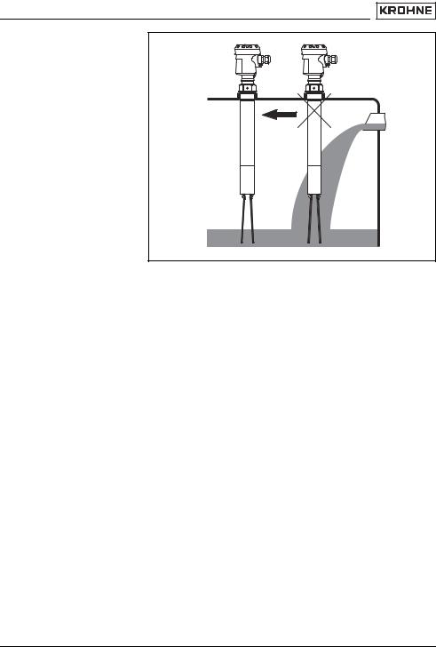
Inflowing medium |
If OPTISWITCH 3300 C is mounted in the filling stream, |
|
unwanted switching signals may be generated. Mount OPTI- |
|
SWITCH 3300 C at a location in the vessel where no disturbing |
|
influence from e.g. filling openings, agitators etc. can occur. |
|
This applies particularly to instrument types with long |
|
extension tube. |
31358-EN-060830
OPTISWITCH 3300 C - with NAMUR output
11
Mounting
Lock fitting
Socket
Material cone
12
Fig. 3: Inflowing medium
OPTISWITCH 3300 C can be mounted with a lock fitting for height adjustment. Take note of the pressure information of the lock fitting.
The vibrating element should protrude into the vessel to avoid buildup. For that reason, avoid using mounting bosses for flanges and screwed fittings. This applies particularly to use with adhesive products.
In silos for bulk solids, material cones can form and change the switching point. Please keep this in mind when installing the sensor in the vessel. We recommend selecting an installation location where the vibrating fork detects an average value of the material cone.
The tuning fork must be mounted at a location that takes the arrangement of the filling and emptying apertures into account.
To compensate measurement errors caused by the material cone in cylindrical vessels, the sensor must be mounted at a distance of d/6 from the vessel wall.
OPTISWITCH 3300 C - with NAMUR output |
060830-EN-31358 |
|
Loading...