


BM90
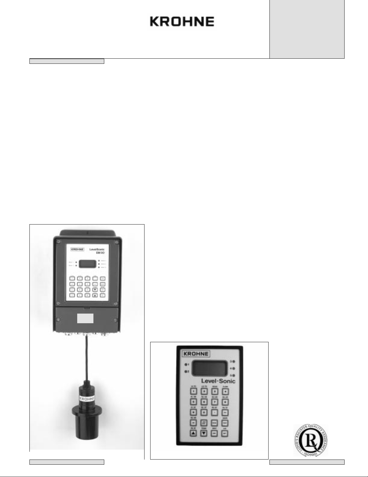
Level-Sonic
Non contact level gauging
using ultrasonic waves
Inst allation and
operating
instructions
BM90/BM90L
BM90E/BM90LE
05/99
KROHNE S.A.
CERTIFIED
ISO 9001
C E
BM90 / L
BM 90 E / LE Panel mounted

2
LEVEL-SONIC BM90 SERIES
Contents Page
1. Introduction . . . . . . . . . . . . . . . . . . . . . . . . . . . . . . . . . . .3
1.1. Level-Sonic BM90 . . . . . . . . . . . . . . . . . . . . . . . . . . . . . . . . . . . . . . . . . . . . . . . . . . . . . . . . . .3
1.2. Initial start up Level-Sonic BM90 . . . . . . . . . . . . . . . . . . . . . . . . . . . . . . . . . . . . . . . . . . . . . . .4
1.2.1. How to view parameters . . . . . . . . . . . . . . . . . . . . . . . . . . . . . . . . . . . . . . . . . . . . . . . . . . . . .4
1.2.2. How to change parameters . . . . . . . . . . . . . . . . . . . . . . . . . . . . . . . . . . . . . . . . . . . . . . . . . . .4
1.2.3. Programming example . . . . . . . . . . . . . . . . . . . . . . . . . . . . . . . . . . . . . . . . . . . . . . . . . . . . . .5
1.3. Program checking . . . . . . . . . . . . . . . . . . . . . . . . . . . . . . . . . . . . . . . . . . . . . . . . . . . . . . . . . .5
1.3.1. Program correction . . . . . . . . . . . . . . . . . . . . . . . . . . . . . . . . . . . . . . . . . . . . . . . . . . . . . . . . .5
2. Inst allation . . . . . . . . . . . . . . . . . . . . . . . . . . . . . . . . . . . .6
2.1. Converter . . . . . . . . . . . . . . . . . . . . . . . . . . . . . . . . . . . . . . . . . . . . . . . . . . . . . . . . . . . . . . . . .6
2.1.1. BM90 / L Wall mounted converter . . . . . . . . . . . . . . . . . . . . . . . . . . . . . . . . . . . . . . . . . . . . . .6
2.1.2. Transducer wiring for BM90 / L . . . . . . . . . . . . . . . . . . . . . . . . . . . . . . . . . . . . . . . . . . . . . . . .7
2.1.3 Transducer Cable Extensions for BM90 / L . . . . . . . . . . . . . . . . . . . . . . . . . . . . . . . . . . . . . . .8
2.1.4. BM90 E/ LE Panel mounted converter . . . . . . . . . . . . . . . . . . . . . . . . . . . . . . . . . . . . . . . . . .9
2.1.5. Transducer wiring for BM90 E / LE . . . . . . . . . . . . . . . . . . . . . . . . . . . . . . . . . . . . . . . . . . . . .9
2.1.6 Tranducer Electrical Connections for BM90 E / LE . . . . . . . . . . . . . . . . . . . . . . . . . . . . . . . .10
2.1.7 Transducer Cable Extensions for BM90 E / LE . . . . . . . . . . . . . . . . . . . . . . . . . . . . . . . . . . .10
2.2. Transducer mounting . . . . . . . . . . . . . . . . . . . . . . . . . . . . . . . . . . . . . . . . . . . . . . . . . . . . . .11
2.2.1. Alternativ mounting . . . . . . . . . . . . . . . . . . . . . . . . . . . . . . . . . . . . . . . . . . . . . . . . . . . . . . . .12
2.3. Temperature sensor . . . . . . . . . . . . . . . . . . . . . . . . . . . . . . . . . . . . . . . . . . . . . . . . . . . . . . .14
3. Programming . . . . . . . . . . . . . . . . . . . . . . . . . . . . . . . . .15
3.1. Keypad definitions . . . . . . . . . . . . . . . . . . . . . . . . . . . . . . . . . . . . . . . . . . . . . . . . . . . . . . . . .15
3.2. Display descriptions . . . . . . . . . . . . . . . . . . . . . . . . . . . . . . . . . . . . . . . . . . . . . . . . . . . . . . .15
3.3. Security code . . . . . . . . . . . . . . . . . . . . . . . . . . . . . . . . . . . . . . . . . . . . . . . . . . . . . . . . . . . . .16
3.4. Application programming . . . . . . . . . . . . . . . . . . . . . . . . . . . . . . . . . . . . . . . . . . . . . . . . . . . .16
3.5. Programming . . . . . . . . . . . . . . . . . . . . . . . . . . . . . . . . . . . . . . . . . . . . . . . . . . . . . . . . . . . . .16
3.5.1. Parameter index . . . . . . . . . . . . . . . . . . . . . . . . . . . . . . . . . . . . . . . . . . . . . . . . . . . . . . . . . .17
3.5.2. Parameter definitions . . . . . . . . . . . . . . . . . . . . . . . . . . . . . . . . . . . . . . . . . . . . . . . . . . . . . .18
4. Examples . . . . . . . . . . . . . . . . . . . . . . . . . . . . . . . . . . . . . . . . . . . . . . . . . . . . . . . . . .27
4.1. Level measurement mode . . . . . . . . . . . . . . . . . . . . . . . . . . . . . . . . . . . . . . . . . . . . . . . . . . .27
4.2. Measurement with volumetric conversion . . . . . . . . . . . . . . . . . . . . . . . . . . . . . . . . . . . . . . .28
4.3. Pump control . . . . . . . . . . . . . . . . . . . . . . . . . . . . . . . . . . . . . . . . . . . . . . . . . . . . . . . . . . . . .29
4.4. Differential level mode . . . . . . . . . . . . . . . . . . . . . . . . . . . . . . . . . . . . . . . . . . . . . . . . . . . . . .30
4.6. Open channel flowmeter . . . . . . . . . . . . . . . . . . . . . . . . . . . . . . . . . . . . . . . . . . . . . . . . . . . .31
4.7. Open channel flowmeter with penstock control . . . . . . . . . . . . . . . . . . . . . . . . . . . . . . . . . . .32
5. Fault finding . . . . . . . . . . . . . . . . . . . . . . . . . . . . . . . . . .33
5.1. Trouble shooting . . . . . . . . . . . . . . . . . . . . . . . . . . . . . . . . . . . . . . . . . . . . . . . . . . . . . . . . . .33
5.2. Programming sheet . . . . . . . . . . . . . . . . . . . . . . . . . . . . . . . . . . . . . . . . . . . . . . . . . . . . . . . .36
6. Technical data Level-Sonic . . . . . . . . . . . . . . . . . . . . . .37
6.1. Converter . . . . . . . . . . . . . . . . . . . . . . . . . . . . . . . . . . . . . . . . . . . . . . . . . . . . . . . . . . . . . . . .37
6.2. Transducer . . . . . . . . . . . . . . . . . . . . . . . . . . . . . . . . . . . . . . . . . . . . . . . . . . . . . . . . . . . . . .37
Appendix 1 : Vessel - Flume linearisation . . . . . . . . . . . . . . . . . . . . . . . . . . . . . . . . . . . . . . . . . . . . . . .38
Appendix 2 : Serial Communications BM90 L only . . . . . . . . . . . . . . . . . . . . . . . . . . . . . . . . . . . . . . .40
Appendix 3 : Parameter Settings . . . . . . . . . . . . . . . . . . . . . . . . . . . . . . . . . . . . . . . . . . . . . . . . . . . . . .41

1. Introduction
1.1. Level-Sonic BM90
The KROHNE S.A. Level-Sonic BM90/BM90E is a multipurpose liquid level measurement and flow control instrument.
The KROHNE S.A. Level-Sonic BM90L/BM90LE is also available for powder and granulate level.
It consists of two main elements, a microprocessor based transceiver and a high-efficiency transducer.
Ultrasonic pulses are transmitted by the transducer to the surface of the material to be monitored and, within millisec-
onds, are reflected back to the transducer. The time period between transmission and reception of the pulses is
directly proportional to the distance between the transducer and the material.
The Level-Sonic BM90 microprocessor computes this time period continuously for all echoes received and analyses
which is the correct reflection from the surface being monitored. It uses this data as the basis for giving control outputs
and displays, in useable engineering units.
Level-Sonic BM90 is capable of the following functions :
a) Level Measurement
b) Volume Measurement
c) Distance Measurement
d) Pump Control
e) Differential Level Measurement
f) Open Channel Flow Measurement
WARNING
DO NOT OPEN THE ELECTRICAL COVER WHEN THE POWER IS ON TO
THE SUPPLY OR RELAY TERMINALS.
NOTE : There is no need to remove the upper cover. If you need to access to the RS232 or RS485 terminal for the
BM90L then you have to open it.
IN THIS EVENTUALLITY, PLEASE REMOVE IT GENTLY, A FLAT CABLE IS ATTACHED TO THE COVER. TAKE
CARE NOT TO DESTROY IT.
3

4
1.2. Initial st art up Level-Sonic
The Level-Sonic BM90 system requires programming by
the operator to obtain the required measurements and
control. To become familiar with the use of the system, it
is suggested that the following Q UICK START G UIDE is
used before the instrument is installed.
Quick Start Guide :
1. Connect power and transducer cables as defined on
the instrument.
ac Power Supply Transducer dc Power Supply
[ 1 ] [ 2 ] [ 3 ] Terminal Nos: [ 19 ] [ 20 ] [21 ] [27 ] [28]
E N L Black Blue Screen +ve -ve
2. The instrument is supplied factory set on initial power
up to work in distance measurement up to 10 metres
from the transducer on the Level-Sonic BM90/E and 15
metres on the Level-Sonic BM90L/LE.
3. Hold the transducer approximately 1.5 metres from a
flat surface and switch on.
After a short period, the display will show the distance
(e.g. 1.50) between the transducer and the surface.
If the transducer is now moved slowly towards the sur-
face, the reading should decrease. This shows that the
unit is correctly wired and is operating as expected in
response to the reduction in distance.
If the reading increases as the transducer is moved
towards the surface, it indicates that the unit has been
previously programmed to read level not distance.
1.2.1. How to view parameters
The operational program for Level-Sonic BM90 is con-
tained within the parameters listed on Page 17 . Each
parameter instructs the unit to carry out a specific func -
tion. To look at the complete list of parameters, please
refer to chapter 3 but as an intitial guide proceed as fol -
lows :
Press ’MODE’, the display will show ’PROG’. (there
may be a delay of up to 6 seconds if the instrument is
busy). Press ’1’ immediately to obtain a display of
Pr.01 or the previous parameter number used.
It is now possible to key in any parameter number, via
the keypad. To display its value press ’DSP’. To
return to the parameter number press ’DSP’ again.
To view a sequence of parameter numbers, enter the
first one that is of interest and then press ’ s’ to
increase the parameter number or ’t’ to decrease the
parameter number.
Similarly, if a parameter value is displayed then press-
ing ’s’ or ’t ’ key will momentarily flash the next para-
meter number and then display that parameter value.
If a key is not pressed for a period of 30 seconds
the unit will automatically return to the run mode.
Press ’MODE’ to return Level-Sonic BM90 to the
’RUN’ mode.
1.2.2. How to change parameters
l Press ‘MODE‘ t o display ‘prog‘.
Whilst ’prog’ is displayed press ‘1‘
and the display will show either Pr.01
or previous Pr. number. If not Pr. 01
then press ‘1‘ to obtain display of
Pr.01.
l Press ‘DSP‘ t o display the value of Pr.01.
l Press ‘ENT‘ and the display will show ‘COdE‘
requesting that a security code is
entered.
l Press ‘9753‘ to enter the factory set security code.
(see page 16 to change code)
l Press ‘ENT‘ and the display will blink and show
either the default value of Pr.01 which is 2, or any other
value previously programmed into it.
The unit is now ready to be programmed.
Note : Whenever ‘COdE‘ is displayed, re-enter the secu-
rity code.
The display should now beshowing the value entered in
‘Pr.01‘ which is 2.
To change the value of this or any other parameter press
the new number required and ‘ENT‘. For our example
press 1 and ‘ENT‘ and the value of Pr.01 will change to 1
which means it is in level mode i.e. measuring liquid
height above datum.
Then using the ‘
s‘ key move to the other parameters that
require changing.
To change the value of any other parameter either use
the ’ s’ key to move to higher Pr numbers, or press ’DSP’
and then enter the Pr number required and press ’DSP’
again to display its value.
5
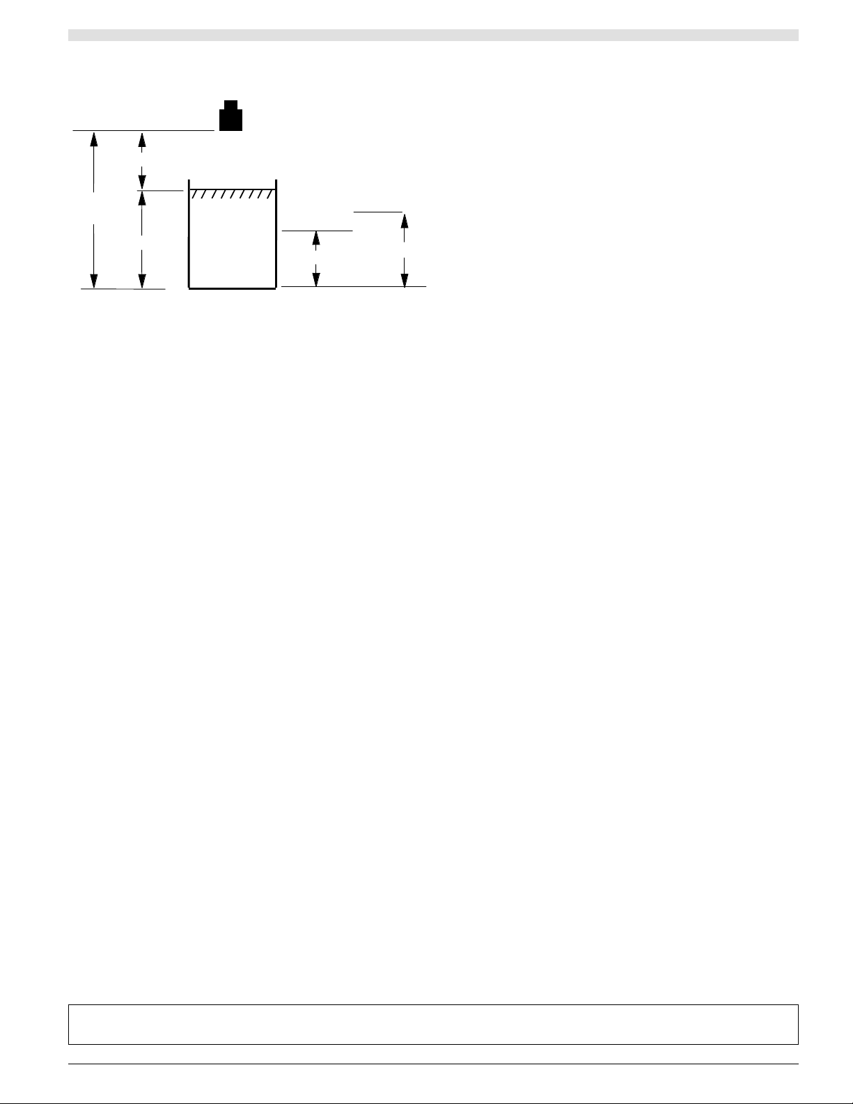
1.2.3. Programming example
The following example shows how Level-Sonic BM90
should be programmed for a simple level application
including setting a high alarm.
Having changed the value in Pr.01 to = 1 (level
Press
‘s‘ Display Pr.02 = 2 (units in meters)
‘s‘ Change Pr.03 = 1.5 (empty distance)
‘s‘ Change Pr.04 = 1.0 (operational span)
‘s‘ Change Pr. 05 = 0.5 (blanking distance)
‘s‘ Display Pr.06 = 1 (rate of change of
level in metres)
Press Pr.08 Change Pr.08 = 1 (relay 1 designated
normally energised)
‘s‘ Change Pr.09 = 0.7 (relay 1 set)
‘s‘ Change Pr.10 = 0.5 (relay 1 re-set)
MODE to return to normal running
For a full description of parameter options, please refer to
chapter 3.
Note : The display does not show the decimal point until
the first decimal figure is keyed in.
1.3. Program checking
To check that the previous program functions properly,
hold the transducer approximately 1.5 m above a surface
and press ‘MODE‘ to return to the run condition.
The display will read approximately zero.
If it displays LOST it is because the transducer is more
than the 1.5 metre (distance to furthest point) from your
target. Go closer and wait for LOST to change to 0.000
and then a level.
By slowly moving the transducer towards the surface, the
display will increase simulating a rising level. When the
display exceeds 0.7 the relay will switch, as indicated by
the light on relay 1, and if the transducer is then raised,
the display will decrease and the relay will reset below
0.5.
1.3.1. Program correction or
resetting factory defaults
If at any time you feel that a mistake has been made, the
following routine clears the program back to the known
starting position of the factory set values shown on
page 26. It is also advisable to return to the factory
default values before building a program for a new appli-
cation. This is achieved as follows :
Press
‘MODE‘ to display PROG .
1 immediately to display a Pr number
‘99 ‘ to display Pr.99.
D S P to show ====
‘C E ‘ to clear the display.
‘E N T‘ to display COdE requesting the security
code.
‘9753‘
‘E N T‘ the display will now show ‘t.rES‘
followed by ’P.rES’ and finally ‘====‘.
‘DSP‘ to display ‘Pr.99‘ and now the new
program can be entered.
The above is a brief introduction.
1.0 (Pr.4)
1.5
(Pr.3)
0.5 (Pr.5)
Relay 1 Reset
0.5 (Pr.10)
0.7 (Pr.9)
Nota : To understand programming completely it is necessary to read the detailed section describing Programming,
Section 3, along with the parameter descriptions, Section 4, and the examples, Section 5, before continuing.
6
2. Inst allation
The installation of the Level-Sonic BM90 unit is straight
forward, providing the guidelines in this chapter are fol -
lowed.
2.1. Converter
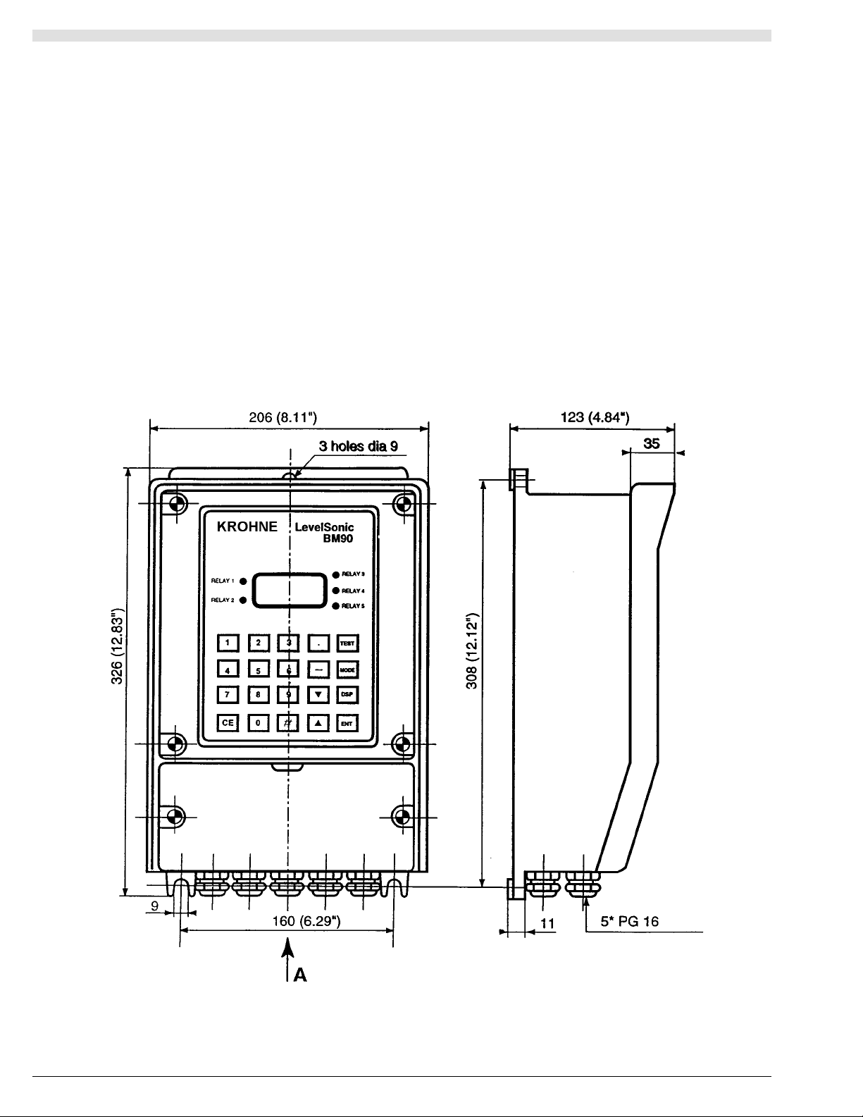
The BM90 / L unit (Fig 1) must be mounted on a flat sur-
face secured by the 3 mounting holes.
For the BM90 E/LE, see panel cut out figure 5.
When mounting the unit avoid vibration or close proximity
to high voltage cables, contactors and drive controls. The
unit should not be mounted in direct sunlight or in a con-
fined space where temperatures may exceed the normal
working temperature. If the unit is mounted outside it
must be protected from severe weather conditions.
Note : Electrical Connection
Converter instrument has 2 covers, the bottom one with 2
screws is protecting terminals. See Fig. 6 for the wiring
diagram. Replace cover after completion of wiring.
Note : Select the correct working voltages for AC
On converter instrument the voltage selector switch is on
the left hand side of the bottom PCB.
Note : If DC power supply is required, instruments will be
marked accordingly.
NOTE : There is no need to remove the upper cover. If
you need to access to the RS232 or RS485 terminal for
the BM90E then you have to open it.
IN THIS EVENTUALLITY, PLEASE REMOVE IT GEN-
TLY, A FLAT CABLE IS ATTACHED TO THE COVER.
TAKE CARE NOT TO DESTROY IT.
2.1.1 BM90 / L Wall mounted converter
Fig 1:
7
Figure 2:
AC power supply - connected:
Earth to terminal 1
Neutral to terminal 2
Live to terminal 3
The instrument will automatically accept either 110V or
230V AC –10%, 50Hz or 60Hz, 12VA. A time lag fuse
T160mA is fitted.
DC power supply - connected :
Positive +ve to terminal 27
Negative -ve t o terminal 28
The instrument will accept 24V DC + 25%, - 10%. 9W.
A time lag fuse T315mA is fitted.
5 SPDT Relays - rated 8A/250V AC/30V DC resistive,
with gold contacts for lower power switching, are connect-
ed to terminals 4 to 18, for activating external alarms,
contactors, pumps etc..
Transducer RZV15 - i s connected:
Black to terminal 19
Blue to terminal 20
Screen t o terminal 21
Temperature compensated transducer RZT15 -
is connected:
(Screen t o terminal 19
Must enable Pr.37 (Blue to terminal 20
(Black to terminal 22
Isolated Analogue - i s connected :
Screen t o terminal 24
Positive +ve to terminal 25
Negative -ve t o terminal 26.
Separate Temperature Compensation - when compen-
sation is provided by a separate temperature sensor, the
sensor should be connected with a shielded twisted pair
and connected:-
(Screen to terminal 21
Must enable Pr.37 (Core* t o terminal 22
(Core* to terminal 23
* The polarity of the cores is unimportant, but it is impor -
tant that the screen is connected only at the instrument
end and not at the temperature sensor end.
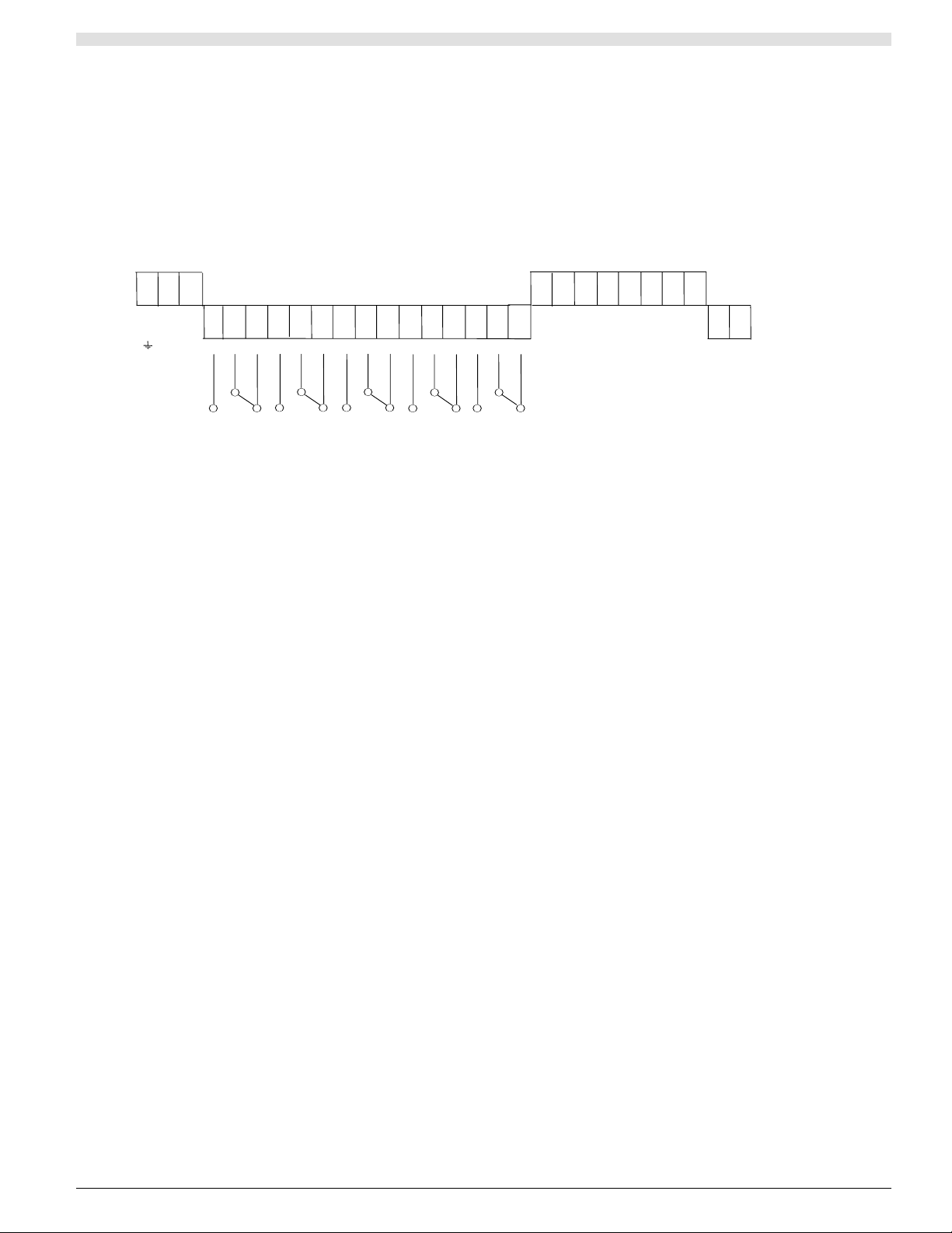
1 2 3
E N L
L2 L1
AC POWER
110/230 VAC
+10%/-10%
50/60 HZ
12VA
19 20 21 22 23 24 25 26
27 28
+ -
DC Power
21.6-30VDC
9W
Isolated
Analog
Output
+
-
4 5 6 7 8 9 10 11 12 13 14 15 16 17 18
RELAY 1
RELAY
RELAY
RELAY 5
RELAY 2
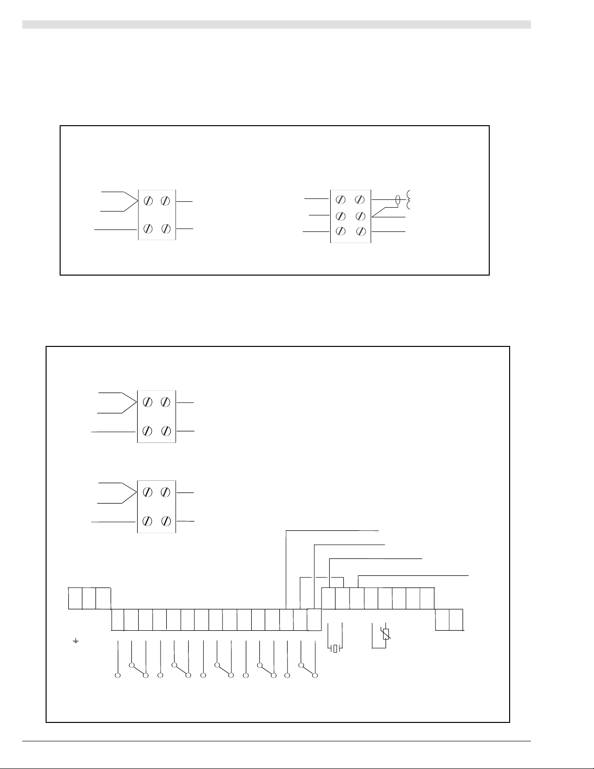
2.1.2. Transducer Wiring for BM90 / L
The wall mount instrument has two-part screw terminals. It can be powered from either an AC or DC supply.
Simultaneous AC & DC powering can be done through an external relay which switch on the other power when the
main one is off. The relay contact will be released when main power is off. Ask for scheme if necessary.
8
2.1.3. Transducer Cable Extensions for BM90 / L
Transducer cables may be extended using junction boxes as shown below in Figure 3:
Junction
Screen - Term 19
Standard Transducer
Transceiver
Core - Term 20
Transducer
Black
Screen
Blue
RG62AU
Temperature Compensation Transducer
RG62AU
Blue
Junction
Core - Term.22
Screen - Term.19
Core - Term. 20
Screen - Term.19
Transceiver
Transducer
Black
Screen
Figure 4:Transducer Wiring for Differential Mode
UP & DOWNSTREAM SHIELD
Junction
Screen - Term 19
Transceiver
Core - Term 18
Upstream Transducer
Black
Screen
RG62AU
Junction
Screen - Term 21
Transceiver
Core - Term 16
Downstream Transducer
Black
Screen
Blue
RG62AU
Extend transducer cable if necessary
with RG62AU as shown.
1 2 3
E N L
L 2 L1
AC POWER
110/230 VAC
+10%/-10%
50/60 HZ 12VA
4 5 6 7 8 9 10 11 12 13 14 15 16 17 18
RELAY 1
RELAY 3
RELAY 2
27 28
+ -
DC POWER
21.6-30VDC
9W
19 20 21 22 23 24 25 26
ISOLATED
ANALOG
OUTPUT
-
SHIELD
HOT.BLUE
BLACK
+
TEMP
SENSOR
TRANS-
DUCER
SHIELD
RELAY 4
RELAY 5
LINK
UPSTREAM - BLUE
DOWNSTREAM - BLUE
UP & DOWNSTREAM BLACK
9
KROHNE
1
3
4
5
2
Level-Sonic
1
HI.TO
5
R1.HR
9
R1.ST
CE
R5.HR
R5.ST
2
LO.TO
TEMP
6
R2.HR
0
R2.ST
#
3
HEAD
7
R3.HR
.
R3.ST
MODE
DSP
DIST
4
FLOW
8
R4.HR
_
R4.ST
TEST
GAIN
ENT
m
96
144
90-91 PANEL CUTOUT
150 BEHIND PANEL
2-20 PANEL WIDTH
10
8
FUSE
160mA
ANTISURGE
ANALOGUE
6
5
9
4
3
7
TRANSDUCER
TCOMP
TRANSDUCER
HOT
1
2
N
E
L
MAINS
SUPPLY
SER.NO.
FUSE
315mA
ANTISURGE
RELAYS
18
17
19
RELAY 4
21
20
22
12
11
13
15
14
16
24
23
28
SHIELD
27
25
26
+
_
ANALOGUE
OUTPUT
RELAY 4
RELAY 3
RELAY 2
RELAY 1
RELAY 5
0V
24V
DC SUPPLY
AC SUPPLY
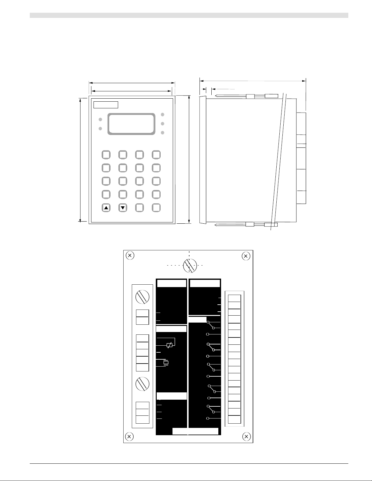
2.1.4. BM90 E/LE Panel mounted converter
The panel mount instrument has two rear screw termi-
nals. There is no serial commnucation connector even on
the BM90 LE
2.1.5. Transducer wiring for BM90E / LE
fig 6
fig 5
10
2.1.6 Transducer Electrical Connections
For BM90 E /LE - Figure 7 below
The panel mount instrument has two-part screw termi-
nals. It can be powered from either an AC or DC supply.
AC power supply - connected: Earth to terminal 1
Neutral to terminal 2
Live to terminal 3
The instrument will automatically accept either 110V or
230V AC –10%, 50Hz or 60Hz, 12VA. A time lag fuse
T160mA is fitted.
DC power supply - connected :
Positive +ve to terminal 10
Negative -ve t o terminal 0v
The instrument will accept 24V DC + 25%, - 10%. 9W.
A time lag fuse T315mA is fitted.
5 SPDT Relays - rated 8A/250V AC/30V DC resistive,
with gold contacts for lower power switching, are connect-
ed to terminals 11 to 25, for activating external alarms,
contactors, pumps etc..
Transducers:
The Level-Sonic BM90 uses RZV15 series transducer.
The Level-Sonic BM90L uses RXV15 series transducer.
Transducer RZV15 and RXV15 - are connected:
Black to terminal 4
Blue to terminal 5
Screen t o terminal 6
Temperature compensated transducer RZT15 and
RXT15 - are connected:
(Screen t o terminal 4
Must enable Pr.37 (Blue to terminal 5
(Black to terminal 8
Isolated Analogue - i s connected :-
Screen t o terminal 26
Positive +ve to terminal 27
Negative -ve t o terminal 28
Separate Temperature Compensation - when compen-
sation is provided by a separate temperature sensor, the
sensor should be connected with a shielded twisted pair
and connected:
(Screen to terminal 6
Must enable Pr.37 (Core* to terminal 7
(Core* to terminal 8
* The polarity of the cores is unimportant, but it is impor -
tant that the screen is connected only at the instrument
end and not at the temperature sensor end.
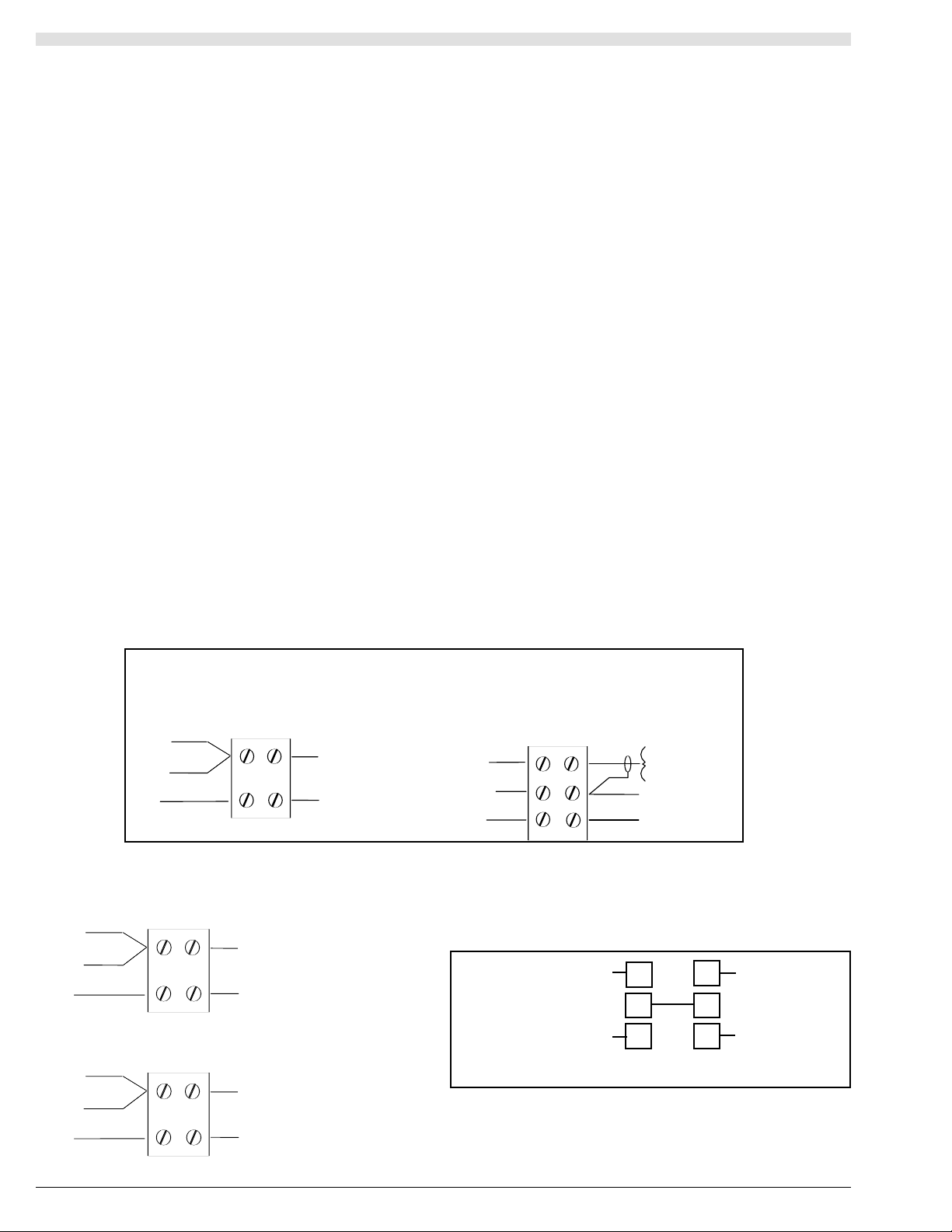
2.1.7 Transducer Cable Extensions for BM90 E / LE
Junction
Screen - Term 4
Standard Transducer
Transceiver
Core - Term 5
Transducer
Black
Screen
Blue
RG62AU
Temperature Compensation Transducer
RG62AU
Blue
Junction
Core -Term.7
Screen - Term.4
Core - Term.5
Screen - Term.4
Transceiver
Transducer
Black
Junction
Screen - Term 4
Transceiver
Core - Term 25
Upstream Transducer
Black
Screen
Blue
RG62AU
Junction
Screen - Term 4
Transceiver
Core - Term 23
Downstream Transducer
Black
Screen
Blue
RG62AU
Transducer cables may be extended using junction boxes as shown in Figure 7 below
fig 7
Transducer wiring for Differential Mode - fig 8
Extend transducer
cable if necessary
with RG62AU as
shown
Link terminals 5
and 24 together
4
23
6
5
24
25
Link
(Without extension cable)
Up & Downstream Sreens
Up & Downstream Blacks
Upstream Blue
Downstream Blue
8
11
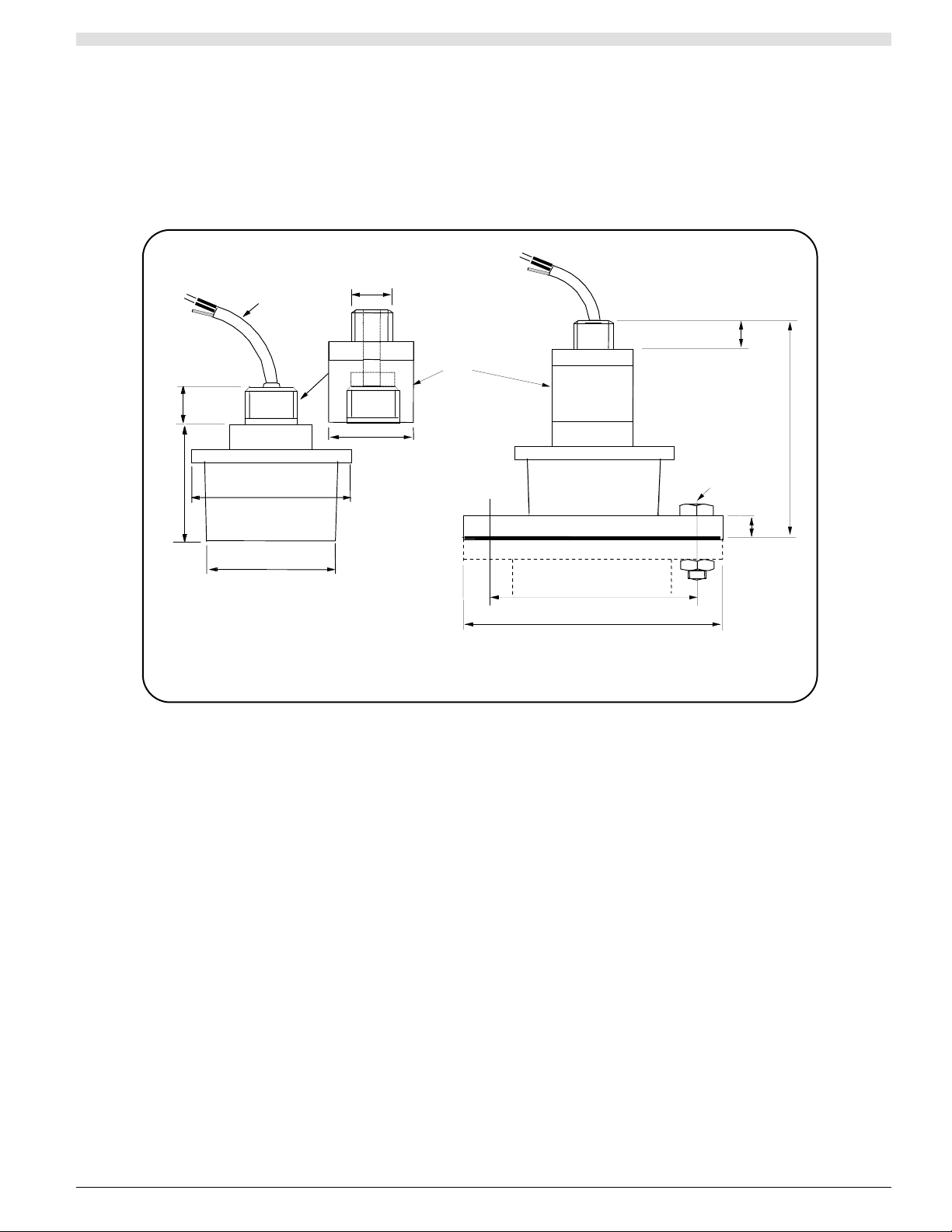
2.2. Transducer Mounting
The transducer can be supplied as ’standard’ or mounted in a Teflon faced flange for applications requiring chemical
compatibility. The figure below shows the dimensions:
20
170
Isolation Kit
Fit as shown
20
21
72
100
10m cable
6.9 dia
50
M20 x 1.5
95
Dia to suit flange selected
No. & size of bolts
to suit flange selected
Bolt hole PCD to suit
flange selected
DIA
DIA
DIA
Standard
Flanged
An isolation kit is provided with each transducer to min-
imise any ringing transmitted through the mounting struc
ture.
The transducer must be mounted perpendicular to the
monitored surface and, ideally, at least 0.5 metres above
it.
The transducer has a 10 inclusive conical beam angle
at 3dB and must be mounted with a clear unobstructed
sight of the liquid to be measured over the complete
measurement range.
The transducer is provided with integral cable which can
be extended up to 300 metres using a suitable junction
box and RG62AU cable. The temperature compensated
transducer requires an additional single core screen
extension.
The extended cable should then be terminated directly
into the instrument.
Transducer cables and temperature compensation
cables can be run together but should be separated from
power cables by at least 150mm and preferably installed
in their own earthed steel conduit.

12
2.2.1. Alternative mounting arrangements for transducer
FLEXIBLE OR RIGID
CONDUIT.
BRACKET.
UNDER FLANGE.
INTEGRAL FLANGE WITH PTFE FACE.
SLIP-ON FLANGE.
ISOLATION KIT.
ISOLATION KIT.
OPTIONAL
ISOLATION KIT
Do not mount transducers incorporating temperature
compensation in direct sunlight.
Do not over-tighten the bolts on flange construction trans-
ducers.
Flange transducers are not pressure rated and are suit-
able only for atmospheric pressure.
CENELEC approved transducers must be mounted and
wired in accordance with the appropriate National
Standards concerning installation in hazardous environ-
ments.
For differential applications mount both transducers at the
same height above the zero datum point.
For open channel flow applications the transducer must
be mounted upstream of the flume or weir as detailed in
BS3680 (usually 3 or 4 times maximum head).
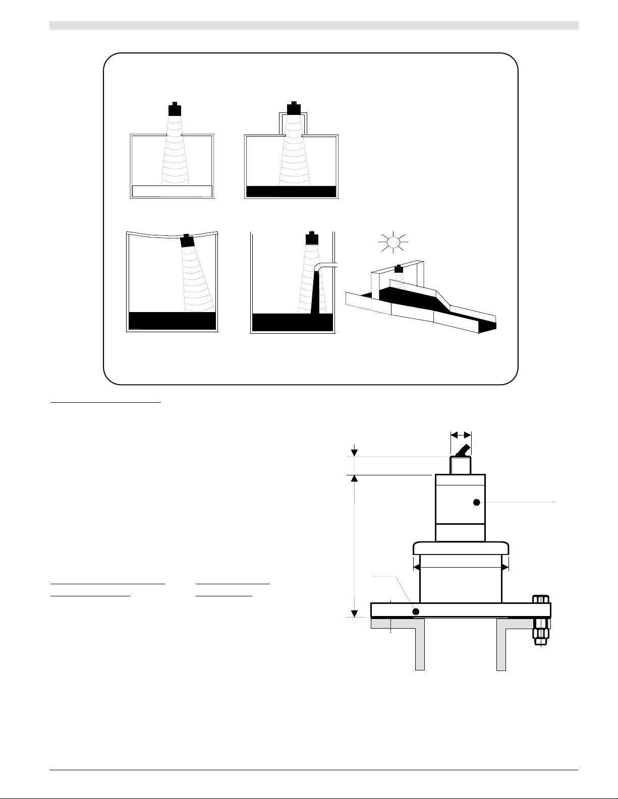
13
KEEP TRANSDUCER
PERPENDICULAR
TO LIQUID.
KEEP TRANSDUCERS AND
TEMPERATURE COMPENSATION
PROBES OUT OF DIRECT
SUNLIGHT
DO NOT AIM THROUGH
HOLES IN THE TANK
.
AVOID ROUGH EDGES
IN STANDPIPES
.
AVOID INFLOWS OR
OTHER OBSTRUCTIONS
.
CAUTION: AVOID THE FOLLOWING TRANSDUCER INSTALLATION FAULTS
Standpipe Installations
In many applications access to a vessel must be made
via a standpipe. However, it is necessary to observe
some basic rules when fitting transducers into stand-
pipes.
BLANKING: Parameter 5 should always be set at
least 150 mm longer than the length of
the standpipe.
STANDPIPE should be in accordance with the follo-
wing table
DIMENSIONS:
Flange size and minimum Maximum length
bore of Standpipe of Standpipe
3" ( 75mm) 300mm
4" (100mm) 300mm
6" (150mm) 400mm
8" (200mm) 600mm
12" (300mm) 600mm
e.g. : Using a 4" flanged transducer would require the
standpipe length to be no more than 300mm and Pr.5 set
at 450 mm minimum.
The inside of the pipe and joint with vessel top must
be clean and free of any obstructions, seams or
welds.
Isolation kit
dia 95 (3.74")
M20 X 1.5
22 (0.86")
155 (6.10")
PVC
flange
 Loading...