

Page 1

Supplementary instructions
Supplementary instructions
OPTIFLEX 4300 C
OPTIFLEX 4300 C
OPTIFLEX 4300 COPTIFLEX 4300 C
Supplementary instructions Supplementary instructions
Guided Radar (TDR) Level Meter for marine applications
Supplementary Instructions for ATEX applications
Supplementary Instructions for ATEX applications
Supplementary Instructions for ATEX applicationsSupplementary Instructions for ATEX applications
© KROHNE 02/2009 - 4000523601 - AD ATEX OPTIFLEX 4300 R01 en
Page 2

CONTENTS
OPTIFLEX 4300 C
1 General safety information 4
1.1 Scope of the document..................................................................................................... 4
1.2 Device description ............................................................................................................ 4
1.3 Standards and approvals.................................................................................................. 4
1.4 Device categories ............................................................................................................. 5
1.5 ATEX nameplates.............................................................................................................. 5
2 Installation 7
2.1 Precautions....................................................................................................................... 7
2.1.1 General notes.......................................................................................................................... 7
2.1.2 Electrostatic discharge........................................................................................................... 7
2.1.3 Special conditions ...................................................................................................................8
2.2 Operating conditions ........................................................................................................ 8
2.2.1 Ambient and flange temperature ...........................................................................................8
2.2.2 Maximum surface temperature of the housing ................................................................... 11
2.2.3 Process pressure.................................................................................................................. 11
3 Electrical connections 12
3.1 General notes ................................................................................................................. 12
3.2 Terminal compartment .................................................................................................. 12
3.2.1 How to open the terminal compartment .............................................................................. 12
3.2.2 How to close the terminal compartment............................................................................. 13
3.3 Terminal tightening capacity.......................................................................................... 13
3.4 Equipotential bonding system........................................................................................ 13
3.5 Ex ia equipment .............................................................................................................. 13
3.5.1 How to connect the electrical cables ................................................................................... 13
3.5.2 Maximum intrinsically-safe values for the electrical circuit............................................... 14
3.5.3 Supply voltage....................................................................................................................... 14
3.5.4 Electrical schema ................................................................................................................. 15
3.6 Ex d [ia] equipment......................................................................................................... 15
3.6.1 General notes........................................................................................................................ 15
3.6.2 How to connect the electrical cables ................................................................................... 16
3.6.3 Supply voltage....................................................................................................................... 17
3.6.4 Electrical schema ................................................................................................................. 17
4 Start-up 18
5 Service 19
5.1 Periodic maintenance..................................................................................................... 19
5.2 Keep the device clean..................................................................................................... 19
5.3 Returning the device to the manufacturer..................................................................... 19
5.3.1 General information.............................................................................................................. 19
5.3.2 Form (for copying) to accompany a returned device............................................................ 20
6 Approval certificate 21
2
www.krohne.com 02/2009 - 4000523601 - AD ATEX OPTIFLEX 4300 R01 en
Page 3

OPTIFLEX 4300 C
CONTENTS
7 Notes 26
www.krohne.com02/2009 - 4000523601 - AD ATEX OPTIFLEX 4300 R01 en
3
Page 4
1 GENERAL SAFETY INFORMATION
1.1 Scope of the document
These instructions are applicable only to the explosion-protection version of the TDR level
transmitter. For all other data, use the Quick Start and other chapters of the Handbook. If you do
not have these documents, please contact the nearest office or download them from the
manufacturer's internet site.
INFORMATION!
The information in this chapter only contains the data applicable to explosion protection. The
technical data for the non-Ex version in the Handbook shall be valid in its current version,
provided that it is not rendered invalid or replaced by this chapter.
WARNING!
Installation, commissioning and maintenance may only be carried out by "Personnel trained in
explosion protection".
1.2 Device description
This device is a 2-wire level transmitter that uses TDR (Time Domain Reflectometry) / Guided
Radar technology. It measures the level, distance, volume and mass of liquids, liquid gases,
pastes, powders, slurries and granular products. It is also suitable for the continuous and
simultaneous measurement of level and interface of 2 liquids. Measurements are displayed via a
DTM (device type manager) for remote communication or an optional integrated display screen
with wizard-driven setup and online help functions.
OPTIFLEX 4300 C
The level transmitter is approved for use in potentially explosive atmospheres when equipped
with the appropriate options.
Ex ia-approved devices can also be equipped with an external sensor to measure process
temperature, pressure, etc.
1.3 Standards and approvals
DANGER!
In compliance with European Directive 94/9/EC (ATEX 100a), the ATEX version of the device
described in these Supplementary Instructions conforms to European Standards EN 600790:2006, EN 60079-1:2007, EN 60079-11:2007, EN 60079-15:2005, EN 60079-26:2007, EN 612410:2006, EN 61241-1:2004 and EN 61241-11:2006. The Ex ia and Ex d [ia] versions are certified for
use in hazardous areas by the KEMA Quality B.V. under KEMA 04ATEX1219 X.
WARNING!
Carefully read the ATEX approval certificate. Obey the boundary conditions.
4
www.krohne.com 02/2009 - 4000523601 - AD ATEX OPTIFLEX 4300 R01 en
Page 5
OPTIFLEX 4300 C
1.4 Device categories
This device is suitable for use in potentially explosive atmospheres of all flammable substances
in Gas Groups IIA, IIB and IIC. It is certified for applications requiring Category 1 G (gases,
vapours or mists), 1 D (dust), 1/2 G, 1/2 D, 2 G or 2 D equipment when fitted with the appropriate
Ex ia options. It is certified for applications requiring Category 1/2G, 1/2D, 2G or 2D equipment
when fitted with the appropriate Ex d options.
INFORMATION!
Category 1
Category 1
Category 1Category 1
The device is installed in hazardous areas requiring Category 1 G or 1 D equipment.
Category 1/2
Category 1/2
Category 1/2Category 1/2
The signal converter is installed in hazardous areas requiring Category 2 G or 2 D equipment.
The probe is installed in hazardous areas requiring Category 1 G or 1 D equipment.
Category 2
Category 2
Category 2Category 2
The device is installed in hazardous areas requiring Category 2 G or 2 D equipment.
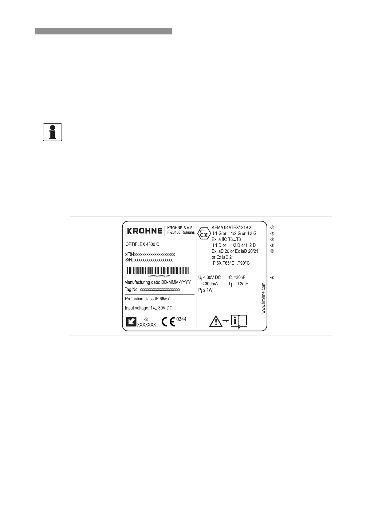
1.5 ATEX nameplates
GENERAL SAFETY INFORMATION 1
Figure 1-1: Ex ia nameplate (device without external sensor)
1 ATEX certification agency code. Refer also to temperature classes
2 Equipment approval categories
3 Types of device protection including approved Gas Groups (IIA, IIB or IIC) and temperature classes for hazardous areas
and maximum surface temperature (please refer to the certificate)
4 Intrinsically-safe circuit data
5 Cable entry type and size (Aluminium housing: M26 x 1.5, M20 x 1.5, ½NPT or G½; Stainless steel housing: M25 x 1.5,
M20 x 1.5, ½NPT or G½)
temperature classes.
temperature classestemperature classes
www.krohne.com02/2009 - 4000523601 - AD ATEX OPTIFLEX 4300 R01 en
5
Page 6
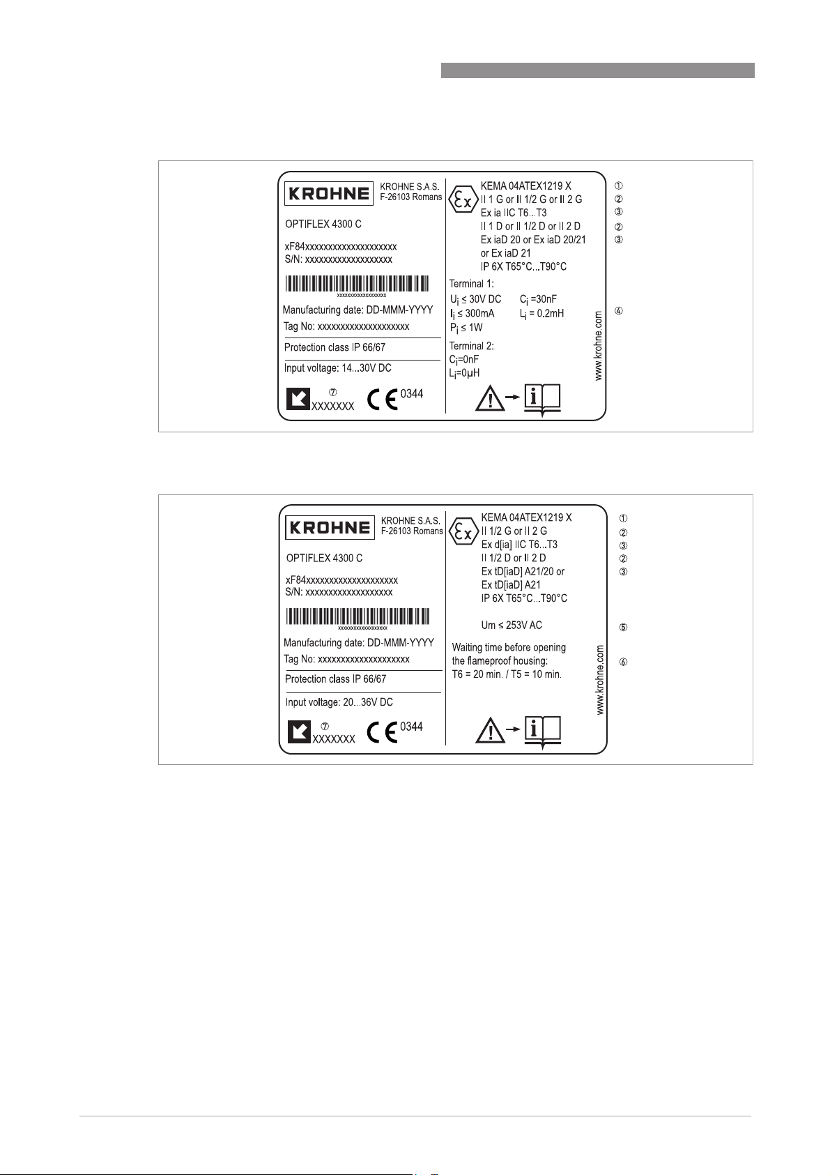
1 GENERAL SAFETY INFORMATION
Figure 1-2: Ex ia nameplate (device with external sensor)
OPTIFLEX 4300 C
Figure 1-3: Ex d[ia] nameplate
1 ATEX certification agency code. Refer also to temperature classes
2 Equipment approval categories
3 Types of device protection including approved Gas Groups (IIA, IIB or IIC) and temperature classes for hazardous areas
and maximum surface temperature (please refer to the certificate)
4 Intrinsically-safe circuit data
5 Maximum voltage in accordance with EN 60079-0
6 Minimum waiting time after power-off before it is safe to open the terminal compartment
7 Cable entry type and size (Aluminium housing: M26 x 1.5, M20 x 1.5, ½NPT or G½; Stainless steel housing: M25 x 1.5,
M20 x 1.5, ½NPT or G½)
6
temperature classes.
temperature classestemperature classes
www.krohne.com 02/2009 - 4000523601 - AD ATEX OPTIFLEX 4300 R01 en
Page 7
OPTIFLEX 4300 C
2.1 Precautions
2.1.1 General notes
WARNING!
When you install the device, obey the conditions in the EC-Type Examination certificate. These
conditions include:
•
The special conditions for safe use.
•
The Essential Health and Safety Requirements.
DANGER!
This installation must agree with EN 60079-14: Electrical installations in hazardous areas.
2.1.2 Electrostatic discharge
DANGER!
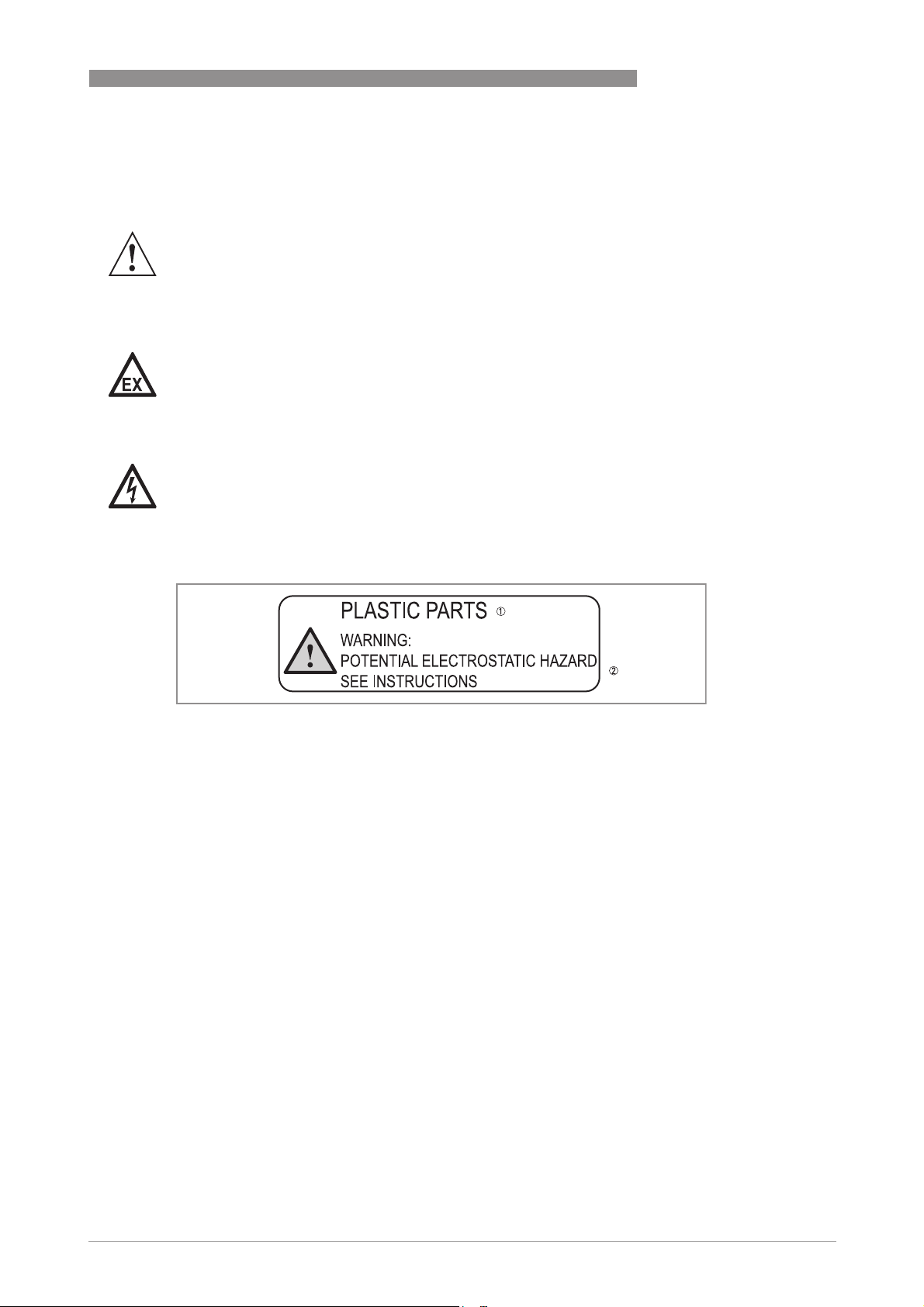
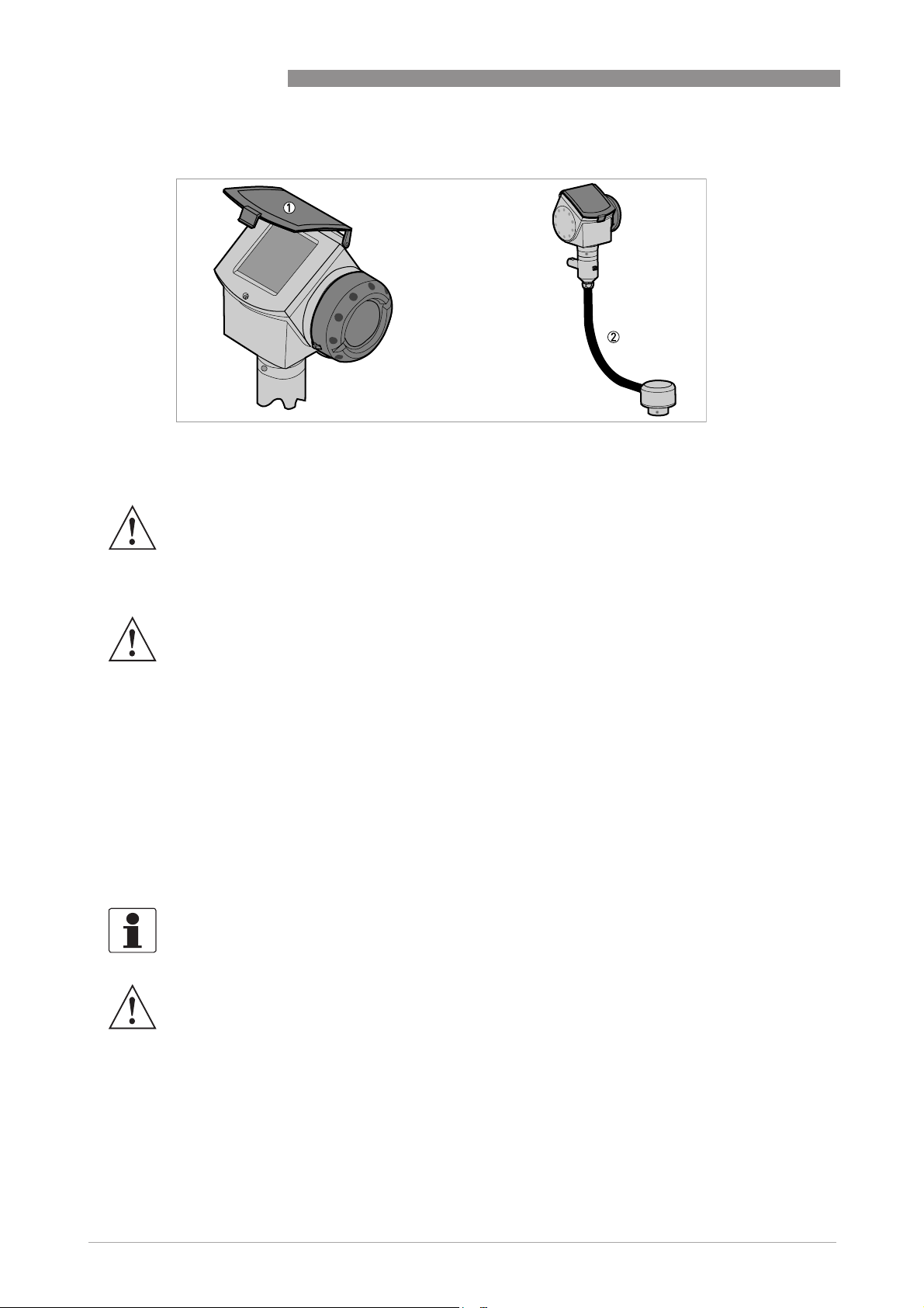
Risk of electrostatic discharge from the blue plastic sun cover, the conduit of the remote housing
option and the optional plastic protective sheath for the single rod probe. Make sure that all
personnel and equipment are correctly grounded.
INSTALLATION 2
Figure 2-1: ESD warning sticker (below the device nameplate)
1 Text: Plastic Parts
2 Text: Warning! Potential electrostatic hazard - see instructions
Take the necessary antistatic precautions if you:
• handle,
• install or
• use
the device in potentially explosive atmospheres. Do not install in a location (near to ventilation
systems, for example) where the electrostatic charge can increase.
www.krohne.com02/2009 - 4000523601 - AD ATEX OPTIFLEX 4300 R01 en
7
Page 8
2 INSTALLATION
Figure 2-2: Risk of ESD: sun cover and remote housing conduit
1 Sun cover
2 Conduit of the remote housing option
WARNING!
FEP-coated single cable probes are for Gas group IIB only.
OPTIFLEX 4300 C
2.1.3 Special conditions
WARNING!
Aluminium housing: Possible source of ignition in a potentially explosive atmosphere. The
housing is made of either aluminium alloy or stainless steel. If the device has an aluminium
alloy housing, make sure that iron/steel objects do not hit or rub against the device.
2.2 Operating conditions
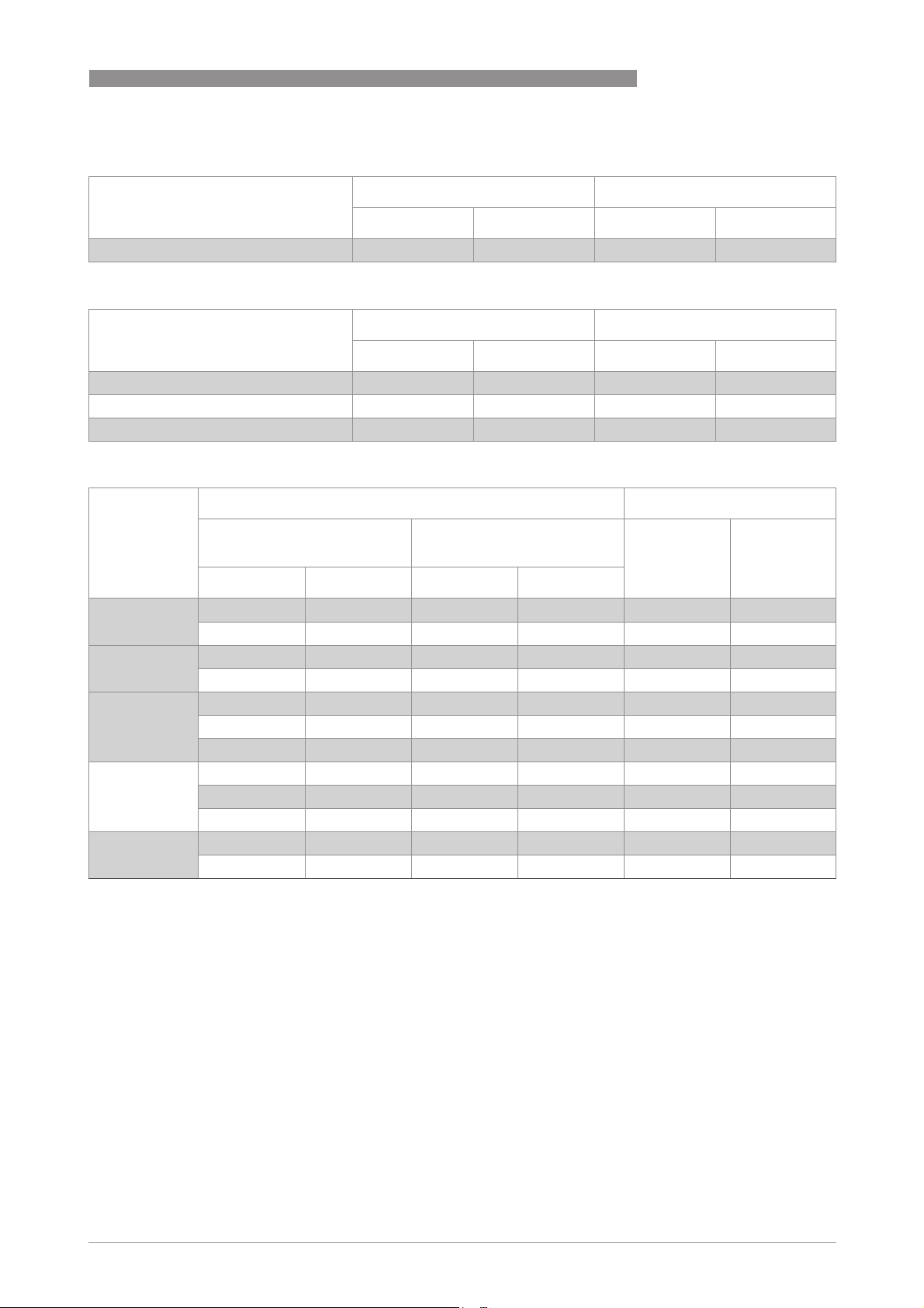
The allowable ambient temperature and corresponding flange temperature range for the device
depends on the ATEX equipment category and temperature classes marked on the nameplate.
2.2.1 Ambient and flange temperature
The ATEX equipment category and temperature class give the ambient temperature and related
flange temperature ranges for the device.
INFORMATION!
The remote converter and Metaglas
WARNING!
The gasket temperature must not be more or less than the approved limits.
®
options use the values that follow.
8
www.krohne.com 02/2009 - 4000523601 - AD ATEX OPTIFLEX 4300 R01 en
Page 9
OPTIFLEX 4300 C
INSTALLATION 2
Equipment category II 1 G (Ex ia devices only)
Temperature class Ambient temperature Flange temperature
[°C] [°F] [°C] [°F]
T6 -20…+60 -4…+140 -20…+60°C -4…+140
Equipment category II 1/2 G
Temperature class Ambient temperature Flange temperature
[°C] [°F] [°C] [°F]
T6 -40…+60 -40…+140 -20…+60°C -4…+140
T5 -40…+75 -40…+167 -20…+60°C -4…+140
T4 -40…+85 -40…+185 -20…+60°C -4…+140
Equipment category II 2 G: Ø2 mm/Ø0.08¨ single cable probe (HT, HP and HT/HP versions)
Temperature
Ambient temperature Flange temperature
class
Ø2 mm/Ø0.08¨ single cable
probe (HT version)
Ø2 mm/Ø0.08¨ single cable
probe (other versions)
[°C] [°F]
[°C] [°F] [°C] [°F]
T6 -40…+60 -40…+140 -40…+60 -40…+140 -50…+60 1 -58…+140 2
-40…+56 -40…+133 -40…+52 -40…+126 -50…+85 1 -58…+185 2
T5 -40…+75 -40…+167 -40…+75 -40…+167 -50…+75 1 -58…+167 2
-40…+71 -40…+160 -40…+67 -40…+153 -50…+100 1 -58…+212 2
T4 -40…+85 -40…+185 -40…+85 -40…+185 -50…+85 1 -58…+185 2
-40…+80 -40…+176 -40…+77 -40…+170 -50…+110 1 -58…+230 2
-40…+77 -40…+170 -40…+70 -40…+158 -50…+135 1 -58…+275 2
T3 -40…+75 -40…+165 -40…+65 -40…+149 -50…+150 1 -58…+302 2
-40…+71 -40…+160 - - -50…+180 1 -58…+356 2
-40…+69 -40…+157 - - -50…+200 1 -58…+392 2
T2 -40…+62 -40…+144 - - -50…+250 1 -58…+482 2
-40…+55 -40…+131 - - -50...+300 1 -58…+572 2
1 -50°C, if an EPDM gasket is used. -40°C, if a Viton® GLT gasket is used. -20°C, if a Kalrez® 6375 gasket is used.
2 -58°F, if an EPDM gasket is used. -40°F, if a Viton® GLT gasket is used. -4°F, if a Kalrez® 6375 gasket is used.
www.krohne.com02/2009 - 4000523601 - AD ATEX OPTIFLEX 4300 R01 en
9
Page 10
2 INSTALLATION
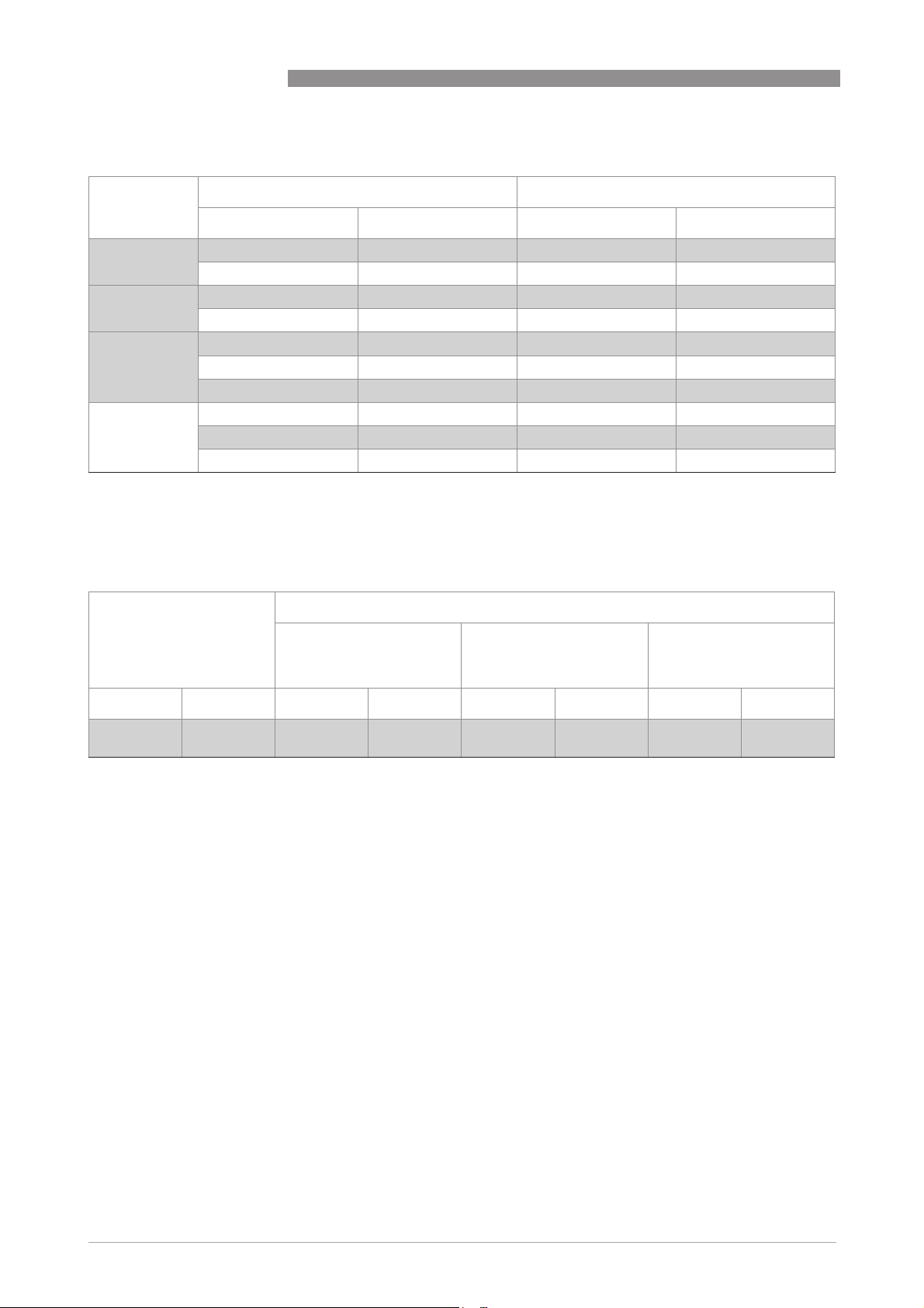
Equipment category II 2 G: all other probe types
OPTIFLEX 4300 C
Temperature
Ambient temperature Flange temperature
class
[°C] [°F] [°C] [°F]
T6 -40…+60 -40…+140 -50…+60 1 -58…+140 2
-40…+55 -40…+131 -50…+85 1 -58…+185 2
T5 -40…+75 -40…+167 -50…+75 1 -58…+167 2
-40…+70 -40…+158 -50…+100 1 -58…+203 2
T4 -40…+85 -40…+185 -50…+85 1 -58…+185 2
-40…+80 -40…+176 -50…+110 1 -58…+230 2
-40…+75 -40…+167 -50…+135 1 -58…+275 2
T3 -40…+70 -40…+158 -50…+150 1 -58…+302 2
-40…+65 3 -40…+149 4 -50…+180 1 -58…+356 2
-40…+60 3 -40…+140 4 -50…+200 1 -58…+392 2
1 -50°C, if an EPDM gasket is used. -40°C, if a Viton® GLT gasket is used. -20°C, if a Kalrez® 6375 gasket is used.
2 -58°F, if an EPDM gasket is used. -40°F, if a Viton® GLT gasket is used. -4°F, if a Kalrez® 6375 gasket is used.
3 if the device has an adaptor for BM 100 probes, the flange temperature must be less than 150°C
4 if the device has an adaptor for BM 100 probes, the flange temperature must be less than 300°F
Equipment category II 1 D (Ex ia devices only), II 1/2 D, and II 2 D
Ambient temperature Flange temperature
Ø2 mm/Ø0.08¨ single
cable probe (HT version)
Ø2 mm/Ø0.08¨ single
cable probe (other
versions)
Other probes
[°C] [°F] [°C] [°F] [°C] [°F] [°C] [°F]
-40…+85 -40…+185 -50…+3001-58…+5722-50…+1501-58…+3022-50…+2001-58…+392
1 min. -50°C, if an EPDM gasket is used. Min. -20°C, if a Kalrez® 6375 gasket is used. Min. -40°C, if a Viton® GLT gasket is used.
Min. -30°C, if a Metaglas® feedthrough is used. Min. -50°C, if a PEI feedthrough is used.
2 min. -58°F, if an EPDM gasket is used. Min. -4°F, if a Kalrez® 6375 gasket is used. Min. -40°F, if a Viton® GLT gasket is used.
Min. -22°F, if a Metaglas® feedthrough is used. Min. -58°F, if a PEI feedthrough is used.
2
10
www.krohne.com 02/2009 - 4000523601 - AD ATEX OPTIFLEX 4300 R01 en
Page 11
OPTIFLEX 4300 C
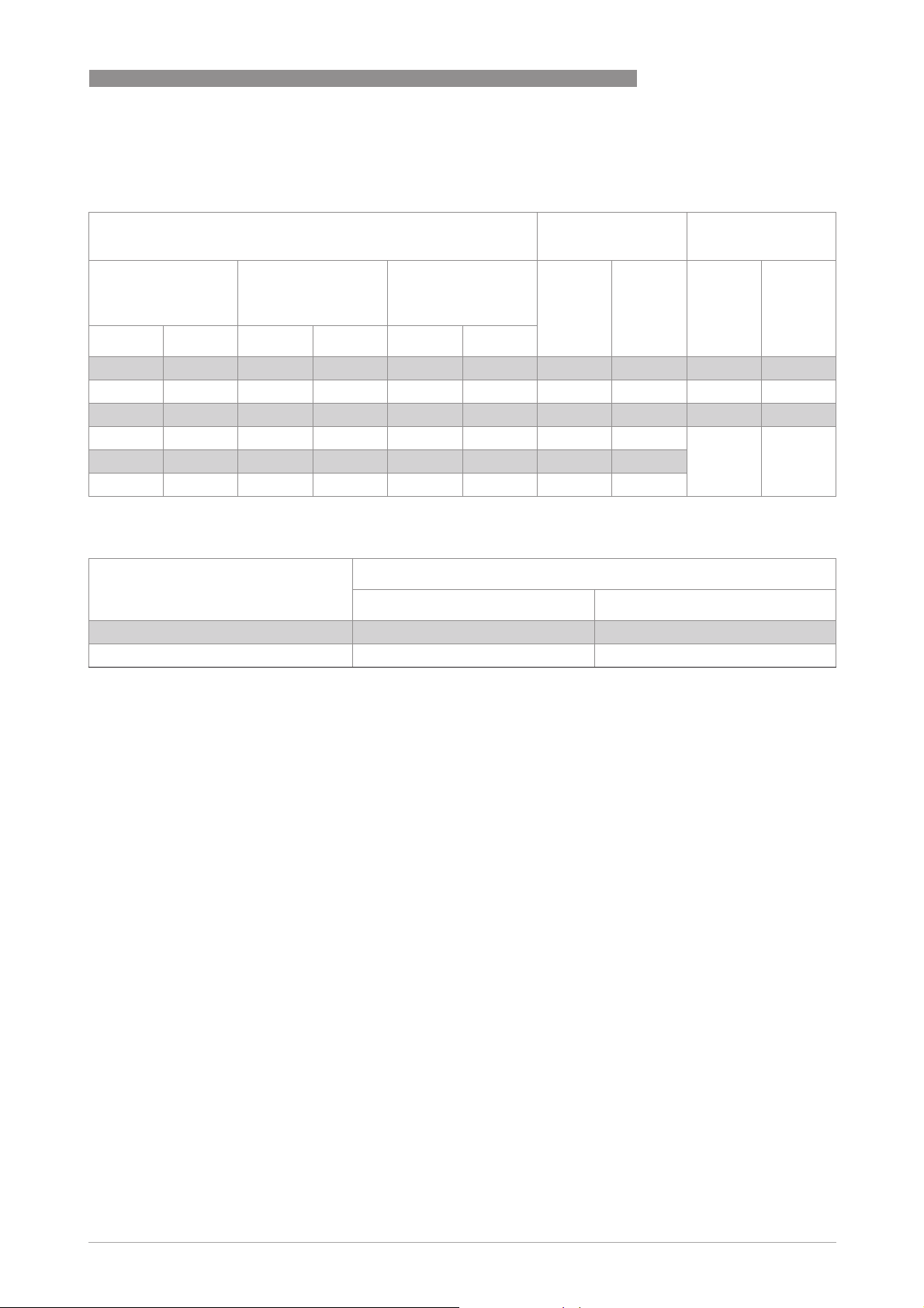
2.2.2 Maximum surface temperature of the housing
Equipment category II 1 D, II 1/2 D, and II 2 D
INSTALLATION 2
Ø2 mm/Ø0.08¨
single cable probe
(HT version)
Max. ambient temperature Max. flange
temperature
Ø2 mm/Ø0.08¨
All other probes [°C] [°F] [°C] [°F]
single cable probe
(other versions)
Max. surface
temperature
[°C] [°F] [°C] [°F] [°C] [°F]
+60 +140 +60 +140 +60 +140 +60 +140 +62 +143
+75 +167 +75 +167 +75 +167 +75 +167 +77 +170
+85 +185 +85 +185 +85 +185 +85 +185 ≤+87 ≤+188
+75 +167 +65 +149 +70 +158 +150 +302 ≤+85 ≤+185
+69 +157 - - +60 +140 +200 +392
+55 +131 - - - - +300 +572
2.2.3 Process pressure
Equipment category Allowable process pressure
[kPa] [psi]
1 G or 1/2 G 80…110 1 11.6…16 1
Others As per non-Ex device As per non-Ex device
1 atmospheric pressure
www.krohne.com02/2009 - 4000523601 - AD ATEX OPTIFLEX 4300 R01 en
11
Page 12
3 ELECTRICAL CONNECTIONS
3.1 General notes
WARNING!
•
De-energize the circuit.
•
Use the applicable cable glands for the cable entry openings in the housing (Aluminium
½
housing: M26 x 1.5, M20 x 1.5,
½
NPT or G½). For the cable entry size, refer to the device nameplate.
•
If ambient temperature >60°C / >140°F, use heat-resistant cables and cable glands certified
for continuous operation above 90
NPT or G½; Stainless steel housing: M25 x 1.5, M20 x 1.5,
°
C / 194°F.
3.2 Terminal compartment
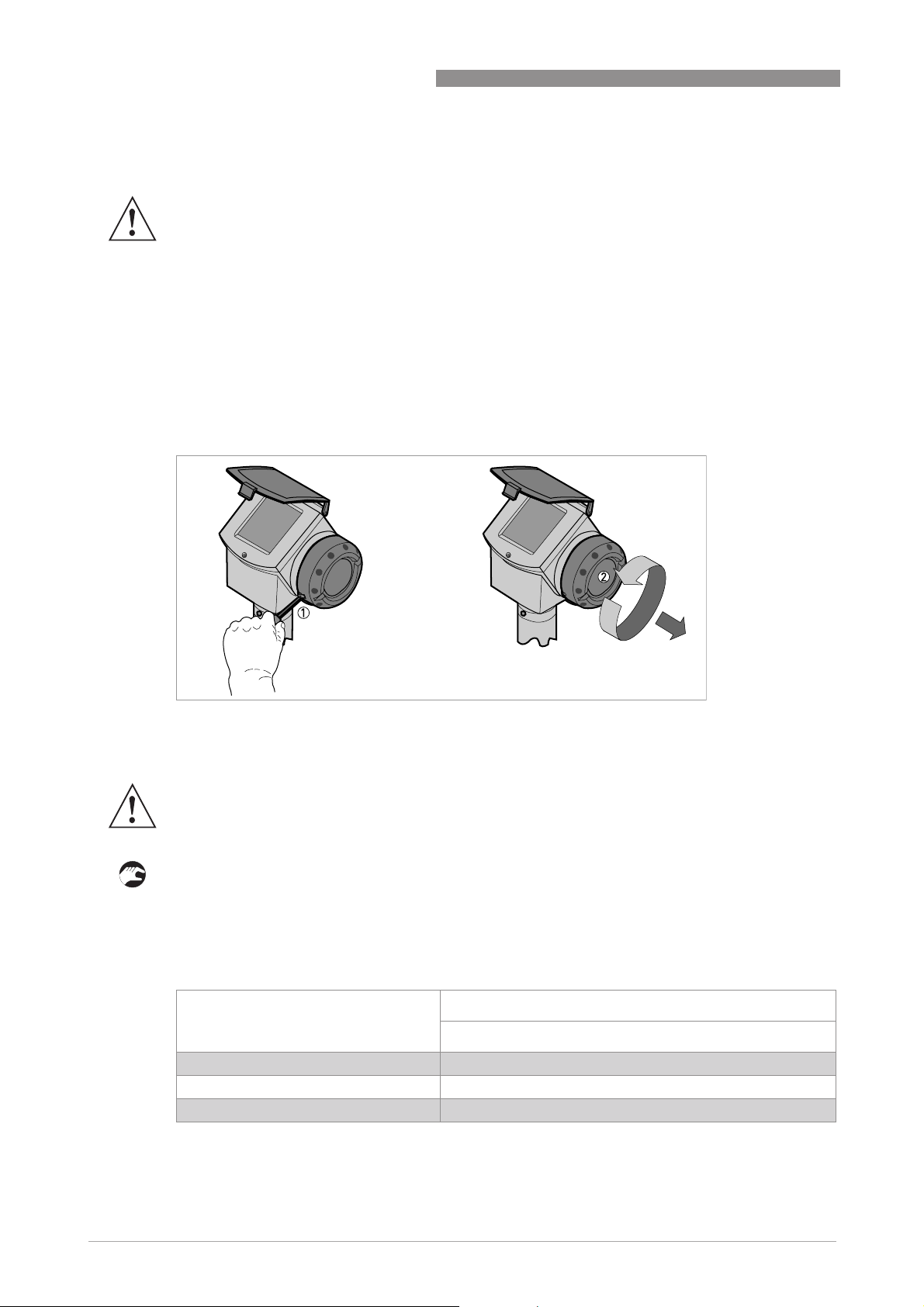
3.2.1 How to open the terminal compartment
OPTIFLEX 4300 C
Figure 3-1: How to open the terminal compartment
1 Cover stop
2 Terminal compartment cover
WARNING!
Do not remove the terminal compartment cover while the electrical power is connected.
• De-energize the circuit.
• After the time given in the table that follows, remove the cover stop 1.
i Use a 3 mm allen wrench.
• Remove the terminal compartment cover 2.
Time necessary to de-energize an Ex d [ia]-approved device
Temperature class Time to de-energize the Ex d [ia]-approved device
[minutes]
T6 20
T5 10
T4, T3 Not necessary
12
www.krohne.com 02/2009 - 4000523601 - AD ATEX OPTIFLEX 4300 R01 en
Page 13
OPTIFLEX 4300 C
3.2.2 How to close the terminal compartment
WARNING!
Ex d [ia] applications: obey the instructions that follow:
• Attach the terminal compartment cover 2.
i Turn the terminal compartment cover carefully to prevent damage to the thread and the
gasket.
• Make sure that the terminal compartment cover is tight.
• Attach the cover stop 1.
i Use a 3 mm allen wrench.
• Make sure that the cover stop 1 screw is tight.
3.3 Terminal tightening capacity
The terminal tightening capacity for curent output terminals 1 and 2 is:
ELECTRICAL CONNECTIONS 3
Type of wire Terminal tightening capacity
Rigid 4 0.0062
Flexible 2.5 0.0039
3.4 Equipotential bonding system
There is a terminal in the terminal compartment and another on the side of the converter
support pillar that can be used equipotential bonding conductors.
3.5 Ex ia equipment
3.5.1 How to connect the electrical cables
INFORMATION!
•
Cable entries are supplied on customer demand. If you supply the cable entries, this part
must have a degree of ingress protection IP≥6x (EN 60529).
• Use the electrical connection procedure in the Handbook.
• If possible, use galvanically-isolated equipment.
• Supply the Ex i equipment connected to the device. Use only certified intrinsically-safe
equipment.
• Connect only to separate certified, intrinsically-safe circuits. Make sure that the electrical
circuit characteristics are not more than the values that follow.
[mm²] [inches²]
www.krohne.com02/2009 - 4000523601 - AD ATEX OPTIFLEX 4300 R01 en
13
Page 14

3 ELECTRICAL CONNECTIONS
3.5.2 Maximum intrinsically-safe values for the electrical circuit
Level transmitter without external sensor (output terminal 1 or 2)
• Ui ≤30 V
≤300 mA
• I
i
≤1W
• P
i
=30 nF
• C
i
=0.2 mH
• L
i
Level transmitter with external sensor: output terminal 1
• Ui ≤30 V
≤300 mA
• I
i
≤1W
• P
i
=30 nF
• C
i
=0.2 mH
• L
i
OPTIFLEX 4300 C
Level transmitter with external sensor: output terminal 2
• Ci =0 nF
=0 mH
• L
i
3.5.3 Supply voltage
Level transmitter without external sensor
Current output terminal Minimum voltage at output
2 (US2) 2 10 1 30 1
1 for a current output of 22 mA
2 use a second power supply. This power supply energizes current output terminal 2 only.
Level transmitter with external sensor
Current output terminal Minimum voltage at output
2 (US2) 2
1 for a current output of 22 mA
2 use a second power supply. This power supply energizes current output terminal 2 only.
3 for more data, refer to the data sheet for the external sensor
Maximum voltage at output
terminal [VDC]
1 (US1) 14 1 30 1
terminal [VDC]
Maximum voltage at output
terminal [VDC]
1 (US1) 14 1 30 1
3 3
terminal [VDC]
14
www.krohne.com 02/2009 - 4000523601 - AD ATEX OPTIFLEX 4300 R01 en
Page 15
OPTIFLEX 4300 C
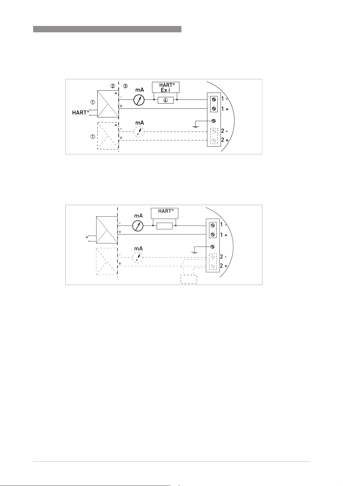
3.5.4 Electrical schema
Without an external sensor
Figure 3-2: Electrical schema for Ex i-approved equipment without an external sensor
1 Intrinsically-safe power supply (use second power supply for optional terminal 2)
2 Non-Ex zone
3 Ex zone
4 Resistor for HART
®
communication
ELECTRICAL CONNECTIONS 3
With an external sensor
2
1
HART
1
Figure 3-3: Electrical schema for Ex i-approved equipment with an external sensor
1 Intrinsically-safe power supply (use second power supply for optional terminal 2)
2 Non-Ex zone
3 Ex zone
4 Resistor for HART
5 External sensor
®
communication
3.6 Ex d [ia] equipment
3.6.1 General notes
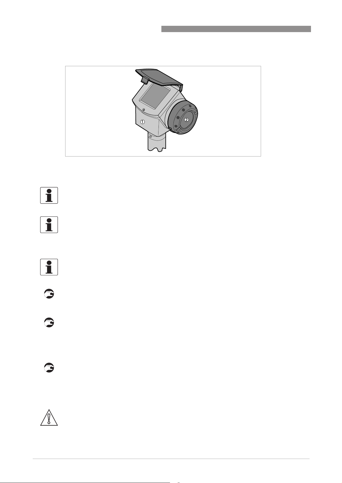
Ex d [ia]-approved equipment have two separate compartments. The electronics in the
electronics block compartment are Ex ia-approved and the terminals compartment is Ex dapproved.
3
=
Ex i
4
=
5
www.krohne.com02/2009 - 4000523601 - AD ATEX OPTIFLEX 4300 R01 en
15
Page 16
3 ELECTRICAL CONNECTIONS
Figure 3-4: Compartments in Ex d [ia]-approved equipment
1 Electronics block (Ex ia) compartment
2 Terminal (Ex d) compartment
INFORMATION!
If you must open the electronics block compartment and remove the electronics blocks for
servicing, it is not necessary to disconnect the wires in the Ex d compartment.
OPTIFLEX 4300 C
INFORMATION!
The flamepath dimensions are better than the values specified in the European Standard
EN 60079-1 (minimum length 14.5 mm and maximum gap 118
3.6.2 How to connect the electrical cables
INFORMATION!
Cable entries are supplied on customer demand. If you supply the cable entries, this part must
have a degree of ingress protection IP≥6x (EN 60529).
• Use only flameproof and Ex d-approved cable entries and plugs.
• If you use only one cable entry, seal the other one with an Ex d-approved plug.
• All Ex d-approved installations must agree with European standards EN 60079-1.
Conduit entries
• Connect the device to an Ex d-approved conduit system.
• Install the applicable Ex d-approved sealing device. It must be installed adjacent to the
housing. For further information, refer to European Standard EN 60079-1.
• If you use only one cable entry, seal the other one with an Ex d-approved plug.
Load resistor
• Connect the load resistor to the positive terminal of the power supply
• Ground the negative connection.
• If the load resistor has to be connected to the negative terminal, the loop resistance must not
be more than 250 ohms.
µ
m).
16
CAUTION!
Do not ground the positive connection.
www.krohne.com 02/2009 - 4000523601 - AD ATEX OPTIFLEX 4300 R01 en
Page 17
OPTIFLEX 4300 C
3.6.3 Supply voltage
ELECTRICAL CONNECTIONS 3
Current output terminal Minimum voltage at output
1 (US1) 20 1 36 1
2 (US2) 2 10 1 30 1
1 for a current output of 22 mA
2 use a second power supply. This power supply energizes current output terminal 2 only.
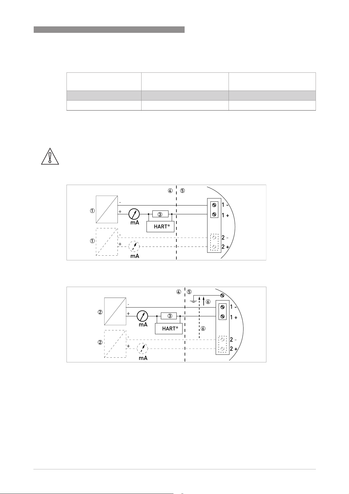
3.6.4 Electrical schema
CAUTION!
Make sure that you connect the load resistor to the positive side.
terminal [VDC]
Maximum voltage at output
terminal [VDC]
Figure 3-5: Electrical schema for Ex d [ia]-approved equipment (with galvanic isolation)
Figure 3-6: Electrical schema for Ex d [ia]-approved equipment (without galvanic isolation)
1 Galvanically-isolated power supply (use a second power supply for optional terminal 2)
2 Power supply (use a second power supply for optional terminal 2)
3 Resistor for HART
4 Non-Ex zone
5 Ex zone
6 |U| < 5 V
®
communication
www.krohne.com02/2009 - 4000523601 - AD ATEX OPTIFLEX 4300 R01 en
17
Page 18

4 START-UP
WARNING!
Make sure that it is safe to supply electrical power. Do a start-up check:
• Are the wetted components (gasket, flange and probe) resistant to corrosion by the tank
product?
• Does the information given on the nameplate agree with the application?
• Did you connect the equipotential bonding system correctly?
• Ex d applications:
Ex d applications: Are the cable entries, plugs and adaptors Ex d-approved?
Ex d applications:Ex d applications:
• Ex i applications:
Ex i applications: Are you using an intrinsically-safe barrier within the correct parameters?
Ex i applications:Ex i applications:
refer to
than the maximum intrinsically-safe values.
• Did you install the correct cable entries? Is the terminal compartment correctly sealed?
Ex ia equipment
OPTIFLEX 4300 C
on page 13. The electrical circuit characteristics must not be more
18
www.krohne.com 02/2009 - 4000523601 - AD ATEX OPTIFLEX 4300 R01 en
Page 19
OPTIFLEX 4300 C
5.1 Periodic maintenance
No maintenance is necessary.
5.2 Keep the device clean
WARNING!
Do not let more than 5 mm / 0.2
of ignition in a potentially explosive atmosphere.
DANGER!
Risk of electrostatic discharge from the plastic sun cover and the conduit of the remote housing
option.
Obey these instructions:
• Keep the thread of the terminal compartment cover clean.
• If dirt collects on the device, clean it. Wipe the plastic sun cover with a damp cloth.
SERVICE 5
¨
of dust collect on the top of the device. This is a possible source
5.3 Returning the device to the manufacturer
5.3.1 General information
This device has been carefully manufactured and tested. If installed and operated in accordance
with these operating instructions, it will rarely present any problems.
CAUTION!
Should you nevertheless need to return a device for inspection or repair, please pay strict
attention to the following points:
•
Due to statutory regulations on environmental protection and safeguarding the health and
safety of our personnel, manufacturer may only handle, test and repair returned devices that
have been in contact with products without risk to personnel and environment.
•
This means that the manufacturer can only service this device if it is accompanied by the
following certificate (see next section) confirming that the device is safe to handle.
CAUTION!
If the device has been operated with toxic, caustic, flammable or water-endangering products,
you are kindly requested:
•
to check and ensure, if necessary by rinsing or neutralizing, that all cavities are free from
such dangerous substances,
•
to enclose a certificate with the device confirming that is safe to handle and stating the
product used.
www.krohne.com02/2009 - 4000523601 - AD ATEX OPTIFLEX 4300 R01 en
19
Page 20
5 SERVICE
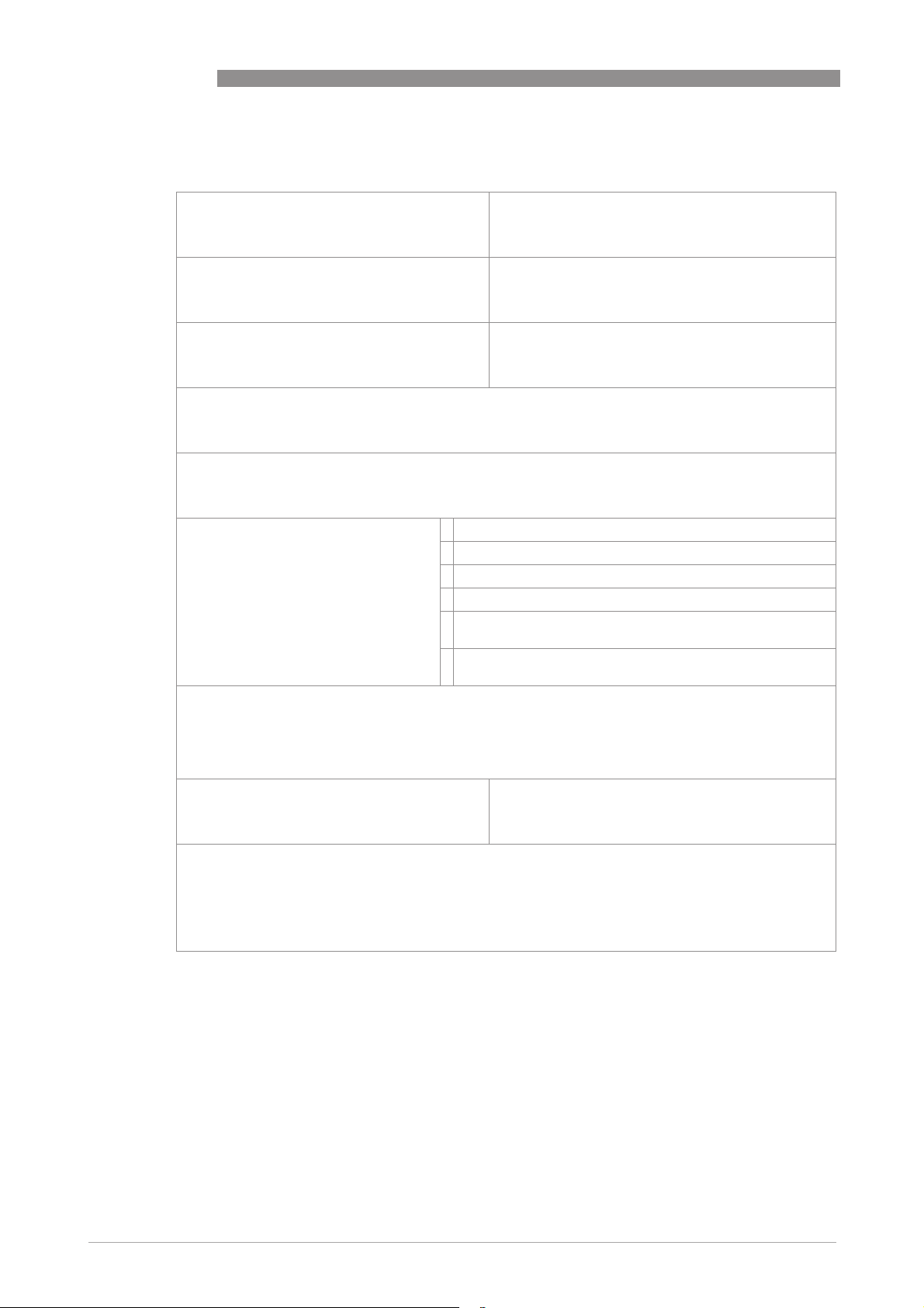
5.3.2 Form (for copying) to accompany a returned device
Company: Address:
Department: Name:
Tel. no.: Fax no.:
Manufacturer's order no. or serial no.:
The device has been operated with the following medium:
OPTIFLEX 4300 C
This medium is: water-hazardous
toxic
caustic
flammable
We checked that all cavities in the device are free from such
substances.
We have flushed out and neutralized all cavities in the
device.
We hereby confirm that there is no risk to persons or the environment through any residual media
contained in the device when it is returned.
Date: Signature:
Stamp:
20
www.krohne.com 02/2009 - 4000523601 - AD ATEX OPTIFLEX 4300 R01 en
Page 21

OPTIFLEX 4300 C
APPROVAL CERTIFICATE 6
Figure 6-1: ATEX certificate, page 1 of 5
www.krohne.com02/2009 - 4000523601 - AD ATEX OPTIFLEX 4300 R01 en
21
Page 22

6 APPROVAL CERTIFICATE
OPTIFLEX 4300 C
22
Figure 6-2: ATEX certificate, page 2 of 5
www.krohne.com 02/2009 - 4000523601 - AD ATEX OPTIFLEX 4300 R01 en
Page 23

OPTIFLEX 4300 C
APPROVAL CERTIFICATE 6
Figure 6-3: ATEX certificate, page 3 of 5
www.krohne.com02/2009 - 4000523601 - AD ATEX OPTIFLEX 4300 R01 en
23
Page 24

6 APPROVAL CERTIFICATE
OPTIFLEX 4300 C
24
Figure 6-4: ATEX certificate, page 4 of 5
www.krohne.com 02/2009 - 4000523601 - AD ATEX OPTIFLEX 4300 R01 en
Page 25

OPTIFLEX 4300 C
APPROVAL CERTIFICATE 6
Figure 6-5: ATEX certificate, page 5 of 5
www.krohne.com02/2009 - 4000523601 - AD ATEX OPTIFLEX 4300 R01 en
25
Page 26

7 NOTES
OPTIFLEX 4300 C
26
www.krohne.com 02/2009 - 4000523601 - AD ATEX OPTIFLEX 4300 R01 en
Page 27

OPTIFLEX 4300 C
NOTES 7
www.krohne.com02/2009 - 4000523601 - AD ATEX OPTIFLEX 4300 R01 en
27
Page 28
KROHNE product overview
• Electromagnetic flowmeters
• Variable area flowmeters
• Ultrasonic flowmeters
• Mass flowmeters
• Vortex flowmeters
• Flow controllers
• Level meters
• Temperature meters
• Pressure meters
• Analysis products
• Measuring systems for the oil and gas industry
• Measuring systems for sea-going tankers
Head Office KROHNE Messtechnik GmbH & Co. KG
Ludwig-Krohne-Str. 5
D-47058 Duisburg (Germany)
Tel.:+49 (0)203 301 0
Fax:+49 (0)203 301 10389
[email protected]
© KROHNE 02/2009 - 4000523601 - AD ATEX OPTIFLEX 4300 R01 en - Subject to change without notice.
The current list of all KROHNE contacts and addresses can be found at:
www.krohne.com
 Loading...