


 H250 M40 Handbook
Variable area flowmeter
© KROHNE 10/2018 - 4000640705 - MA H250-M40 R05 en
:IMPRINT :::::::::::::::::::::::::::::::::::::::
All rights reserved. It is prohibited to reproduce this documentation, or any part thereof, without the prior written authorisation of KROHNE Messtechnik GmbH.
Subject to change without notice.
Copyright 2018 by
KROHNE Messtechnik GmbH - Ludwig-Krohne-Str. 5 - 47058 Duisburg (Germany)
2 |
www.krohne.com |
10/2018 - 4000640705 - MA H250-M40 R05 en |

|
|
|
|
CONTENTS |
|
|
|
|
H250 M40 |
|
|
||||
|
|
|
|
|
|
||
1 |
Safety instructions |
5 |
|
||||
|
|
|
|
|
|
|
|
|
|
|
1.1 |
Intended use ..................................................................................................................... |
5 |
|
|
|
|
|
1.2 |
Certifications .................................................................................................................... |
6 |
|
|
|
|
|
1.3 |
Pressure equipment directive.......................................................................................... |
6 |
|
|
|
|
|
1.4 |
Safety instructions from the manufacturer ..................................................................... |
8 |
|
|
|
|
|
1.4.1 Copyright and data protection ................................................................................................ |
8 |
|
||
|
|
|
1.4.2 Disclaimer ............................................................................................................................... |
8 |
|
||
|
|
|
1.4.3 Product liability and warranty ................................................................................................ |
9 |
|
||
|
|
|
1.4.4 Information concerning the documentation........................................................................... |
9 |
|
||
|
|
|
1.4.5 Warnings and symbols used................................................................................................. |
10 |
|
||
|
|
|
1.5 |
Safety instructions for the operator............................................................................... |
10 |
|
|
|
|
2 Device description |
11 |
|
|||
|
|
|
|
|
|
|
|
|
|
|
2.1 |
Scope of delivery............................................................................................................. |
11 |
||
|
|
|
2.2 |
Device version................................................................................................................. |
12 |
||
|
|
|
2.2.1 Indicator versions ................................................................................................................. |
13 |
|
||
|
|
|
2.2.2 Float damping ....................................................................................................................... |
15 |
|
||
|
|
|
2.2.3 Pointer damping.................................................................................................................... |
15 |
|
||
|
|
|
2.3 |
Nameplate ...................................................................................................................... |
16 |
||
|
|
|
2.4 |
Description code............................................................................................................. |
17 |
||
|
|
|
2.5 |
Electronic revision.......................................................................................................... |
18 |
||
3 |
Installation |
19 |
|
||||
|
|
|
|
|
|
|
|
|
|
|
3.1 |
General installation notes .............................................................................................. |
19 |
|
|
|
|
|
3.2 |
Storage ........................................................................................................................... |
19 |
||
|
|
|
3.3 |
Installation conditions .................................................................................................... |
20 |
||
|
|
|
3.3.1 Tightening torques................................................................................................................ |
22 |
|
||
|
|
|
3.3.2 Magnetic filters ..................................................................................................................... |
22 |
|
||
|
|
|
3.3.3 Heat insulation ...................................................................................................................... |
23 |
|
||
|
|
4 Electrical connections |
24 |
|
|||
|
|
|
|
|
|
||
|
|
|
4.1 |
Safety instructions.......................................................................................................... |
24 |
||
|
|
|
4.2 |
Electrical connection for indicator M40 ......................................................................... |
25 |
|
|
|
|
|
4.2.1 Connection of the limit switches K1/K2................................................................................ |
25 |
|||
|
|
|
4.2.2 Current output ESK4 / ESK4A............................................................................................... |
28 |
|
||
|
|
|
4.2.3 ESK4-T limit outputs............................................................................................................. |
31 |
|
||
|
|
|
4.2.4 ESK4-T pulse output ............................................................................................................. |
33 |
|
||
|
|
|
4.2.5 ESK4-T binary input .............................................................................................................. |
34 |
|
||
|
|
|
4.2.6 ESK4-FF / ESK4-PA fieldbus communication...................................................................... |
35 |
|
||
|
|
|
4.2.7 Harting HAN 7D connection.................................................................................................. |
36 |
|
||
|
|
|
4.3 |
Grounding connections................................................................................................... |
37 |
|
|
|
|
|
4.4 |
Ingress protection .......................................................................................................... |
37 |
||
10/2018 - 4000640705 - MA H250-M40 R05 en |
www.krohne.com |
3 |

|
CONTENTS |
H250 M40 |
|
|
|
||
|
|
|
|
5 Start-up |
|
38 |
|
|
|
|
|
5.1 |
Standard device .............................................................................................................. |
38 |
|
5.2 |
Indicator ESK4-T ............................................................................................................ |
38 |
|
6 Operation |
|
39 |
|
|
|
|
|
6.1 |
ESK4 / ESK4A - Loop Check Mode ................................................................................. |
39 |
|
6.2 |
Operating elements ESK4-T........................................................................................... |
40 |
|
6.3 |
Basic principles of operation ESK4-T ............................................................................ |
41 |
|
6.3.1 Description of the operating keys......................................................................................... |
41 |
||
6.3.2 Navigation within the menu structure.................................................................................. |
41 |
||
6.3.3 Change the settings in the menu.......................................................................................... |
42 |
||
6.4 |
Overview of the units ESK4-T......................................................................................... |
43 |
|
6.5 |
Error messages ESK4-T................................................................................................. |
44 |
|
6.6 |
ESK4-T menu.................................................................................................................. |
46 |
|
6.6.1 Factory settings .................................................................................................................... |
46 |
||
6.6.2 Menu structure ..................................................................................................................... |
47 |
||
6.6.3 Menu description .................................................................................................................. |
49 |
||
7 Service |
|
56 |
|
|
|
|
|
7.1 |
Maintenance ................................................................................................................... |
56 |
|
7.2 |
Replacement and retrofitting......................................................................................... |
56 |
|
7.2.1 Replacing floats .................................................................................................................... |
56 |
||
7.2.2 |
Retrofitting of the float damping .......................................................................................... |
57 |
|
7.2.3 |
Retrofitting of the limit switch .............................................................................................. |
58 |
|
7.2.4 Replacement - Retrofitting ESK4 / ESK4A ........................................................................... |
59 |
||
7.2.5 Replacement - Retrofitting add-on module ESK4-T / PA / FF............................................. |
60 |
||
7.3 |
Spare parts availability................................................................................................... |
60 |
|
7.3.1 List of spare parts................................................................................................................. |
60 |
||
7.4 |
Availability of services .................................................................................................... |
64 |
|
7.5 |
Returning the device to the manufacturer..................................................................... |
64 |
|
7.5.1 General information.............................................................................................................. |
64 |
||
7.5.2 Form (for copying) to accompany a returned device............................................................ |
65 |
||
7.6 |
Disposal .......................................................................................................................... |
65 |
|
7.7 |
Disassembly and recycling............................................................................................. |
66 |
|
7.7.1 Description of the device components ................................................................................. |
66 |
||
7.7.2 |
Indicator versions ................................................................................................................. |
67 |
|
8 Technical data |
70 |
||
|
|
|
|
8.1 |
Functional principle........................................................................................................ |
70 |
|
8.2 |
Technical data................................................................................................................. |
71 |
|
8.3 |
Dimensions and weight .................................................................................................. |
79 |
|
8.4 |
Measuring ranges........................................................................................................... |
82 |
|
9 Notes |
|
|
90 |
|
|
|
|
4 |
www.krohne.com |
10/2018 - 4000640705 - MA H250-M40 R05 en |
|
|
SAFETY INSTRUCTIONS 1 |
|
H250 M40 |
|
|
|
|
1.1 Intended use
CAUTION!
Responsibility for the use of the measuring devices with regard to suitability, intended use and corrosion resistance of the used materials against the measured fluid lies solely with the operator.
INFORMATION!
This device is a Group 1, Class A device as specified within CISPR11:2009. It is intended for use in industrial environment. There may be potential difficulties in ensuring electromagnetic compatibility in other environments, due to conducted as well as radiated disturbances.
INFORMATION!
The manufacturer is not liable for any damage resulting from improper use or use for other than the intended purpose.
The variable area flowmeters are suitable for measuring clean gases, vapours and liquids.
Intended use:
•The product may not contain any ferromagnetic particles or solids. It may be necessary to install magnetic filters or mechanical filters.
•The product must be sufficiently liquid and free of deposits.
•Avoid pressure surges and pulsing flows.
•Open valves slowly. Do not use solenoid valves.
Use suitable measures to eliminate compression vibrations during gas measurements:
•Short pipeline lengths to next restriction
•Nominal pipe size not greater than nominal device size
•Use of floats with damping
•Increase in operating pressure (while taking into account the resulting change in density and thus change in scale)
Observe installation conditions according to VDI/VDE 3513-3.
DANGER!
For devices used in hazardous areas, additional safety notes apply; please refer to the Ex documentation.
CAUTION!
Do not use any abrasive media containing solid particles or highly viscous media.
10/2018 - 4000640705 - MA H250-M40 R05 en |
www.krohne.com |
5 |

1 SAFETY INSTRUCTIONS |
|
|
H250 M40 |
|
|
|
|
|
1.2 Certifications
CE marking
The device fulfils all applicable statutory requirements of the EU directives:
•Pressure equipment directive
•For devices with electrical installations: EMC directive
•Devices for use in hazardous areas: ATEX directive
as well as
• NAMUR recommendations NE 21, NE 43 and NE 107
The manufacturer certifies successful testing of the product by applying the CE marking. An EU declaration of conformity regarding the directives in question and the associated harmonised standards can be downloaded from our internet site.
1.3 Pressure equipment directive
A conformity assessment in accordance with pressure equipment directive has been carried out for the devices described. Conformity is certified by applying the CE mark. The number of the notified body is also stated.
The PED key describes the rating of the devices:
Example: PED/G1/III/H
G |
Gases and vapours |
1 |
Fluid group 1 |
III |
Category III |
H |
Conformity assessment method according to Module H |
The PED key identification can be found on the nameplate of the device (for details refer to
Nameplate on page 16).
INFORMATION!
The stated pressures (PS) and temperatures (TS) only apply as refers to the pressure resistance of the sensor body. As regards the functionality of the entire device, further restrictions of the maximum temperature may need to be observed (e.g. ATEX approval). Devices rated below category I due to their size, do not receive the CE mark in the scope of the PED. These devices are subject to applicable sound engineering practice (SEP).
6 |
www.krohne.com |
10/2018 - 4000640705 - MA H250-M40 R05 en |

|
|
SAFETY INSTRUCTIONS 1 |
|
H250 M40 |
|
|
|
|
Residual risk
A risk analysis in accordance with the pressure equipment directive has been carried out for the devices . The residual risk is described as follows:
•The devices are designed according to the valid and applicable rules and standards for static operation and their pressure resistance is calculated for the declared maximum pressure and temperature (no calculation for cyclical change).
•Responsibility for the use of the measuring devices with regard to corrosion resistance of the used materials against the measured fluid lies solely with the operator.
•Avoid abrasion.
•Avoid pulsation and cavitation.
•Protect devices from vibration and high-frequency oscillation.
•Draining (backflow) may be delayed due to the float in the measuring tube.
•Implement appropriate measures to counteract external fire hazards
10/2018 - 4000640705 - MA H250-M40 R05 en |
www.krohne.com |
7 |

1 SAFETY INSTRUCTIONS |
|
|
H250 M40 |
|
|
|
|
|
1.4 Safety instructions from the manufacturer
1.4.1 Copyright and data protection
The contents of this document have been created with great care. Nevertheless, we provide no guarantee that the contents are correct, complete or up-to-date.
The contents and works in this document are subject to copyright. Contributions from third parties are identified as such. Reproduction, processing, dissemination and any type of use beyond what is permitted under copyright requires written authorisation from the respective author and/or the manufacturer.
The manufacturer tries always to observe the copyrights of others, and to draw on works created in-house or works in the public domain.
The collection of personal data (such as names, street addresses or e-mail addresses) in the manufacturer's documents is always on a voluntary basis whenever possible. Whenever feasible, it is always possible to make use of the offerings and services without providing any personal data.
We draw your attention to the fact that data transmission over the Internet (e.g. when communicating by e-mail) may involve gaps in security. It is not possible to protect such data completely against access by third parties.
We hereby expressly prohibit the use of the contact data published as part of our duty to publish an imprint for the purpose of sending us any advertising or informational materials that we have not expressly requested.
1.4.2 Disclaimer
The manufacturer will not be liable for any damage of any kind by using its product, including, but not limited to direct, indirect or incidental and consequential damages.
This disclaimer does not apply in case the manufacturer has acted on purpose or with gross negligence. In the event any applicable law does not allow such limitations on implied warranties or the exclusion of limitation of certain damages, you may, if such law applies to you, not be subject to some or all of the above disclaimer, exclusions or limitations.
Any product purchased from the manufacturer is warranted in accordance with the relevant product documentation and our Terms and Conditions of Sale.
The manufacturer reserves the right to alter the content of its documents, including this disclaimer in any way, at any time, for any reason, without prior notification, and will not be liable in any way for possible consequences of such changes.
8 |
www.krohne.com |
10/2018 - 4000640705 - MA H250-M40 R05 en |

|
|
SAFETY INSTRUCTIONS 1 |
|
H250 M40 |
|
|
|
|
1.4.3 Product liability and warranty
The operator shall bear responsibility for the suitability of the device for the specific purpose. The manufacturer accepts no liability for the consequences of misuse by the operator. Improper installation or operation of the devices (systems) will cause the warranty to be void. The respective "Standard Terms and Conditions" which form the basis for the sales contract shall also apply.
1.4.4 Information concerning the documentation
To prevent any injury to the user or damage to the device it is essential that you read the information in this document and observe applicable national standards, safety requirements and accident prevention regulations.
If this document is not in your native language and if you have any problems understanding the text, we advise you to contact your local office for assistance. The manufacturer can not accept responsibility for any damage or injury caused by misunderstanding of the information in this document.
This document is provided to help you establish operating conditions, which will permit safe and efficient use of this device. Special considerations and precautions are also described in the document, which appear in the form of icons as shown below.
10/2018 - 4000640705 - MA H250-M40 R05 en |
www.krohne.com |
9 |
1 SAFETY INSTRUCTIONS |
|
|
H250 M40 |
|
|
|
|
|
1.4.5 Warnings and symbols used
Safety warnings are indicated by the following symbols.
DANGER!
This warning refers to the immediate danger when working with electricity.
DANGER!
This warning refers to the immediate danger of burns caused by heat or hot surfaces.
DANGER!
This warning refers to the immediate danger when using this device in a hazardous atmosphere.
DANGER!
These warnings must be observed without fail. Even partial disregard of this warning can lead to serious health problems and even death. There is also the risk of seriously damaging the device or parts of the operator's plant.
WARNING!
Disregarding this safety warning, even if only in part, poses the risk of serious health problems. There is also the risk of damaging the device or parts of the operator's plant.
CAUTION!
Disregarding these instructions can result in damage to the device or to parts of the operator's plant.
INFORMATION!
These instructions contain important information for the handling of the device.
LEGAL NOTICE!
This note contains information on statutory directives and standards.
• HANDLING
This symbol designates all instructions for actions to be carried out by the operator in the specified sequence.
iRESULT
This symbol refers to all important consequences of the previous actions.
1.5Safety instructions for the operator
WARNING!
In general, devices from the manufacturer may only be installed, commissioned, operated and maintained by properly trained and authorized personnel.
This document is provided to help you establish operating conditions, which will permit safe and efficient use of this device.
10 |
www.krohne.com |
10/2018 - 4000640705 - MA H250-M40 R05 en |
|
|
DEVICE DESCRIPTION 2 |
|
H250 M40 |
|
|
|
|
2.1 Scope of delivery
INFORMATION!
Inspect the packaging carefully for damages or signs of rough handling. Report damage to the carrier and to the local office of the manufacturer.
INFORMATION!
Do a check of the packing list to make sure that you have all the elements given in the order.
INFORMATION!
Look at the device nameplate to ensure that the device is delivered according to your order. Check for the correct supply voltage printed on the nameplate.
Figure 2-1: Scope of delivery
1Measuring device in ordered version
2For the ESK4-T version - bar magnet
3Documentation
4Certificates, calibration report (supplied to order only)
5Wrench
10/2018 - 4000640705 - MA H250-M40 R05 en |
www.krohne.com |
11 |

2 DEVICE DESCRIPTION |
H250 M40 |
|
2.2Device version
•H250 with indicator M40
•H250 with M40 indicator with display cut-out for ESK4-T
Figure 2-2: Device version - H250 with M40 indicator
Description of the device version
1. H250/RR/M40
•Local indicator without auxiliary power
•Max. 2 limit switches, type NAMUR, NAMUR safety-oriented or transistor (3-wire)
•Electrical signal output 4...20 mA, HART® or Fieldbus communication
•Intrinsically safe (Ex i) or in explosion-proof enclosure (Ex d)
2. H250/RR/M40
•Additional LCD, measured value and/or flow counter
•2 configurable binary outputs, limit value or pulse output
•1 binary input, Start / Stop / Reset flow counter
•2-wire current output 4…20 mA, HART® communication
•Intrinsically safe (Ex i) or in explosion-proof enclosure (Ex d)
Optional versions:
•H250 with indicator M40 as high temperature version HT
•H250 with indicator M40 with increased corrosion protection (special paint finish)
•H250H for use in horizontal pipelines
•H250U for use in vertical fall pipes
•H250F with hygienic measuring tube design for Food & Pharma
•H250C with PTFE / TFM liner for aggressive media
Indicator options
•M40 - Aluminium, two-layer powder coating (epoxy / polyester)
•M40R - Stainless steel without coating
Offshore wet coating for aluminium or stainless steel on request
12 |
www.krohne.com |
10/2018 - 4000640705 - MA H250-M40 R05 en |

|
|
DEVICE DESCRIPTION 2 |
|
H250 M40 |
|
|
|
|
2.2.1 Indicator versions
The M40 indicator can be fitted with various modules.
Figure 2-3: Basic version
1Pointer module
2Bolts for ESK4 / ESK4A attachment
3Base plate
4Module profile
5Pressure piece for ESK4 / ESK4A attachment
6Housing cover locking device
7Ground terminal external
Figure 2-4: Versions K1 / K2 and ESK4 / ESK4A
1Indicator with K2 contact module
2Indicator with ESK4 / ESK4A current output 4...20 mA
Both versions can be combined with one another.
10/2018 - 4000640705 - MA H250-M40 R05 en |
www.krohne.com |
13 |

2 DEVICE DESCRIPTION |
H250 M40 |
|
Figure 2-5: Version ESK4-T
1ESK4 / ESK4A connection
2Module cover
3Display
4Display module ESK4-IO
5Operating keys ^ ↑
6Connection binary outputs and reset input
7Module connection cable
Figure 2-6: Version Fieldbus ESK4-FF / ESK4-PA
1Basic module with electronic magnet sensors ESK4 / ESK4A
2Connection bus module
3DIP switch for bus settings
For more details refer to the supplementary instructions "H250 M40 Foundation Fieldbus" or "H250 M40 Profibus PA".
14 |
www.krohne.com |
10/2018 - 4000640705 - MA H250-M40 R05 en |

|
|
DEVICE DESCRIPTION 2 |
|
H250 M40 |
|
|
|
|
2.2.2 Float damping
Float damping is characterised by high standstill times and self-centering. The damping sleeve is made of high performance ceramic or PEEK, depending on the medium and the application. Float damping can also be retrofitted for the user (refer to "Service").
Use of damping
•Generally when CIV and DIV floats are used for gas measurement.
•For TIV floats (H250/RR and H250/HC only) with an operating primary pressure:
Nominal size according to |
Operating primary pressure |
||
|
|
|
|
EN 1092-1 |
ASME B16.5 |
[bar] |
[psig] |
|
|
|
|
DN50 |
1/2" |
≤0.3 |
≤4.4 |
DN25 |
1" |
≤0.3 |
≤4.4 |
|
|
|
|
DN50 |
2" |
≤0.2 |
≤2.9 |
DN80 |
3" |
≤0.2 |
≤2.9 |
|
|
|
|
DN100 |
4" |
≤0.2 |
≤2.9 |
|
|
|
|
2.2.3 Pointer damping
In principle, the indicating element with its magnetic system contains indicator damping. An additional eddy current brake is advantageous in the event of fluctuating or pulsing flows. The magnets on the eddy current brake surround the pointer vane without touching it, damping its movement. The result is a much steadier pointer position, without distorting the measured value. The eddy current brake can be retrofitted during operation without recalibration. Note the maximum tightening torque (0.12 Nm) for the turnbuckle!
Figure 2-7: Pointer damping
1Eddy current brake
2Pointer vane
3Support
4Pointer cylinder
5Turnbuckle, max. tightening torque is 0.12 Nm
10/2018 - 4000640705 - MA H250-M40 R05 en |
www.krohne.com |
15 |
2 DEVICE DESCRIPTION |
H250 M40 |
|
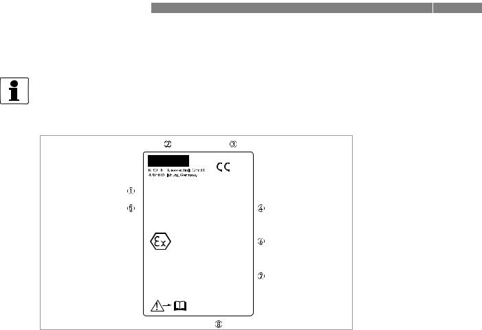
2.3 Nameplate
INFORMATION!
Check on the device nameplates, that the device is supplied according to your order.
|
|
|
0035 |
||
|
|
|
|
|
0102 |
|
|
|
|
|
|
H250/.././M40/..-Ex |
|
MD:201x |
|||
P/A: 011123456.001 |
|
||||
PED/G1/II/H |
PS: xxx bar |
||||
PTmax: xxx bar |
TS: xx °C |
||||
|
|
|
|
|
|
Tag-No.: |
|
|
|
|
|
|
PTB 11 ATEX 2012 X |
||||
|
II2G Ex ia IIC T6 |
|
|
|
|
|
IECEx PTB 11.0069 X |
||||
|
Tamb: -20°C... +60°C |
(T6: +40°C) |
|||
|
|
|
|
|
|
ESK... |
Ui = xxV |
Ii = xxmA |
Pi = xW |
||
|
Ci = xxnF |
Li = xuH |
|
|
|
Kmin1 |
Ui = xxV |
Ii = xxmA |
Pi = xW |
||
Ci = xxnF |
Li = xuH |
|
|
|
|
Kmin2 |
Ui = xxV |
Ii = xxmA |
Pi = xW |
||
Ci = xxnF |
Li = xuH |
|
|
|
|
www.krohne.com
Figure 2-8: Example of a nameplate
1Device type
2Manufacturer
3Notified body
4Rating data: temperature & pressure rating
5PED data
6Ex data
7Electrical connection data
8Internet site
Additional markings on the indicator
•SN - serial number
•SO - sales order / item
•PA - production order
•Vx - product configurator code
•AC - article code
16 |
www.krohne.com |
10/2018 - 4000640705 - MA H250-M40 R05 en |

|
|
DEVICE DESCRIPTION 2 |
|
H250 M40 |
|
|
|
|
2.4 Description code
The description code consists of the following elements *:
Figure 2-9: Description code
1 Device type
H250 - standard version
H250H - horizontal flow direction
H250U - flow direction from top to bottom
2 Materials / versions
RR - stainless steel
C - PTFE or PTFE/ceramics
HC - Hastelloy® Ti - Titanium Mo - Monel
In - Inconel
F - aseptic version (food)
3Heating jacket version
B - with heating jacket
4Type series of indicators
M40 - Indicator M40
M40R - indicator in stainless steel housing
5High-temperature version
HT - version with HT extension
6Electrical signal output
ESK - electrical signal output 4...20 mA (ESK4 / ESK4A)
-optionally available with counter, I/O module and display (ESK4-T)
-Foundation Fieldbus (ESK4-FF)
-Profibus PA (ESK4-PA)
7Limit switches
K1 - one limit switch
K2 - two limit switches
8Explosion protection
Ex - Explosion-protected equipment
9 SIL version
SE - SIL compliant electronic signal output SK - SIL compliant limit switch
* positions which are not needed are omitted (no blank positions)
10/2018 - 4000640705 - MA H250-M40 R05 en |
www.krohne.com |
17 |

2 DEVICE DESCRIPTION |
H250 M40 |
|
2.5 Electronic revision
The electronic revision (sticker on the base module ESK4 / ESK4A) indicates the respective hardware/software status of the electronics. All add-on modules (ESK4-T, ESK4-FF and ESK4PA) have an additional sticker indicating their respective firmware version.
Electronic revision |
Explanations |
|
|
ER 1.1.x |
Basic version (cannot be combined with other indicator versions): |
|
ESK4 / current output 4…20 mA with HART® communication |
|
(ESK4 HART DD 01.01. AMS10x AMS11x |
|
ESK4 HART DD 01.01. PDM6.0 |
|
ESK4 HART DTM 1.0.3 FDT1.2) |
|
|
ER 2.0.x |
Functional add-on to ER 1.1.x: |
|
can be combined with indicator version ESK4 FF / Foundation Fieldbus; |
|
(Firmware version FF module from 1.0.2) |
|
|
ER 2.1.x |
Functional add-on to ER 2.0.x: |
|
can be combined with indicator version ESK4-PA / Profibus PA |
|
(Firmware version PA module from 1.0.0) |
|
can be combined with indicator version ESK4-T / LCD, binary inputs/outputs |
|
(Firmware version T module from 1.1.0) |
|
|
ER 2.2.x |
Functional add-on to ER 2.1.x: |
|
Support of failure signal (low) according to NE 43 |
|
for the ESK4 current output module |
|
|
ER 3.0.x |
Functional add-on: |
|
Update for HART® communication from 5.9 to 7.4 including new DD/DTM |
|
can be combined with ESK4-FF (Firmware version FF module from 1.0.2) |
|
Firmware Version ESK4-PA (... PA module from 1.0.0) |
|
Firmware Version ESK4-T (... T module from 1.2.0) |
Table 2-1: Electronic revision |
|
18 |
www.krohne.com |
10/2018 - 4000640705 - MA H250-M40 R05 en |

|
|
INSTALLATION 3 |
|
H250 M40 |
|
|
|
|
3.1 General installation notes
INFORMATION!
Inspect the packaging carefully for damages or signs of rough handling. Report damage to the carrier and to the local office of the manufacturer.
INFORMATION!
Do a check of the packing list to make sure that you have all the elements given in the order.
INFORMATION!
Look at the device nameplate to ensure that the device is delivered according to your order. Check for the correct supply voltage printed on the nameplate.
3.2Storage
•Store the device in a dry, dust-free location.
•Avoid direct exposure to the sun.
•Store the measuring device in the original packaging.
•The permissible storage temperatures for standard devices are: -40...+80°C / -40...+176°F
10/2018 - 4000640705 - MA H250-M40 R05 en |
www.krohne.com |
19 |

3 INSTALLATION |
H250 M40 |
|
3.3 Installation conditions
CAUTION!
When installing the device in the piping, the following points must be observed:
•The variable area flowmeter must be installed vertically (measuring principle). Flow direction from bottom to top. For installation recommendations please refer also to directive VDI/VDE 3513, sheet 3.
H250Hs are installed horizontally and H250U devices are installed vertically with the flow direction from top to bottom.
•A straight unimpeded inlet run of ≥ 5 DN upstream of the device and a straight outlet run of ≥ 3 DN downstream of the device are recommended.
•Screws, bolts and gaskets are to be provided by the customer and must be selected in accordance with the pressure rating of the connection or the operating pressure.
•The inner diameter of the flange deviates from the standard dimensions. Flange seal standard DIN 2690 or ASME B16.21 can be applied.
•Align the gaskets. Tighten the nuts with the tightening torques of the appropriate pressure rating.
For devices with PTFE liner or ceramic liner and PTFE raised faces, refer to chapter "Tightening torques".
•Control devices are to be positioned downstream of the measuring device.
•Shutoff devices are preferably to be positioned upstream of the measuring device.
•Before connecting, blow or flush out the pipes leading to the device.
•Piping for gas flow need to be dried before the device is installed.
•Use connectors suitable for the particular device version.
•Align the piping centrically with the connection bores on the measuring device so they are free of stresses.
•If necessary, the piping has to be supported to reduce the vibrations transmitted to the measuring device.
•Do not lay signal cables directly next to cables for the power supply.
20 |
www.krohne.com |
10/2018 - 4000640705 - MA H250-M40 R05 en |
|
|
INSTALLATION 3 |
|
H250 M40 |
|
|
|
|
Minimum distance between devices
When several devices are installed next to each other, a minimum distance of > 300 mm / 11.8" between the devices is necessary.
Figure 3-1: Minimum distance between devices
Take special note of the installation position for the H250H with horizontal flow direction:
Figure 3-2: Installation position for H250H
In order to comply with thermal parameters and measuring accuracy, H250H flowmeters for horizontal installation are to be installed in the pipeline so that the display is located on the side of the measuring tube. The maximum product and ambient temperatures indicated as well as the measuring accuracy are based on lateral installation of the indicator.
10/2018 - 4000640705 - MA H250-M40 R05 en |
www.krohne.com |
21 |

3 INSTALLATION |
H250 M40 |
|
3.3.1 Tightening torques
For devices with PTFE liner or ceramic liner and PTFE raised face, tighten the flange threads with the following torques:
Nominal size according to |
|
Stud bolts |
|
|
Max. torque |
|
|||||
|
|
|
|
|
|
|
|
|
|
||
EN 1092-1 |
ASME B16.5 |
EN |
ASME |
EN 1092-1 |
ASME 150 lb |
||||||
|
|
|
|
|
|
|
|
|
|
|
|
DN |
PN |
Inch |
lb |
|
150 lb |
|
300 lb |
Nm |
ft*lbf |
Nm |
ft*lbf |
|
|
|
|
|
|
|
|
|
|
|
|
15 |
40 |
1/2" |
150/300 |
4x M12 |
4x 1/2" |
|
4x 1/2" |
9.8 |
7.1 |
5.2 |
3.8 |
25 |
40 |
1" |
150/300 |
4x M12 |
4x 1/2" |
|
4x 5/8" |
21 |
15 |
10 |
7.2 |
|
|
|
|
|
|
|
|
|
|
|
|
50 |
40 |
2" |
150/300 |
4x M16 |
4x 5/8" |
|
8x 5/8" |
57 |
41 |
41 |
30 |
80 |
16 |
3" |
150/300 |
8x M16 |
4x 5/8" |
|
8x 3/4" |
47 |
34 |
70 |
51 |
|
|
|
|
|
|
|
|
|
|
|
|
100 |
16 |
4" |
150/300 |
8x M16 |
8x 5/8" |
|
8x 3/4" |
67 |
48 |
50 |
36 |
|
|
|
|
|
|
|
|
|
|
|
|
Table 3-1: Tightening torques
3.3.2 Magnetic filters
The use of magnetic filters is recommended when the medium contains particles which can be influenced magnetically. The magnetic filter is to be installed in the flow direction upstream of the flowmeter. Bar magnets are positioned helically in the filter to provide optimal efficiency at low pressure loss. All of the magnets are coated individually with PTFE to protect against corrosion. Material: 1.4404 / 316L
Figure 3-3: Types of magnetic filters
1Type F - fitting part with flange - overall length 100 mm / 4"
2Type FS - fitting part without flange - overall length 50 mm / 2"
22 |
www.krohne.com |
10/2018 - 4000640705 - MA H250-M40 R05 en |

|
|
INSTALLATION 3 |
|
H250 M40 |
|
|
|
|
3.3.3 Heat insulation
CAUTION!
The indicator housing may not be heat-insulated.
The heat insulation 3 may only reach as far as the housing fastening 4.
Figure 3-4: Heat insulation
1Standard indicator M40
2Indicator with HT extension
CAUTION!
The heat insulation 1 may only reach to the rear of the housing 2. The area around the cable entries 3 must be freely accessible.
Figure 3-5: Heat insulation - cross-section
10/2018 - 4000640705 - MA H250-M40 R05 en |
www.krohne.com |
23 |

4 ELECTRICAL CONNECTIONS |
|
|
H250 M40 |
|
|
|
|
|
4.1 Safety instructions
DANGER!
All work on the electrical connections may only be carried out with the power disconnected. Take note of the voltage data on the nameplate!
DANGER!
Observe the national regulations for electrical installations!
DANGER!
For devices used in hazardous areas, additional safety notes apply; please refer to the Ex documentation.
WARNING!
Observe without fail the local occupational health and safety regulations. Any work done on the electrical components of the measuring device may only be carried out by properly trained specialists.
INFORMATION!
Look at the device nameplate to ensure that the device is delivered according to your order. Check for the correct supply voltage printed on the nameplate.
24 |
www.krohne.com |
10/2018 - 4000640705 - MA H250-M40 R05 en |

|
|
ELECTRICAL CONNECTIONS 4 |
|
H250 M40 |
|
|
|
|
4.2 Electrical connection for indicator M40
4.2.1 Connection of the limit switches K1/K2
The M40 indicator can be fitted with a maximum of two limit switches.
The limit switch operates as a proximity switch which is activated inductively by the semicircular metal vane of the pointer. The switching points are set using the contact pointers.
The position of the contact pointers is indicated on the scale.
Figure 4-1: Design of limit switch module
1MIN contact
2MAX contact
3Locking screw
4Peak value
5Connection terminal
The connection terminals have a pluggable design and can be removed to connect the cables. The built-in limit switch types are shown on the nameplate of the indicator.
Contact |
|
MIN |
|
|
MAX |
|
|
|
|
|
|
|
|
Terminal number |
1 |
2 |
3 |
4 |
5 |
6 |
|
|
|
|
|
|
|
Connection 2-wire NAMUR |
- |
+ |
|
- |
+ |
|
|
|
|
|
|
|
|
Connection 3-wire |
+ |
|
- |
+ |
|
- |
|
|
|
|
|
|
|
Connection Reed SPST |
+ |
|
- |
+ |
|
- |
|
|
|
|
|
|
|
Table 4-1: Electrical connection of the limit switches
10/2018 - 4000640705 - MA H250-M40 R05 en |
www.krohne.com |
25 |

4 ELECTRICAL CONNECTIONS |
|
|
H250 M40 |
|
|
|
|
|
Connection diagram for the limit switches
Figure 4-2: Connection terminals for limit switches
1Limit switch 2-wire NAMUR
2Limit switch 3-wire
3Limit switch Reed SPST
4Terminal connection of Min. contact
5Terminal connection of Max. contact
63-wire load
7NAMUR isolated switching amplifier
83-wire power supply
Limit setting
Figure 4-3: Limit setting
1Contact pointer MAX
2Contact pointer MIN
3Locking screw (max. tightening torque is 0.2 Nm)
4Scale support
Setting is carried out directly via contact pointers 1 and 2:
•Pull the upper scale support 2 mm / 0.08" flexibly upwards and pull out the scale from its locking point to the side.
•Loosen the locking screw 3 slightly.
•Slide in the scale up to the locking point.
•Set contact pointers 1 and 2 to the desired switching point.
26 |
www.krohne.com |
10/2018 - 4000640705 - MA H250-M40 R05 en |

|
|
ELECTRICAL CONNECTIONS 4 |
|
H250 M40 |
|
|
|
|
After the setting:
•Pull the upper scale support 2 mm / 0.08" flexibly upwards and pull out the scale again from its locking point to the side.
•Tighten the locking screw 3 with max. 0.2 Nm.
•Slide in the scale up to the locking point.
CAUTION!
If the maximum torque (0.2 Nm) is exceeded, the locking screw can be torn off during tightening!
Definition of switch contact
Figure 4-4: Definition of switch contact
1MIN contact
2MAX contact
3Pointer vane with switching vane
If the pointer vane goes into the slot, an alarm is triggered.
If the pointer vane is outside of the proximity switch, a wire break in a NAMUR contact also triggers the alarm.
The 3-wire limit switch does not have any wire break detection.
Figure 4-5: Definition MIN-MIN - MAX-MAX
1MIN 2 contact or MAX 1 contact
2MIN 1 contact or MAX 2 contact
Contact |
Type |
Current consumption |
|
|
|
MIN 1 |
NAMUR |
≤ 1 mA |
|
|
|
MIN 2 |
NAMUR |
≤ 1 mA |
|
|
|
MAX 1 |
NAMUR |
≥ 3 mA |
|
|
|
MAX 2 |
NAMUR |
≥ 3 mA |
|
|
|
Table 4-2: Current consumption in the position shown:
10/2018 - 4000640705 - MA H250-M40 R05 en |
www.krohne.com |
27 |

4 ELECTRICAL CONNECTIONS |
|
|
H250 M40 |
|
|
|
|
|
4.2.2 Current output ESK4 / ESK4A
The connecting terminals of the ESK4 / ESK4A have a pluggable design and can be removed in order to connect the cables.
Figure 4-6: ESK4 / ESK4A connection
1Current output of ESK4 / ESK4A
2Power supply 14...30 VDC
3Measuring signal 4...20 mA
4External load, HART® communication
Power supply M40 with galvanic isolation
Wiring must be planned with great care when it comes to connecting other devices such as evaluation units or process control. Internal connections in these devices (e.g. GND with PE, mass loops) may lead to non-permitted voltage potentials which could negatively affect the function of the converter itself or that of a device connected to it. In such cases a protected extralow voltage (PELV) is recommended.
Figure 4-7: Power supply M40 with galvanic isolation
1Terminal connection
2Converter supply isolator with galvanic isolation
3Power supply (refer to isolator information)
4Measuring signal 4...20 mA
5External load, HART® communication
28 |
www.krohne.com |
10/2018 - 4000640705 - MA H250-M40 R05 en |
 Loading...