


 OPTIWAVE 7300 C Handbook
Non-contact Radar (FMCW) Level Meter for liquids
for distance, level, volume and mass measurement of liquids
© KROHNE 03/2014 - 4000172405 - HB OPTIWAVE 7300 R07 en
:IMPRINT :::::::::::::::::::::::::::::::::::::::
All rights reserved. It is prohibited to reproduce this documentation, or any part thereof, without the prior written authorisation of KROHNE Messtechnik GmbH.
Subject to change without notice.
Copyright 2014 by
KROHNE Messtechnik GmbH - Ludwig-Krohne-Str. 5 - 47058 Duisburg (Germany)
2 |
www.krohne.com |
03/2014 - 4000172405 - HB OPTIWAVE 7300 R07 en |

|
|
|
CONTENTS |
|
|
||
|
OPTIWAVE 7300 C |
|
|||||
|
|
|
|
|
|
||
1 |
Safety instructions |
7 |
|
||||
|
|
|
|
|
|
|
|
|
|
|
1.1 |
Software history ............................................................................................................... |
7 |
||
|
|
|
1.2 |
Intended use ..................................................................................................................... |
7 |
||
|
|
|
1.3 |
Certification ...................................................................................................................... |
8 |
||
|
|
|
1.4 |
Electromagnetic compatibility ......................................................................................... |
8 |
||
|
|
|
1.5 |
Radio approvals ................................................................................................................ |
9 |
||
|
|
|
1.5.1 European Union (EU)............................................................................................................... |
9 |
|
||
|
|
|
1.5.2 U.S.A. and Canada................................................................................................................. |
10 |
|
||
|
|
|
1.6 |
Safety instructions from the manufacturer ................................................................... |
10 |
||
|
|
|
1.6.1 Copyright and data protection .............................................................................................. |
10 |
|
||
|
|
|
1.6.2 Disclaimer ............................................................................................................................. |
11 |
|
||
|
|
|
1.6.3 Product liability and warranty .............................................................................................. |
12 |
|
||
|
|
|
1.6.4 Information concerning the documentation......................................................................... |
12 |
|
||
|
|
|
1.6.5 Warnings and symbols used................................................................................................. |
13 |
|
||
|
|
|
1.7 |
Safety instructions for the operator............................................................................... |
13 |
|
|
|
|
2 Device description |
14 |
|
|||
|
|
|
|
|
|
||
|
|
|
2.1 |
Scope of delivery............................................................................................................. |
14 |
||
|
|
|
2.2 |
Device description .......................................................................................................... |
16 |
||
|
|
|
2.3 |
Visual Check ................................................................................................................... |
17 |
||
|
|
|
2.4 |
Nameplates .................................................................................................................... |
18 |
||
|
|
|
2.4.1 Non-Ex nameplate ................................................................................................................ |
18 |
|
||
3 |
Installation |
19 |
|
||||
|
|
|
|
|
|
|
|
|
|
|
3.1 |
General notes on installation ......................................................................................... |
19 |
|
|
|
|
|
3.2 |
Storage ........................................................................................................................... |
19 |
||
|
|
|
3.3 |
Transport ........................................................................................................................ |
20 |
||
|
|
|
3.4 |
Pre-installation requirements ....................................................................................... |
20 |
|
|
|
|
|
3.5 |
How to prepare the tank before you install the device.................................................. |
21 |
|
|
|
|
|
3.5.1 Pressure and temperature ranges....................................................................................... |
21 |
|
||
|
|
|
3.5.2 Recommended mounting position........................................................................................ |
22 |
|
||
|
|
|
3.5.3 Theoretical data for hygienic applications ........................................................................... |
23 |
|||
|
|
|
3.6 |
Installation recommendations for liquids...................................................................... |
24 |
|
|
|
|
|
3.6.1 General requirements .......................................................................................................... |
24 |
|
||
|
|
|
3.6.2 Standpipes (stilling wells and bypass chambers) ................................................................ |
25 |
|
||
|
|
|
3.7 |
How to install the device on the tank ............................................................................. |
28 |
|
|
|
|
|
3.7.1 How to install a device with a flange connection ................................................................. |
28 |
|
||
|
|
|
3.7.2 How to install a device with a threaded connection ............................................................. |
30 |
|
||
|
|
|
3.7.3 How to install a device with a hygienic connection .............................................................. |
32 |
|||
|
|
|
3.7.4 How to attach antenna extensions ....................................................................................... |
35 |
|
||
|
|
|
3.7.5 How to turn or remove the signal converter ........................................................................ |
37 |
|
||
|
|
|
3.7.6 How to attach the weather protection to the device............................................................. |
38 |
|||
|
|
|
3.7.7 How to open the weather protection .................................................................................... |
39 |
|
||
03/2014 - 4000172405 - HB OPTIWAVE 7300 R07 en |
www.krohne.com |
3 |

|
CONTENTS |
OPTIWAVE 7300 C |
|
|
|
||
|
|
|
|
4 Electrical connections |
40 |
|
4.1 |
Safety instructions.......................................................................................................... |
40 |
4.2 |
Electrical installation: outputs 1 and 2 .......................................................................... |
40 |
4.2.1 Non-Ex devices ..................................................................................................................... |
41 |
|
4.2.2 Devices for hazardous locations........................................................................................... |
41 |
|
4.3 |
Protection category ........................................................................................................ |
42 |
4.4 |
Networks ........................................................................................................................ |
42 |
4.4.1 General information.............................................................................................................. |
42 |
|
4.4.2 Point-to-point connection..................................................................................................... |
43 |
|
4.4.3 Multi-drop networks ............................................................................................................. |
44 |
|
5 Start-up |
45 |
|
5.1 |
Start-up checklist........................................................................................................... |
45 |
5.2 |
Operating concept .......................................................................................................... |
45 |
5.3 |
Digital display screen ..................................................................................................... |
46 |
5.3.1 Local display screen layout .................................................................................................. |
46 |
|
5.3.2 Keypad buttons ..................................................................................................................... |
46 |
|
5.3.3 Help screens ......................................................................................................................... |
46 |
|
5.3.4 How to start the device ......................................................................................................... |
47 |
|
5.4 |
Remote communication with PACTware™ .................................................................... |
47 |
5.5 |
Remote communication with the AMS™ Device Manager............................................. |
48 |
6 Operation |
49 |
|
6.1 |
User modes .................................................................................................................... |
49 |
6.2 |
Operator mode................................................................................................................ |
49 |
6.3 |
Supervisor mode ............................................................................................................ |
51 |
6.3.1 General notes........................................................................................................................ |
51 |
|
6.3.2 How to get access to the supervisor mode .......................................................................... |
51 |
|
6.3.3 Menu overview ...................................................................................................................... |
52 |
|
6.3.4 Keypad functions................................................................................................................... |
53 |
|
6.3.5 Function description ............................................................................................................. |
57 |
|
6.4 |
Further information on device configuration................................................................. |
68 |
6.4.1 Protection of the device settings .......................................................................................... |
68 |
|
6.4.2 Network configuration .......................................................................................................... |
68 |
|
6.4.3 Linearisation ......................................................................................................................... |
69 |
|
6.4.4 Distance measurement ........................................................................................................ |
69 |
|
6.4.5 Level measurement .............................................................................................................. |
70 |
|
6.4.6 How to configure the device to measure volume or mass................................................... |
72 |
|
6.4.7 How to make a filter to remove radar signal interference .................................................. |
73 |
|
6.4.8 How to measure correctly in tanks with curved or conical bottoms ................................... |
74 |
|
6.5 |
Service mode .................................................................................................................. |
75 |
6.6 |
Errors.............................................................................................................................. |
76 |
6.6.1 General information.............................................................................................................. |
76 |
|
6.6.2 Error handling....................................................................................................................... |
79 |
|
4 |
www.krohne.com |
03/2014 - 4000172405 - HB OPTIWAVE 7300 R07 en |

OPTIWAVE 7300 C |
CONTENTS |
|
7 Service |
82 |
|
7.1 |
Periodic maintenance..................................................................................................... |
82 |
7.2 |
How to clean the top surface of the device .................................................................... |
82 |
7.3 |
How to clean horn antennas under process conditions ................................................ |
83 |
7.4 |
How to replace device components ............................................................................... |
83 |
7.4.1 Service warranty ................................................................................................................... |
83 |
|
7.4.2 Replacement of the display cover......................................................................................... |
84 |
|
7.4.3 Replacement of the complete electronic module ................................................................ |
86 |
|
7.4.4 Replacement of the terminal module................................................................................... |
88 |
|
7.5 |
Spare parts availability................................................................................................... |
90 |
7.6 |
Availability of services .................................................................................................... |
90 |
7.7 |
Returning the device to the manufacturer..................................................................... |
90 |
7.7.1 General information.............................................................................................................. |
90 |
|
7.7.2 Form (for copying) to accompany a returned device............................................................ |
91 |
|
7.8 |
Disposal .......................................................................................................................... |
91 |
8 Technical data |
92 |
|
8.1 |
Measuring principle........................................................................................................ |
92 |
8.2 |
Technical data................................................................................................................. |
93 |
8.3 |
Antenna selection........................................................................................................... |
99 |
8.4 |
Guidelines for maximum operating pressure.............................................................. |
100 |
8.5 |
Dimensions and weights .............................................................................................. |
102 |
9 Description of HART interface |
113 |
|
9.1 |
General description ...................................................................................................... |
113 |
9.2 |
Software history ........................................................................................................... |
113 |
9.3 |
Connection variants...................................................................................................... |
114 |
9.3.1 Point-to-Point connection - analogue / digital mode......................................................... |
114 |
|
9.3.2 Multi-Drop connection (2-wire connection) ....................................................................... |
114 |
|
9.4 |
HART® device variables ............................................................................................... |
115 |
9.5 |
Field Communicator 375/475 (FC 375/475) ................................................................. |
115 |
9.5.1 Installation .......................................................................................................................... |
115 |
|
9.5.2 Operation............................................................................................................................. |
115 |
|
9.6 |
Asset Management Solutions (AMS)............................................................................ |
116 |
9.6.1 Installation .......................................................................................................................... |
116 |
|
9.6.2 Operation............................................................................................................................. |
116 |
|
9.6.3 Parameter for the basic configuration ............................................................................... |
116 |
|
9.7 |
Field Device Tool / Device Type Manager (FDT / DTM)................................................ |
116 |
9.7.1 Installation .......................................................................................................................... |
116 |
|
9.7.2 Operation............................................................................................................................. |
116 |
|
9.8 |
HART® menu tree for Basic-DD .................................................................................. |
117 |
9.8.1 Overview Basic-DD menu tree (positions in menu tree).................................................... |
117 |
|
9.8.2 Basic-DD menu tree (details for settings).......................................................................... |
117 |
|
9.9 |
HART® menu tree for AMS .......................................................................................... |
119 |
9.9.1 Overview AMS menu tree (positions in menu tree)............................................................ |
119 |
|
9.9.2 AMS menu tree (details for settings).................................................................................. |
119 |
|
03/2014 - 4000172405 - HB OPTIWAVE 7300 R07 en |
www.krohne.com |
5 |

|
CONTENTS |
OPTIWAVE 7300 C |
|
|
|
||
|
|
|
|
10 |
Appendix |
122 |
|
|
|
|
|
|
10.1 |
Order code .................................................................................................................. |
122 |
|
10.2 |
List of spare parts ...................................................................................................... |
128 |
|
10.3 |
List of accessories...................................................................................................... |
130 |
|
10.4 |
Glossary ...................................................................................................................... |
132 |
11 |
Notes |
|
135 |
|
|
|
|
6 |
www.krohne.com |
03/2014 - 4000172405 - HB OPTIWAVE 7300 R07 en |

|
|
SAFETY INSTRUCTIONS 1 |
|
OPTIWAVE 7300 C |
|
|
|
|
1.1 Software history
Data about software revisions is shown in the Supervisor menu. Go to Test > Information > Device ID. For more data, refer to Function description on page 57. If it is not possible to refer to the device menu, record the serial number of the device (given on the device nameplate) and speak to the supplier.
Release date |
Back end |
Front end |
DTM revision |
Hardware |
NE 53 level |
(back end) |
|
|
|
|
|
[YYYY-MM-DD] |
|
|
|
|
|
|
|
|
|
|
|
2006-10-31 |
1.0.1.95 |
1.0.0.26 |
1.0.0.32 |
2139580100 |
n/a |
|
|
|
|
|
|
2008-02-01 |
1.01.96 |
1.0.0.27 |
1.0.0.34 |
2139580100 |
3 |
|
|
|
|
|
|
End of back end board ref. 2138270200 production |
|
|
|
||
|
|
|
|
|
|
2010-03-01 |
2.0.2.00 |
1.0.0.28 |
1.0.0.35 |
4000659201 2 |
1 |
|
1.0.2.00 1 |
|
|
|
3 |
|
|
|
|
|
|
2010-05-01 |
2.0.2.01 |
1.0.0.28 |
1.0.0.35 |
4000659201 3 |
3 |
|
1.0.2.01 1 |
|
|
|
n/a |
|
|
|
|
|
|
2012-03-05 |
2.0.2.02 |
1.0.0.28 |
1.0.0.36 |
4000659201 4 |
3 |
|
1.0.2.02 1 |
|
|
|
3 |
2012-03-05 |
2.0.2.03 |
1.0.0.28 |
1.0.0.36 |
4000659201 5 |
3 |
|
1.0.2.03 1 |
|
|
|
3 |
2013-01-22 |
2.0.2.04 |
1.0.0.28 |
1.0.0.37 6 |
4000659201 7 |
3 |
|
1.0.2.04 1 |
|
|
|
3 |
1This back end firmware revision is only used for device upgrades
2It is possible to upgrade the hardware (ref. 2139580100) with back end firmware revision 1.02.00
3It is possible to upgrade the hardware (ref. 2139580100) with back end firmware revision 1.02.01
4It is possible to upgrade the hardware (ref. 2139580100) with back end firmware revision 1.02.02
5It is possible to upgrade the hardware (ref. 2139580100) with back end firmware revision 1.02.03
6If your computer uses the Windows XP operating system, install DTM revision V 1.0.0.36. If your computer uses the Windows 7 operating system, install DTM revision V 1.0.0.37.
7It is possible to upgrade the hardware (ref. 2139580100) with back end firmware revision 1.02.04
1.2 Intended use
This radar level transmitter measures distance, level, mass, volume and reflectivity of liquids, pastes and slurries.
It can be installed on tanks, reactors and open channels.
03/2014 - 4000172405 - HB OPTIWAVE 7300 R07 en |
www.krohne.com |
7 |
1 SAFETY INSTRUCTIONS |
|
|
OPTIWAVE 7300 C |
|
|
|
|
|
1.3 Certification
DANGER!
For devices used in hazardous areas, additional safety notes apply; please refer to the Ex documentation.
In accordance with the commitment to customer service and safety, the device described in this document meets the following safety requirements:
•Electromagnetic Compatibility (EMC) Directive 2004/108/EC in conjunction with EN 61326-1 (2013).
•Radio Equipment and Telecommunications Terminal Equipment (R & TTE) Directive 1999/05/EC in conjunction with ETSI EN 302 372 (2006). For more data, refer to European Union (EU) on page 9.
•Low-Voltage Directive 2006/95/EC in conjunction with EN 61010-1 (2001).
All devices are based on the CE marking and meet the requirements of NAMUR Guideline NE 21 and NE 43.
1.4 Electromagnetic compatibility
The device design agrees with European Standard EN 61326-1.
You can install the device on open-air tanks and tanks that are not made of metal. But refer to Radio approvals on page 9. This agrees with Immunity and Emissions requirements for industrial environments.
INFORMATION!
Device operation agrees with residential-class (class B) immunity and emissions requirements if the antenna is used in a closed tank made of metal.
8 |
www.krohne.com |
03/2014 - 4000172405 - HB OPTIWAVE 7300 R07 en |
|
|
SAFETY INSTRUCTIONS 1 |
|
OPTIWAVE 7300 C |
|
|
|
|
1.5 Radio approvals
1.5.1 European Union (EU)
LEGAL NOTICE!
This level transmitter is intended for installation in closed metallic tanks. It meets the requirements of the R & TTE (Radio Equipment and Telecommunications Terminal Equipment) Directive 1999/05/EC for use in the member countries of the EU.
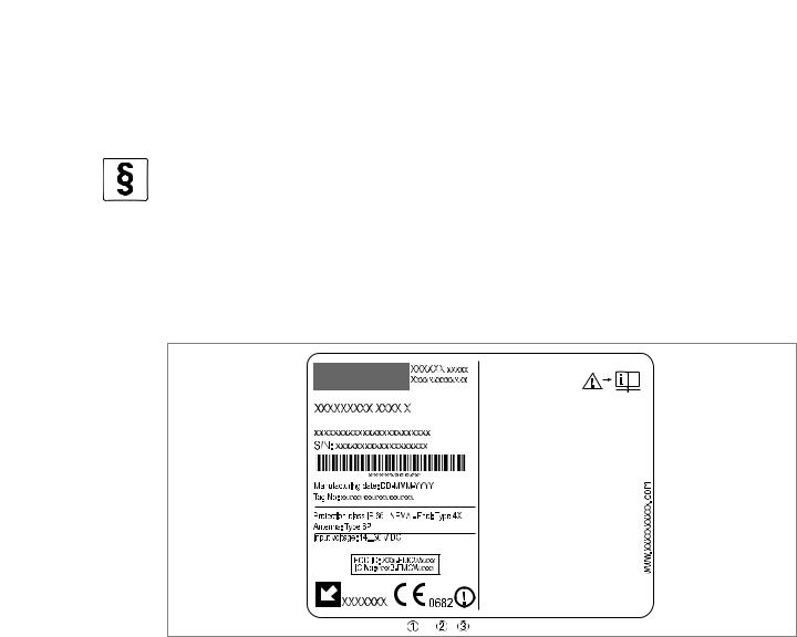
The device operates using a frequency band (24...26 GHz) that is not harmonized within the EU. According to article 6.4 of the R&TTE Directive, the product is marked by the CE sign + notified body number (0682) + Class II identifier (= alert sign).
Refer to EN 302372 for installation conditions.
Figure 1-1: Radio approval information on the nameplate
1CE sign
2Notified body number (0682 = CETECOM)
3Class II identifier
According to ETSI EN 302 372 (2006-04), the radiated power outside a metallic tank is less than -30 dBm.
The radio approval report is given on the DVD-ROM supplied with the device.
03/2014 - 4000172405 - HB OPTIWAVE 7300 R07 en |
www.krohne.com |
9 |

1 SAFETY INSTRUCTIONS |
|
|
OPTIWAVE 7300 C |
|
|
|
|
|
1.5.2 U.S.A. and Canada
LEGAL NOTICE!
This device complies with Part 15 of the FCC Rules and with RSS-210 of Industry Canada.
Operation is subject to the following two conditions:
1.This device may not cause harmful interference, and
2.This device must accept any interference received, including interference which may cause undesired operation.
Changes or modifications made to this equipment not expressly approved by the manufacturer may void the FCC and IC authorizations to operate this equipment.
This legal information is shown on a label on the rear side of the device.
The radio approval report is given on the DVD-ROM supplied with the device.
1.6 Safety instructions from the manufacturer
1.6.1 Copyright and data protection
The contents of this document have been created with great care. Nevertheless, we provide no guarantee that the contents are correct, complete or up-to-date.
The contents and works in this document are subject to copyright. Contributions from third parties are identified as such. Reproduction, processing, dissemination and any type of use beyond what is permitted under copyright requires written authorisation from the respective author and/or the manufacturer.
The manufacturer tries always to observe the copyrights of others, and to draw on works created in-house or works in the public domain.
The collection of personal data (such as names, street addresses or e-mail addresses) in the manufacturer's documents is always on a voluntary basis whenever possible. Whenever feasible, it is always possible to make use of the offerings and services without providing any personal data.
We draw your attention to the fact that data transmission over the Internet (e.g. when communicating by e-mail) may involve gaps in security. It is not possible to protect such data completely against access by third parties.
We hereby expressly prohibit the use of the contact data published as part of our duty to publish an imprint for the purpose of sending us any advertising or informational materials that we have not expressly requested.
10 |
www.krohne.com |
03/2014 - 4000172405 - HB OPTIWAVE 7300 R07 en |
|
|
SAFETY INSTRUCTIONS 1 |
|
OPTIWAVE 7300 C |
|
|
|
|
1.6.2 Disclaimer
The manufacturer will not be liable for any damage of any kind by using its product, including, but not limited to direct, indirect or incidental and consequential damages.
This disclaimer does not apply in case the manufacturer has acted on purpose or with gross negligence. In the event any applicable law does not allow such limitations on implied warranties or the exclusion of limitation of certain damages, you may, if such law applies to you, not be subject to some or all of the above disclaimer, exclusions or limitations.
Any product purchased from the manufacturer is warranted in accordance with the relevant product documentation and our Terms and Conditions of Sale.
The manufacturer reserves the right to alter the content of its documents, including this disclaimer in any way, at any time, for any reason, without prior notification, and will not be liable in any way for possible consequences of such changes.
03/2014 - 4000172405 - HB OPTIWAVE 7300 R07 en |
www.krohne.com |
11 |

1 SAFETY INSTRUCTIONS |
|
|
OPTIWAVE 7300 C |
|
|
|
|
|
1.6.3 Product liability and warranty
The operator shall bear responsibility for the suitability of the device for the specific purpose. The manufacturer accepts no liability for the consequences of misuse by the operator. Improper installation and operation of the devices (systems) will cause the warranty to be void. The respective "Standard Terms and Conditions" which form the basis for the sales contract shall also apply.
1.6.4 Information concerning the documentation
To prevent any injury to the user or damage to the device it is essential that you read the information in this document and observe applicable national standards, safety requirements and accident prevention regulations.
If this document is not in your native language and if you have any problems understanding the text, we advise you to contact your local office for assistance. The manufacturer can not accept responsibility for any damage or injury caused by misunderstanding of the information in this document.
This document is provided to help you establish operating conditions, which will permit safe and efficient use of this device. Special considerations and precautions are also described in the document, which appear in the form of underneath icons.
12 |
www.krohne.com |
03/2014 - 4000172405 - HB OPTIWAVE 7300 R07 en |

|
|
SAFETY INSTRUCTIONS 1 |
|
OPTIWAVE 7300 C |
|
|
|
|
1.6.5 Warnings and symbols used
Safety warnings are indicated by the following symbols.
DANGER!
This warning refers to the immediate danger when working with electricity.
DANGER!
This warning refers to the immediate danger of burns caused by heat or hot surfaces.
DANGER!
This warning refers to the immediate danger when using this device in a hazardous atmosphere.
DANGER!
These warnings must be observed without fail. Even partial disregard of this warning can lead to serious health problems and even death. There is also the risk of seriously damaging the device or parts of the operator's plant.
WARNING!
Disregarding this safety warning, even if only in part, poses the risk of serious health problems. There is also the risk of damaging the device or parts of the operator's plant.
CAUTION!
Disregarding these instructions can result in damage to the device or to parts of the operator's plant.
INFORMATION!
These instructions contain important information for the handling of the device.
LEGAL NOTICE!
This note contains information on statutory directives and standards.
• HANDLING
This symbol designates all instructions for actions to be carried out by the operator in the specified sequence.
iRESULT
This symbol refers to all important consequences of the previous actions.
1.7Safety instructions for the operator
WARNING!
In general, devices from the manufacturer may only be installed, commissioned, operated and maintained by properly trained and authorized personnel.
This document is provided to help you establish operating conditions, which will permit safe and efficient use of this device.
03/2014 - 4000172405 - HB OPTIWAVE 7300 R07 en |
www.krohne.com |
13 |

2 DEVICE DESCRIPTION |
OPTIWAVE 7300 C |
|
2.1 Scope of delivery
INFORMATION!
Do a check of the packing list to make sure that you have all the elements given in the order.
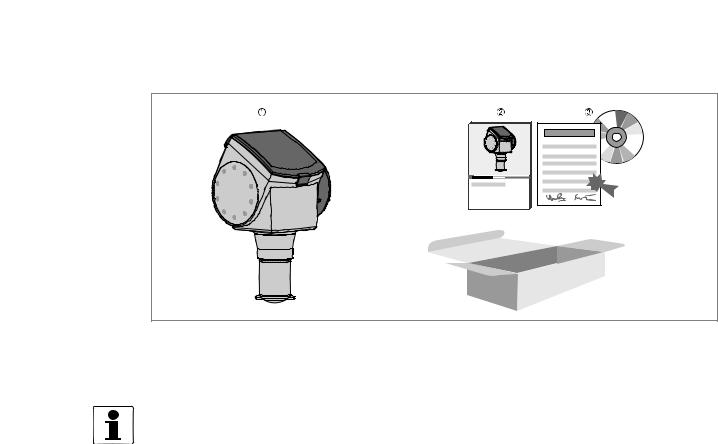
Scope of delivery – horn antenna
Figure 2-1: Scope of delivery – horn antenna
1Signal converter and antenna in compact version
2Antenna extensions (option)
3Quick Start
4DVD-ROM (including Handbook, Quick Start, Technical Datasheet and related software)
Scope of delivery – Drop antenna
Figure 2-2: Scope of delivery – Drop antenna
1Signal converter and antenna in compact version
2Antenna extensions (option) and o-ring for each antenna extension
3Quick Start
4DVD-ROM (including Handbook, Quick Start, Technical Datasheet, and related software)
14 |
www.krohne.com |
03/2014 - 4000172405 - HB OPTIWAVE 7300 R07 en |
|
|
DEVICE DESCRIPTION 2 |
|
OPTIWAVE 7300 C |
|
|
|
|
Scope of delivery – hygienic antenna
Figure 2-3: Scope of delivery – hygienic antenna
1Signal converter and antenna in compact version
2Quick Start
3DVD-ROM (including Handbook, Quick Start, Technical Datasheet, and related software)
INFORMATION!
No special tools or training required!
03/2014 - 4000172405 - HB OPTIWAVE 7300 R07 en |
www.krohne.com |
15 |

2 DEVICE DESCRIPTION |
OPTIWAVE 7300 C |
|
2.2 Device description
This device is a 24 GHz FMCW-radar level transmitter. It is a non-contact technology and is 2- wire loop-powered. It is designed to measure the distance, level, mass, volume and reflectivity of liquids, pastes and slurries.
Radar level transmitters use an antenna to guide a signal to the surface of the measured product. The device has many antennas available. Thus, it can measure most products even in difficult conditions. Also refer to Technical data on page 92.
The device has a set-up wizard, fully-potted electronic circuit boards and online help functions.
You usually will not need this Handbook to install, set up and operate the device.
If it is ordered with the applicable options, it can be certified for use in hazardous areas.
These output options are available:
•1 output: 4...20 mA (HART)
•2 outputs: 4...20 mA (HART) + 4...20 mA
These accessories are available:
•Stainless steel weather protection.
•RS232 / HART® converter (VIATOR).
•USB / HART® converter.
INFORMATION!
For more data on accessories, refer to List of accessories on page 130.
16 |
www.krohne.com |
03/2014 - 4000172405 - HB OPTIWAVE 7300 R07 en |

|
|
DEVICE DESCRIPTION 2 |
|
OPTIWAVE 7300 C |
|
|
|
|
2.3 Visual Check
WARNING!
If the display screen glass is broken, do not touch.
INFORMATION!
Inspect the packaging carefully for damages or signs of rough handling. Report damage to the carrier and to the local office of the manufacturer.
Figure 2-4: Visual check
1Device nameplate (for more data, refer to Non-Ex nameplate on page 18)
2Process connection data (size and pressure rating, material reference and heat number)
3Gasket material data - refer to the illustration that follows
Figure 2-5: Symbols for the supplied gasket material (on the side of the process connection)
1EPDM
2Kalrez® 6375
If the device is supplied with an FKM/FPM gasket, there is no symbol on the side of the process connection.
INFORMATION!
Look at the device nameplate to ensure that the device is delivered according to your order. Check for the correct supply voltage printed on the nameplate.
INFORMATION!
Compare the material references on the side of the process connection with the order.
03/2014 - 4000172405 - HB OPTIWAVE 7300 R07 en |
www.krohne.com |
17 |
2 DEVICE DESCRIPTION |
OPTIWAVE 7300 C |
|
2.4 Nameplates
INFORMATION!
Look at the device nameplate to ensure that the device is delivered according to your order. Check for the correct supply voltage printed on the nameplate.
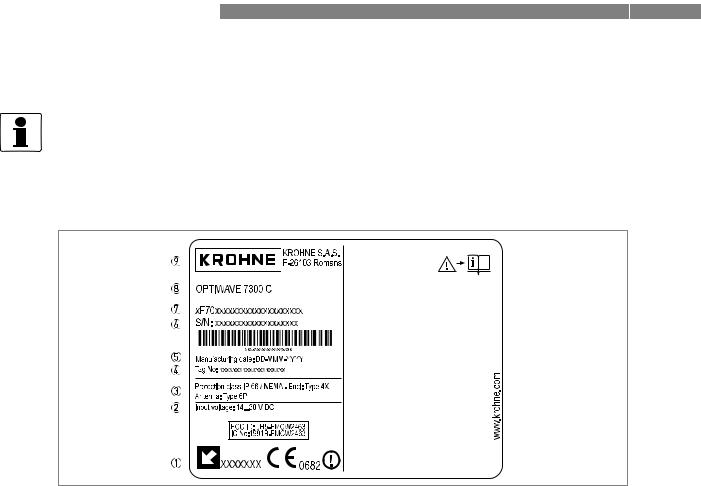
2.4.1 Non-Ex nameplate
Figure 2-6: Non-Ex nameplate
1Indicator arrow to cable entry / cable entry size. Notified body for radio approval.
2Nominal voltage for operation. For further information, refer to Non-Ex devices on page 41.
3Degree of ingress protection (according to EN 60529 / IEC 60529)
4Customer tag number
5Date of manufacture
6Order number
7Type code (defined in order)
8Model name and number
9Company name and address
18 |
www.krohne.com |
03/2014 - 4000172405 - HB OPTIWAVE 7300 R07 en |
|
|
INSTALLATION 3 |
|
OPTIWAVE 7300 C |
|
|
|
|
3.1 General notes on installation
INFORMATION!
Inspect the packaging carefully for damages or signs of rough handling. Report damage to the carrier and to the local office of the manufacturer.
INFORMATION!
Do a check of the packing list to make sure that you have all the elements given in the order.
INFORMATION!
Look at the device nameplate to ensure that the device is delivered according to your order. Check for the correct supply voltage printed on the nameplate.
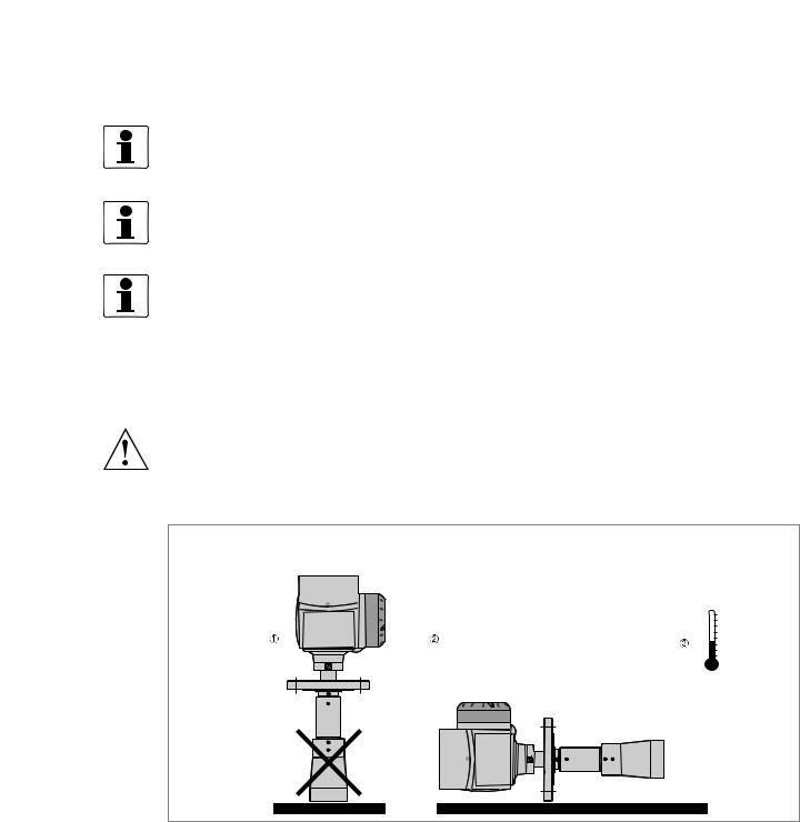
3.2 Storage
WARNING!
Do not keep the device in a vertical position. This will damage the antenna and the device will not measure correctly.
Figure 3-1: Storage conditions
1When you put the device into storage, do not keep it in a vertical position
2Put the device on its side. We recommend that you use the packaging in which it was delivered.
3Storage temperature range: -40...+85°C / -40...+185°F
•Store the device in a dry and dust-free location.
•Keep the converter out of the sunlight.
•Store the device in its original packing.
03/2014 - 4000172405 - HB OPTIWAVE 7300 R07 en |
www.krohne.com |
19 |
3 INSTALLATION |
OPTIWAVE 7300 C |
|
3.3 Transport
Figure 3-2: How to lift the device
1 Remove the converter before you lift the device with a hoist.
WARNING!
Lift the device carefully to prevent damage to the antenna.
3.4 Pre-installation requirements
INFORMATION!
Obey the precautions that follow to make sure that the device is correctly installed.
•Make sure that there is sufficient space on all sides.
•Protect the signal converter from direct sunlight. If necessary, install the weather protection accessory.
•Do not subject the signal converter to heavy vibrations. The devices are tested for vibration and agree with EN 50178 and IEC 60068-2-6.
20 |
www.krohne.com |
03/2014 - 4000172405 - HB OPTIWAVE 7300 R07 en |
|
|
INSTALLATION 3 |
|
OPTIWAVE 7300 C |
|
|
|
|
3.5 How to prepare the tank before you install the device
CAUTION!
To avoid measuring errors and device malfunction, obey these precautions.
3.5.1 Pressure and temperature ranges
Figure 3-3: Pressure and temperature ranges
1Flange temperature
FKM/FPM gasket: -40...+200°C / -40...+390°F; Kalrez® 6375 gasket: -20...+200°C / -4...+390°F; EPDM gasket: -50...+150°C / -58...+300°F
Depends on the antenna type. Refer to the table that follows. Ex devices: see supplementary operating instructions
2Ambient temperature for operation of the display -20...+60°C / -4...+140°F
If the ambient temperature is not between these limits, the display screen switches off automatically
3Ambient temperature
Non-Ex devices: -40...+80°C / -40...+175°F
Ex devices: see supplementary operating instructions
4Process pressure
Depends on the antenna type. Refer to the table that follows.
WARNING!
The process connection temperature range must agree with the temperature limits of the gasket material. The operating pressure range is subject to the process connection used and the flange temperature.
Antenna type |
Maximum process connection |
Maximum operating pressure |
||
|
temperature |
|
|
|
|
|
|
|
|
|
[°C] |
[°F] |
barg |
psig |
|
|
|
|
|
PP Drop |
+100 |
+210 |
16 |
232 |
|
|
|
|
|
PTFE Drop |
+150 |
+300 |
40 |
580 |
|
|
|
|
|
Hygienic |
+150 |
+300 |
10 |
145 |
|
|
|
|
|
Horn / Sheet metal horn |
+150 (+200) 1 |
+300 (+390) 1 |
40 (100) 2 |
580 (1450) 2 |
|
|
|
|
|
1Standard max. process connection temperature: +150°C / +300°F. Optional max. process temperature: +200°C / +390°F.
2Standard max. operating pressure: 40 barg / 580 psig. Optional max. operating pressure: 100 barg / 1450 psig.
03/2014 - 4000172405 - HB OPTIWAVE 7300 R07 en |
www.krohne.com |
21 |
3 INSTALLATION |
OPTIWAVE 7300 C |
|
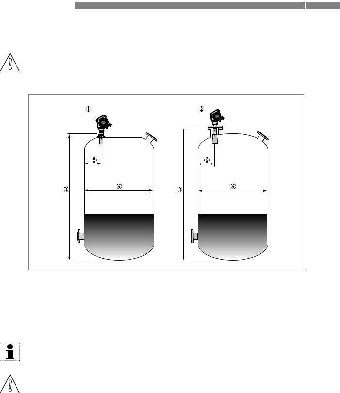
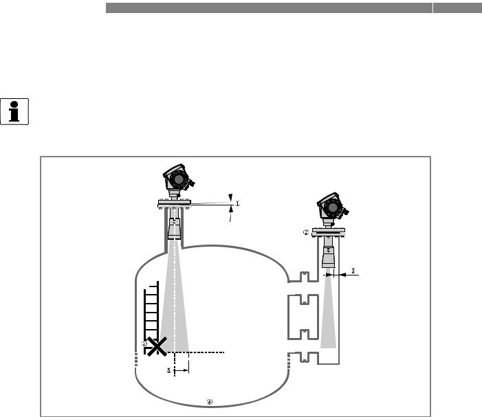
3.5.2 Recommended mounting position
CAUTION!
Follow these recommendations to make sure that the device measures correctly.
Figure 3-4: Recommended nozzle position for liquids, pastes and slurries
1Nozzles for DN40 or DN50 Horn antennas, or DN50 Hygienic antenna
2Nozzles for DN80, DN100, DN150 or DN200 Horn antennas, or DN80 or DN150 Drop antenna
3Tank height
4Tank diameter
5Minimum distance of nozzle from the tank wall : 1/7 × tank height Maximum distance of nozzle from the tank wall : 1/3 × tank diameter
6Minimum distance of nozzle from the tank wall : 1/10 × tank height Maximum distance of nozzle from the tank wall : 1/3 × tank diameter
INFORMATION!
If possible, do not install a nozzle on the tank centerline.
CAUTION!
Do not put the device near to the product inlet. If the product that enters the tank touches the antenna, the device will measure incorrectly. If the product fills the tank directly below the antenna, the device will also measure incorrectly.
22 |
www.krohne.com |
03/2014 - 4000172405 - HB OPTIWAVE 7300 R07 en |
|
|
|
|
|
|
|
|
|
INSTALLATION 3 |
|
OPTIWAVE 7300 C |
||||||||
|
|
|
|
|
|
|
|
|
|
|
|
|
|
|
|
|
|
|
|
|
|
|
|
|
|
|
|
|
|
|
|
|
|
|
|
|
|
|
|
|
|
|
|
|
|
|
|
|
|
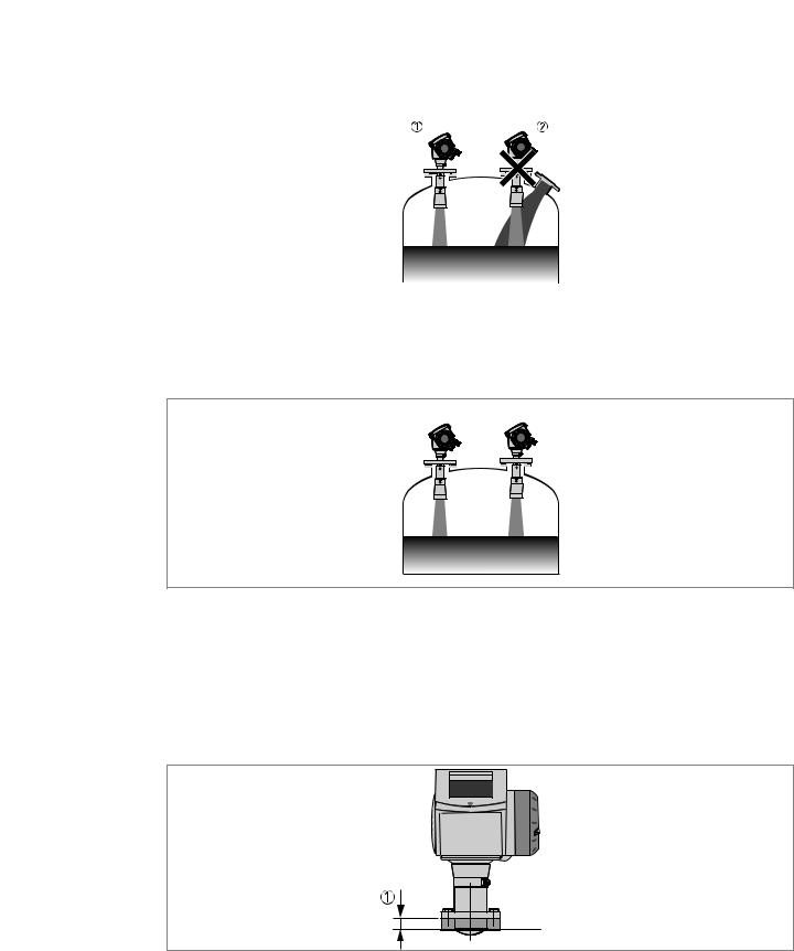
Figure 3-5: Product inlets
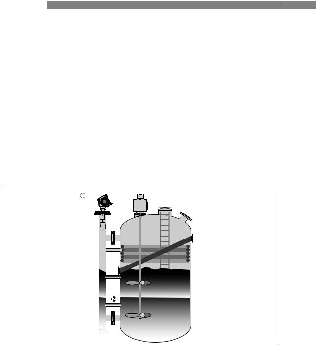
1The device is in the correct position.
2The device is too near to the product inlet.
Figure 3-6: More than 1 FMCW radar level meter can be operated in a tank
More than 1 FMCW radar level meter can be operated in a tank.
3.5.3 Theoretical data for hygienic applications
To make the cleaning of the antenna easier, attach the device to a short socket.
Figure 3-7: Requirements for hygienic applications
1 Maximum height of process connection: 50 mm / 2¨
03/2014 - 4000172405 - HB OPTIWAVE 7300 R07 en |
www.krohne.com |
23 |
3 INSTALLATION |
OPTIWAVE 7300 C |
|
3.6 Installation recommendations for liquids
3.6.1 General requirements
INFORMATION!
We recommend that you configure the device when the tank is empty.
Figure 3-8: General Installation recommendations
1Do not tilt the device more than 2°
2We recommend that you do an empty spectrum recording if there are too many obstacles in the radar beam (for more data, refer to How to make a filter to remove radar signal interference on page 73), or install a bypass chamber or stilling well.
32.5 mm / 0.1¨ max. for high-dielectric constant liquids
4Curved and conical tank bottoms. For fine adjustment of the device, refer to How to measure correctly in tanks with curved or conical bottoms on page 74.
5Beam radius (DN40 horn antenna): increments of 180 mm/m or 2.15¨/ft (10°)
Beam radius (DN50 horn antenna or DN50 Hygienic antenna): increments of 130 mm/m or 1.55¨/ft (7.5°) Beam radius (DN80 horn antenna): increments of 90 mm/m or 1.1¨/ft (5°)
Beam radius (DN100 horn antenna, DN150 horn antenna, DN200 horn antenna or DN80 Drop antenna): increments of 70 mm/m or 0.83¨/ft (4°)
Beam radius (DN150 Drop antenna): increments of 35 mm/m or 0.42¨/ft (2°)
24 |
www.krohne.com |
03/2014 - 4000172405 - HB OPTIWAVE 7300 R07 en |
|
|
INSTALLATION 3 |
|
OPTIWAVE 7300 C |
|
|
|
|
3.6.2 Standpipes (stilling wells and bypass chambers)
Use a standpipe if:
•There is highly conductive foam in the tank.
•The liquid is very turbulent or agitated.
•There are too many other objects in the tank.
•The device is measuring a liquid (petro-chemicals) in a tank with a floating roof.
•The device is installed in a horizontal cylindrical tank (refer to the end of this section)
Figure 3-9: Installation recommendations for standpipes (stilling wells and bypass chambers)
1A stilling well solution
2A bypass chamber solution
3Air circulation hole
4Level of the liquid
CAUTION!
Installation requirements
•The standpipe must be electrically conductive.
•The inside diameter of the standpipe must not be more than 5 mm / 0.2¨ over the diameter of the antenna (for a high-dielectric constant liquid).
•The standpipe must be straight. There must be no sudden changes in internal diameter greater than 1 mm / 0.04¨.
•The standpipe must be vertical.
•Recommended surface roughness: <±0.1 mm / 0.004¨.
•Stilling well only: The bottom of the stilling well must be open.
•Make sure that there are no deposits at the bottom of the standpipe.
•Make sure that there is liquid in the standpipe.
03/2014 - 4000172405 - HB OPTIWAVE 7300 R07 en |
www.krohne.com |
25 |
3 INSTALLATION |
OPTIWAVE 7300 C |
|
Stilling wells - general notes
Installation in tanks containing one liquid and foam
•Drill an air circulation hole (max. Ø10 mm / 0.4¨) in the stilling well above the maximum level.
•Remove the burr from the hole.
Installation in tanks containing one liquid or more without foam
•Drill an air circulation hole (max. Ø10 mm / 0.4¨) in the stilling well above the maximum level.
•Drill 1 or more liquid circulation holes in the stilling well (if there is more than 1 liquid in the tank).
i These holes help the liquid to move freely between the stilling well and the tank.
• Remove the burr from the hole.
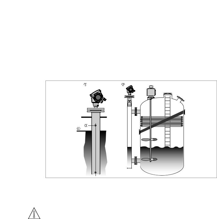
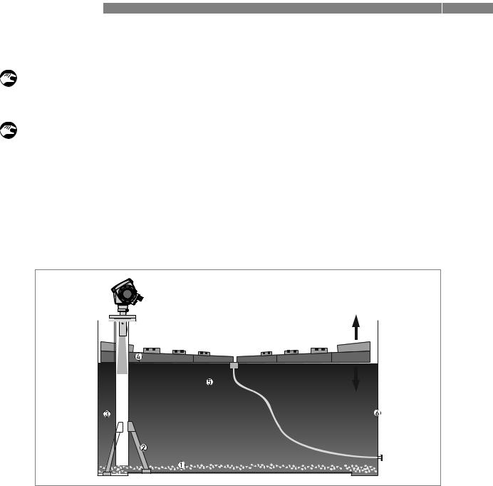
Stilling wells: floating roofs
If the device must be installed on a tank with a floating roof, install it in a stilling well.
Figure 3-10: Floating roofs
1Sediment
2Support fixtures
3Stilling well
4Floating roof
5Product
6Tank
26 |
www.krohne.com |
03/2014 - 4000172405 - HB OPTIWAVE 7300 R07 en |
|
|
INSTALLATION 3 |
|
OPTIWAVE 7300 C |
|
|
|
|
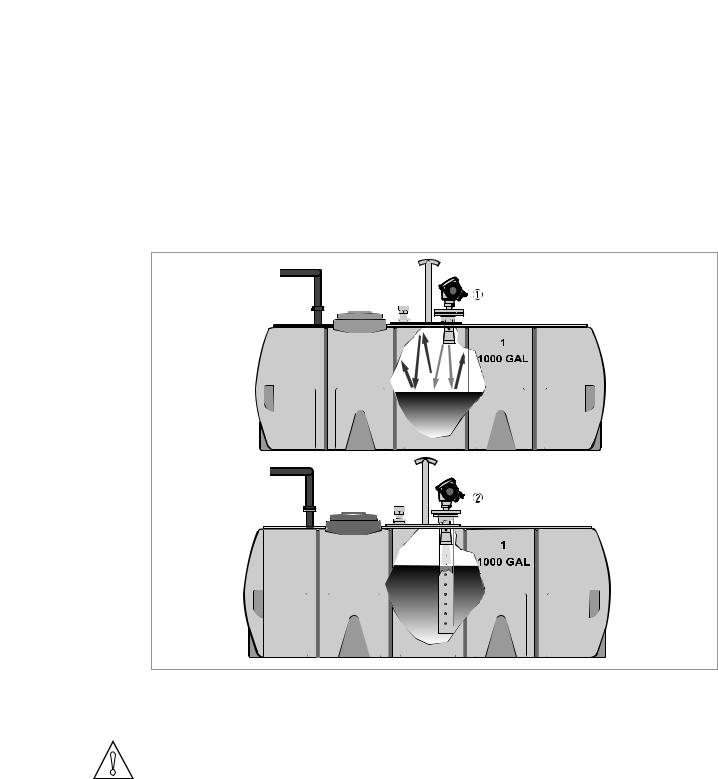
Stilling wells: horizontal cylindrical tanks
We recommend that you install the device in a stilling well if the device:
•is for a horizontal cylindrical tank,
•is in a metallic tank,
•measures a product with a high dielectric constant and
•is on the centerline of the tank.
Figure 3-11: Horizontal cylindrical tanks
1The device is installed without a stilling well. There are multiple reflections. Refer to the CAUTION! that follows.
2The device is installed in a stilling well and measures correctly.
CAUTION!
If the device is installed in horizontal cylindrical tank that contains a high dielectric constant liquid without a stilling well, do not put it on the tank centerline. This will cause multiple reflections and the device will not measure accurately. Use the Multiple Reflections function in
Supervisor > Advanced Setup > Installation Setup to keep the effects of multiple reflections to a minimum. For more data, refer to Function description on page 57 (C. Advanced Setup).
03/2014 - 4000172405 - HB OPTIWAVE 7300 R07 en |
www.krohne.com |
27 |
3 INSTALLATION |
OPTIWAVE 7300 C |
|
Bypass chambers
Installation next to tanks containing one liquid and foam
•The top process connection of the bypass chamber must be above the maximum level of liquid.
•The bottom process connection of the bypass chamber must be below the lowest measured level of liquid.
Installation next to tanks containing more than one liquid
•The top process connection of the bypass chamber must be above the maximum level of liquid.
•The bottom process connection of the bypass chamber must be below the lowest measured level of liquid.
•Additional process connections are necessary for the liquids to circulate freely along the length of the bypass chamber.
Figure 3-12: Installation recommendations for bypass chambers that contain more than one liquid
1Bypass chamber
2Additional process connection
3.7How to install the device on the tank
3.7.1 How to install a device with a flange connection
Equipment needed:
•Device
•Gasket (not supplied)
•Nuts and bolts (not supplied)
•Wrench (not supplied)
28 |
www.krohne.com |
03/2014 - 4000172405 - HB OPTIWAVE 7300 R07 en |
|
|
INSTALLATION 3 |
|
OPTIWAVE 7300 C |
|
|
|
|
Requirements for flange connections
Figure 3-13: Flange connection
If the antenna is smaller than the process connection:
•Make sure the flange on the nozzle is level.
•Make sure that you use the applicable gasket for the flange dimensions and the process.
•Align the gasket correctly on the flange facing of the nozzle.
•Lower the antenna carefully into the tank.
•Tighten the flange bolts.
i Refer to local rules and regulations for the correct torque to apply to the bolts.
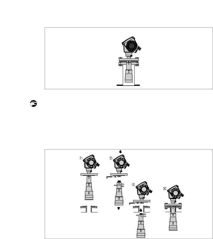
Figure 3-14: How to attach the device if the antenna is larger than the process connection
Equipment needed:
• 3 mm Allen wrench (not supplied)
03/2014 - 4000172405 - HB OPTIWAVE 7300 R07 en |
www.krohne.com |
29 |

3 INSTALLATION |
OPTIWAVE 7300 C |
|
WARNING!
If you attach the antenna in a closed space, make sure that there is a good airflow in the area. Make sure that a person not in the tank can always hear you.
If the antenna is larger than the process connection:
•Make sure the flange on the nozzle is level.
•Remove the antenna locking screw from the part below the flange.
•Remove the antenna from the part below the flange.
•Align the gasket correctly on the flange facing of the nozzle.
•Put the device carefully on the tank flange. Do not attach the device flange to the tank yet.
•Attach the antenna to the device inside the tank. Go to the top of the tank.
•Lift the device a small distance. Attach the antenna locking screw to the part below the flange. Tighten the antenna locking screw.
•Put the device carefully on the tank flange. Tighten the flange bolts.
3.7.2How to install a device with a threaded connection
Equipment needed:
•Device
•Gasket for G 1½ connection (not supplied)
•50 mm / 2¨ wrench (not supplied)
Requirements for threaded connections
Figure 3-15: Threaded connection
If the antenna is smaller than the process connection:
•Make sure the tank connection is level.
•Make sure that you use the applicable gasket for the connection dimensions and the process.
•Align the gasket correctly.
•Lower the antenna carefully into the tank.
•Turn the threaded connection on the housing to attach the device to the process connection.
•Tighten the connection.
i Refer to local rules and regulations for the correct torque to apply to the connection.
30 |
www.krohne.com |
03/2014 - 4000172405 - HB OPTIWAVE 7300 R07 en |
 Loading...