


 BATCHFLUX 5500 C Handbook
Electromagnetic flowmeter for volumetric filling machines
© KROHNE 05/2014 - 4000827703 - HB BATCHFLUX 5500 R03 en
: IMPRINT :::::::::::::::::::::::::::::::::::::::
All rights reserved. It is prohibited to reproduce this documentation, or any part thereof, without the prior written authorisation of KROHNE Messtechnik GmbH.
Subject to change without notice.
Copyright 2014 by
KROHNE Messtechnik GmbH - Ludwig-Krohne-Str. 5 - 47058 Duisburg (Germany)
2 |
www.krohne.com |
05/2014 - 4000827703 - HB BATCHFLUX 5500 R03 en |

|
|
|
CONTENTS |
|
|
||
|
BATCHFLUX 5500 C |
|
|||||
|
|
|
|
|
|
||
1 |
Safety instructions |
5 |
|
||||
|
|
|
|
|
|
|
|
|
|
|
1.1 |
Intended use ..................................................................................................................... |
5 |
|
|
|
|
|
1.2 |
Safety instructions from the manufacturer ..................................................................... |
5 |
|
|
|
|
|
1.2.1 Disclaimer ............................................................................................................................... |
5 |
|
||
|
|
|
1.2.2 Information concerning the documentation........................................................................... |
5 |
|
||
|
|
|
1.2.3 Warnings and symbols used................................................................................................... |
6 |
|
||
|
|
|
1.3 |
Safety instructions for the operator................................................................................. |
6 |
|
|
|
|
2 Device description |
7 |
|
|||
|
|
|
|
|
|
||
|
|
|
2.1 |
Scope of delivery............................................................................................................... |
7 |
||
|
|
|
2.2 |
Device description ............................................................................................................ |
8 |
||
|
|
|
2.3 |
Nameplate ........................................................................................................................ |
9 |
|
|
3 |
Installation |
10 |
|
||||
|
|
|
|
|
|
|
|
|
|
|
3.1 |
General notes on installation ......................................................................................... |
10 |
|
|
|
|
|
3.2 |
Storage ........................................................................................................................... |
10 |
||
|
|
|
3.3 |
Pre-installation requirements ....................................................................................... |
10 |
||
|
|
|
3.4 |
General requirements .................................................................................................... |
11 |
|
|
|
|
|
3.5 |
Installation conditions .................................................................................................... |
12 |
||
|
|
|
3.5.1 Inlet and outlet ...................................................................................................................... |
12 |
|
||
|
|
|
3.5.2 Control valve ......................................................................................................................... |
12 |
|
||
|
|
|
3.5.3 Pump ..................................................................................................................................... |
12 |
|
||
|
|
|
3.5.4 Open feed or discharge......................................................................................................... |
13 |
|
||
|
|
|
3.5.5 Mounting position.................................................................................................................. |
13 |
|
||
|
|
|
3.5.6 Mounting ............................................................................................................................... |
14 |
|
||
|
|
|
3.5.7 Installation location .............................................................................................................. |
14 |
|
||
|
|
|
3.5.8 Flange deviation .................................................................................................................... |
14 |
|
||
|
|
|
3.5.9 Temperatures ....................................................................................................................... |
15 |
|
||
|
|
|
3.5.10 Hot filling............................................................................................................................. |
15 |
|
||
|
|
4 Electrical connections |
16 |
|
|||
|
|
|
|
|
|
||
|
|
|
4.1 |
Safety instructions.......................................................................................................... |
16 |
||
|
|
|
4.2 |
Grounding ....................................................................................................................... |
16 |
||
|
|
|
4.3 |
Electrical connection...................................................................................................... |
17 |
||
|
|
|
4.3.1 Cable connector M12 - 5 pin................................................................................................. |
17 |
|
||
|
|
|
4.3.2 Cable connector M12 - 8 pin (with status output) ................................................................ |
18 |
|
||
|
|
5 Service |
19 |
|
|||
|
|
|
|
|
|
||
|
|
|
5.1 |
Spare parts availability................................................................................................... |
19 |
||
|
|
|
5.2 |
Availability of services .................................................................................................... |
19 |
||
|
|
|
5.3 |
Returning the device to the manufacturer..................................................................... |
19 |
|
|
|
|
|
5.3.1 General information.............................................................................................................. |
19 |
|
||
|
|
|
5.3.2 Form (for copying) to accompany a returned device............................................................ |
20 |
|
||
|
|
|
5.4 |
Disposal .......................................................................................................................... |
20 |
||
05/2014 - 4000827703 - HB BATCHFLUX 5500 R03 en |
www.krohne.com |
3 |

|
CONTENTS |
BATCHFLUX 5500 C |
|
|
|
||
|
|
|
|
6 |
Technical data |
21 |
|
|
|
|
|
|
6.1 |
Measuring principle........................................................................................................ |
21 |
|
6.2 |
Technical data................................................................................................................. |
22 |
|
6.3 |
Dimensions and weights ................................................................................................ |
26 |
|
6.4 |
Counter Flanges ............................................................................................................. |
29 |
7 |
Notes |
|
31 |
|
|
|
|
4 |
www.krohne.com |
05/2014 - 4000827703 - HB BATCHFLUX 5500 R03 en |

|
|
SAFETY INSTRUCTIONS 1 |
|
BATCHFLUX 5500 C |
|
|
|
|
1.1 Intended use
The electromagnetic flowmeter is designed exclusively for measuring the volumetric flowrate of electrically conductive, liquid process products.
Needed electrical conductivity for products:
•> 5 µS/cm (except for water)
•> 20 µS/cm (for water)
1.2Safety instructions from the manufacturer
1.2.1 Disclaimer
The manufacturer will not be liable for any damage of any kind by using its product, including, but not limited to direct, indirect or incidental and consequential damages.
This disclaimer does not apply in case the manufacturer has acted on purpose or with gross negligence. In the event any applicable law does not allow such limitations on implied warranties or the exclusion of limitation of certain damages, you may, if such law applies to you, not be subject to some or all of the above disclaimer, exclusions or limitations.
Any product purchased from the manufacturer is warranted in accordance with the relevant product documentation and our Terms and Conditions of Sale.
The manufacturer reserves the right to alter the content of its documents, including this disclaimer in any way, at any time, for any reason, without prior notification, and will not be liable in any way for possible consequences of such changes.
1.2.2 Information concerning the documentation
To prevent any injury to the user or damage to the device it is essential that you read the information in this document and observe applicable national standards, safety requirements and accident prevention regulations.
If this document is not in your native language and if you have any problems understanding the text, we advise you to contact your local office for assistance. The manufacturer can not accept responsibility for any damage or injury caused by misunderstanding of the information in this document.
This document is provided to help you establish operating conditions, which will permit safe and efficient use of this device. Special considerations and precautions are also described in the document, which appear in the form of underneath icons.
05/2014 - 4000827703 - HB BATCHFLUX 5500 R03 en |
www.krohne.com |
5 |
1 SAFETY INSTRUCTIONS |
|
|
BATCHFLUX 5500 C |
|
|
|
|
|
1.2.3 Warnings and symbols used
Safety warnings are indicated by the following symbols.
DANGER!
This warning refers to the immediate danger when working with electricity.
DANGER!
This warning refers to the immediate danger of burns caused by heat or hot surfaces.
DANGER!
This warning refers to the immediate danger when using this device in a hazardous atmosphere.
DANGER!
These warnings must be observed without fail. Even partial disregard of this warning can lead to serious health problems and even death. There is also the risk of seriously damaging the device or parts of the operator's plant.
WARNING!
Disregarding this safety warning, even if only in part, poses the risk of serious health problems. There is also the risk of damaging the device or parts of the operator's plant.
CAUTION!
Disregarding these instructions can result in damage to the device or to parts of the operator's plant.
INFORMATION!
These instructions contain important information for the handling of the device.
LEGAL NOTICE!
This note contains information on statutory directives and standards.
• HANDLING
This symbol designates all instructions for actions to be carried out by the operator in the specified sequence.
iRESULT
This symbol refers to all important consequences of the previous actions.
1.3Safety instructions for the operator
WARNING!
In general, devices from the manufacturer may only be installed, commissioned, operated and maintained by properly trained and authorized personnel.
This document is provided to help you establish operating conditions, which will permit safe and efficient use of this device.
6 |
www.krohne.com |
05/2014 - 4000827703 - HB BATCHFLUX 5500 R03 en |

|
|
DEVICE DESCRIPTION 2 |
|
BATCHFLUX 5500 C |
|
|
|
|
2.1 Scope of delivery
INFORMATION!
Inspect the packaging carefully for damages or signs of rough handling. Report damage to the carrier and to the local office of the manufacturer.
INFORMATION!
Do a check of the packing list to make sure that you have all the elements given in the order.
INFORMATION!
Look at the device nameplate to ensure that the device is delivered according to your order. Check for the correct supply voltage printed on the nameplate.
Figure 2-1: Scope of delivery
1Flowmeter in ordered size
2Product documentation (on request)
3CD-ROM with product documentation
INFORMATION!
Assembly materials and tools are not part of the delivery. Use the assembly materials and tools in compliance with the applicable occupational health and safety directives.
05/2014 - 4000827703 - HB BATCHFLUX 5500 R03 en |
www.krohne.com |
7 |
2 DEVICE DESCRIPTION
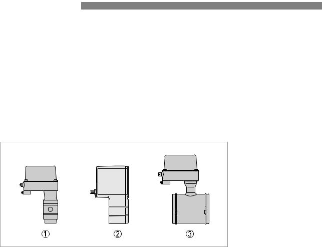
2.2 Device description
BATCHFLUX 5500 C 
Your measuring device is supplied ready for operation. The factory settings for the operating data have been made in accordance with your order specifications.
The following compact versions are available:
•Version 1: converter directly mounted on cast sensor housing in size DN2.5..6
•Version 2: converter and sensor in solid cast BNG construction for DN10 and DN 15
•Version 3: converter mounted on conventional sensor construction (DN25 and DN40)
Figure 2-2: Device version
1DN2.5 - 4 - 6 ( 1/10 -1 /6 -1 /4 " ).
2DN10 - DN15 ( 3/8 -1 /2 " ).
3DN25 - DN40 ( 1 - 11 /2 " ).
8 |
www.krohne.com |
05/2014 - 4000827703 - HB BATCHFLUX 5500 R03 en |
|
|
DEVICE DESCRIPTION 2 |
|
BATCHFLUX 5500 C |
|
|
|
|
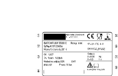
2.3 Nameplate
Figure 2-3: Nameplate
1Name and address of the manufacturer
2Type designation, S/N nr and year of manufacturing
3Calibration and device data
4Tag number
5Marking ( ao. CE and 3-A logo )
6Electrical values and software revision nr.
7Output data
8Additional info ( e.g. manufacturer website)
05/2014 - 4000827703 - HB BATCHFLUX 5500 R03 en |
www.krohne.com |
9 |

3 INSTALLATION |
BATCHFLUX 5500 C |
|
3.1 General notes on installation
INFORMATION!
Inspect the packaging carefully for damages or signs of rough handling. Report damage to the carrier and to the local office of the manufacturer.
INFORMATION!
Do a check of the packing list to make sure that you have all the elements given in the order.
INFORMATION!
Look at the device nameplate to ensure that the device is delivered according to your order. Check for the correct supply voltage printed on the nameplate.
3.2Storage
•Store the device in a dry and dust-free location.
•Avoid lasting direct exposure to the sun.
•Store the device in its original packaging.
•Storage temperature: -50 ...+70°C / -58...+158°F
3.3Pre-installation requirements
Make sure that you have all necessary tools available:
•Small wrench (M5) for connection to ground
•Torque wrench for installing flowmeter in pipeline
Assecoires necessary for the correct installations are available on request at the manufacturer
Make sure that these accesoires are available before starting installation;
•O- ring / L-ring gasket
•Special pipe flanges
•Stud bolt with lockwasher, plain washer and nut
INFORMATION!
To facilitate servicing and/or exchanging of the device, please note that:
it must be possible to shut off the flow through the pipeline ( control valve upstream in pipeline). Drain the pipeline before removing device ( provide drain valve)
10 |
www.krohne.com |
05/2014 - 4000827703 - HB BATCHFLUX 5500 R03 en |
 Loading...