


Service and Maintenance Manual
Models
X14JH
X14J - X390AJ
X17J
X19J - X550AJ X23J - X700AJ
P/N - 3121448
June 6, 2012
INTRODUCTION
SECTION A. INTRODUCTION - MAINTENANCE SAFETY PRECAUTIONS
A GENERAL |
C MAINTENANCE |
This section contains the general safety precautions which must be observed during maintenance of the aerial platform. It is of utmost importance that maintenance personnel pay strict attention to these warnings and precautions to avoid possible injury to themselves or others, or damage to the equipment. A maintenance program must be followed to ensure that the machine is safe to operate.
MODIFICATION OR ALTERATION OF AN AERIAL WORK PLATFORM SHALL BE MADE ONLY WITH WRITTEN PERMISSION FROM THE MANUFACTURER.
The specific precautions to be observed during maintenance are inserted at the appropriate point in the manual. These precautions are, for the most part, those that apply when servicing hydraulic and larger machine component parts.
Your safety, and that of others, is the first consideration when engaging in the maintenance of equipment. Always be conscious of weight. Never attempt to move heavy parts without the aid of a mechanical device. Do not allow heavy objects to rest in an unstable position. When raising a portion of the equipment, ensure that adequate support is provided.
SINCE THE MACHINE MANUFACTURER HAS NO DIRECT CONTROL OVER THE FIELD INSPECTION AND MAINTENANCE, SAFETY IN THIS AREA IS THE RESPONSIBILITY OF THE OWNER/OPERATOR.
B HYDRAULIC SYSTEM SAFETY
It should be noted that the machines hydraulic systems operate at extremely high potentially dangerous pressures. Every effort should be made to relieve any system pressure prior to disconnecting or removing any portion of the system.
FAILURE TO COMPLY WITH SAFETY PRECAUTIONS LISTED IN THIS SECTION COULD RESULT IN MACHINE DAMAGE, PERSONNEL INJURY OR DEATH AND IS A SAFETY VIOLATION.
•ENSURE REPLACEMENT PARTS OR COMPONENTS ARE IDENTICAL OR EQUIVALENT TO ORIGINAL PARTS OR COMPONENTS.
•NO SMOKING IS MANDATORY. NEVER REFUEL DURING ELECTRICAL STORMS. ENSURE THAT FUEL CAP IS CLOSED AND SECURE AT ALL OTHER TIMES.
•REMOVE ALL RINGS, WATCHES AND JEWELRY WHEN PERFORMING ANY MAINTENANCE.
•DO NOT WEAR LONG HAIR UNRESTRAINED, OR LOOSE-FITTING CLOTHING AND NECKTIES WHICH ARE APT TO BECOME CAUGHT ON OR ENTANGLED IN EQUIPMENT.
•OBSERVE AND OBEY ALL WARNINGS AND CAUTIONS ON MACHINE AND IN SERVICEMANUAL.
•KEEP OIL, GREASE, WATER, ETC. WIPED FROM STANDING SURFACES AND HAND HOLDS.
•USE CAUTION WHEN CHECKING A HOT, PRESSURIZED COOLANT SYSTEM.
•NEVER WORK UNDER AN ELEVATED BOOM UNTIL BOOM HAS BEEN SAFELY RESTRAINED FROM ANY MOVEMENT BY BLOCKING OR OVERHEAD SLING, OR BOOM SAFETY PROP HAS BEEN ENGAGED.
•BEFORE MAKING ADJUSTMENTS, LUBRICATING OR PERFORMING ANY OTHER MAINTENANCE, SHUT OFF ALL POWER CONTROLS.
•BATTERY SHOULD ALWAYS BE DISCONNECTEDDURING REPLACEMENT OF ELECTRICAL COMPONENTS.
•KEEP ALL SUPPORT EQUIPMENT AND ATTACHMENTS STOWED IN THEIR PROPER PLACE.
•USE ONLY APPROVED, NONFLAMMABLE CLEANING SOLVENTS.
3121448 |
– JLG Lift – |
A-1 |

INTRODUCTION
REVISON LOG
Original Issue |
- June 6, 2012 |
A-2 |
– JLG Lift – |
3121448 |

TABLE OF CONTENTS
SECTION NO. |
TITLE |
PAGE NO. |
SECTION A - INTRODUCTION - MAINTENANCE SAFETY PRECAUTIONS
A General . . . . . . . . . . . . . . . . . . . . . . . . . . . . . . . . . . . . . . . . . . . . . . . . . . . . . . . . . . . . . . . . . . . . . .A-1 B Hydraulic System Safety . . . . . . . . . . . . . . . . . . . . . . . . . . . . . . . . . . . . . . . . . . . . . . . . . . . . . . . . .A-1 C Maintenance . . . . . . . . . . . . . . . . . . . . . . . . . . . . . . . . . . . . . . . . . . . . . . . . . . . . . . . . . . . . . . . . . .A-1
SECTION 1 - SPECIFICATIONS
1.1 Capacities . . . . . . . . . . . . . . . . . . . . . . . . . . . . . . . . . . . . . . . . . . . . . . . . . . . . . . . . . . . . . . . . . . . .1-1 1.2 Tracks . . . . . . . . . . . . . . . . . . . . . . . . . . . . . . . . . . . . . . . . . . . . . . . . . . . . . . . . . . . . . . . . . . . . . . .1-2 1.3 Engine Data . . . . . . . . . . . . . . . . . . . . . . . . . . . . . . . . . . . . . . . . . . . . . . . . . . . . . . . . . . . . . . . . . . .1-3 HONDA ENGINE GX270 - GX390 . . . . . . . . . . . . . . . . . . . . . . . . . . . . . . . . . . . . . . . . . . . . . 1-3 HONDA ENGINE IGX440 . . . . . . . . . . . . . . . . . . . . . . . . . . . . . . . . . . . . . . . . . . . . . . . . . . . 1-4 HATZ ENGINE 1B30 - 1B40. . . . . . . . . . . . . . . . . . . . . . . . . . . . . . . . . . . . . . . . . . . . . . . . . . 1-5 PERKINS ENGINE 402D . . . . . . . . . . . . . . . . . . . . . . . . . . . . . . . . . . . . . . . . . . . . . . . . . . . . 1-5
1.4 Specifications and Performance Data. . . . . . . . . . . . . . . . . . . . . . . . . . . . . . . . . . . . . . . . . . . . . . .1-6 Reach Specifications. . . . . . . . . . . . . . . . . . . . . . . . . . . . . . . . . . . . . . . . . . . . . . . . . . . . . . . . . . . .1-6 Dimensional Data . . . . . . . . . . . . . . . . . . . . . . . . . . . . . . . . . . . . . . . . . . . . . . . . . . . . . . . . . . . . . .1-6 Chassis . . . . . . . . . . . . . . . . . . . . . . . . . . . . . . . . . . . . . . . . . . . . . . . . . . . . . . . . . . . . . . . . . . . . . .1-7 1.5 FUNCTION SPEEDS . . . . . . . . . . . . . . . . . . . . . . . . . . . . . . . . . . . . . . . . . . . . . . . . . . . . . . . . . . . .1-8
1.6 PRESSURE SETTINGS - PSI (BAR) . . . . . . . . . . . . . . . . . . . . . . . . . . . . . . . . . . . . . . . . . . . . . . . .1-9 1.7 SERIAL NUMBER LOCATION . . . . . . . . . . . . . . . . . . . . . . . . . . . . . . . . . . . . . . . . . . . . . . . . . . . . .1-10
SECTION 2 - GENERAL
2.1 Machine Preparation, Inspection, and Maintenance . . . . . . . . . . . . . . . . . . . . . . . . . . . . . . . . . . .2-1 General. . . . . . . . . . . . . . . . . . . . . . . . . . . . . . . . . . . . . . . . . . . . . . . . . . . . . . . . . . . . . . . . . . 2-1 Preparation, Inspection, and Maintenance . . . . . . . . . . . . . . . . . . . . . . . . . . . . . . . . . . . . . . 2-1 Pre-Start Inspection . . . . . . . . . . . . . . . . . . . . . . . . . . . . . . . . . . . . . . . . . . . . . . . . . . . . . . . . 2-1 Pre-Delivery Inspection and Frequent Inspection . . . . . . . . . . . . . . . . . . . . . . . . . . . . . . . . . 2-1 Annual Machine Inspection . . . . . . . . . . . . . . . . . . . . . . . . . . . . . . . . . . . . . . . . . . . . . . . . . . 2-1 Preventative Maintenance . . . . . . . . . . . . . . . . . . . . . . . . . . . . . . . . . . . . . . . . . . . . . . . . . . . 2-1
2.2 Service and Guidelines . . . . . . . . . . . . . . . . . . . . . . . . . . . . . . . . . . . . . . . . . . . . . . . . . . . . . . . . . .2-2 General. . . . . . . . . . . . . . . . . . . . . . . . . . . . . . . . . . . . . . . . . . . . . . . . . . . . . . . . . . . . . . . . . . 2-2 Safety and Workmanship . . . . . . . . . . . . . . . . . . . . . . . . . . . . . . . . . . . . . . . . . . . . . . . . . . . 2-2 Cleanliness. . . . . . . . . . . . . . . . . . . . . . . . . . . . . . . . . . . . . . . . . . . . . . . . . . . . . . . . . . . . . . . 2-2 Components Removal and Installation . . . . . . . . . . . . . . . . . . . . . . . . . . . . . . . . . . . . . . . . . 2-2 Component Disassembly and Reassembly . . . . . . . . . . . . . . . . . . . . . . . . . . . . . . . . . . . . . 2-3 Pressure-Fit Parts. . . . . . . . . . . . . . . . . . . . . . . . . . . . . . . . . . . . . . . . . . . . . . . . . . . . . . . . . . 2-3 Bearings. . . . . . . . . . . . . . . . . . . . . . . . . . . . . . . . . . . . . . . . . . . . . . . . . . . . . . . . . . . . . . . . . 2-3 Gaskets . . . . . . . . . . . . . . . . . . . . . . . . . . . . . . . . . . . . . . . . . . . . . . . . . . . . . . . . . . . . . . . . . 2-3 Bolt Usage and Torque Application . . . . . . . . . . . . . . . . . . . . . . . . . . . . . . . . . . . . . . . . . . . 2-3 Hydraulic Lines and Electrical Wiring . . . . . . . . . . . . . . . . . . . . . . . . . . . . . . . . . . . . . . . . . . 2-3 Hydraulic System. . . . . . . . . . . . . . . . . . . . . . . . . . . . . . . . . . . . . . . . . . . . . . . . . . . . . . . . . . 2-3 Lubrication . . . . . . . . . . . . . . . . . . . . . . . . . . . . . . . . . . . . . . . . . . . . . . . . . . . . . . . . . . . . . . . 2-3 Battery . . . . . . . . . . . . . . . . . . . . . . . . . . . . . . . . . . . . . . . . . . . . . . . . . . . . . . . . . . . . . . . . . . 2-3 Lubrication and Servicing . . . . . . . . . . . . . . . . . . . . . . . . . . . . . . . . . . . . . . . . . . . . . . . . . . . 2-3
2.3 Lubrication and Information . . . . . . . . . . . . . . . . . . . . . . . . . . . . . . . . . . . . . . . . . . . . . . . . . . . . . .2-3 Hydraulic System. . . . . . . . . . . . . . . . . . . . . . . . . . . . . . . . . . . . . . . . . . . . . . . . . . . . . . . . . . 2-3 Hydraulic Oil . . . . . . . . . . . . . . . . . . . . . . . . . . . . . . . . . . . . . . . . . . . . . . . . . . . . . . . . . . . . . 2-4 Changing Hydraulic Oil . . . . . . . . . . . . . . . . . . . . . . . . . . . . . . . . . . . . . . . . . . . . . . . . . . . . . 2-4 Lubrication Specifications . . . . . . . . . . . . . . . . . . . . . . . . . . . . . . . . . . . . . . . . . . . . . . . . . . . 2-4
2.4 Cylinder Drift Test . . . . . . . . . . . . . . . . . . . . . . . . . . . . . . . . . . . . . . . . . . . . . . . . . . . . . . . . . . . . . .2-4 Cylinder Drift . . . . . . . . . . . . . . . . . . . . . . . . . . . . . . . . . . . . . . . . . . . . . . . . . . . . . . . . . . . . . 2-4 2.5 Pins and Composite Bearing Repair Guidelines . . . . . . . . . . . . . . . . . . . . . . . . . . . . . . . . . . . . . .2-5
2.6 Welding on JLG Equipment . . . . . . . . . . . . . . . . . . . . . . . . . . . . . . . . . . . . . . . . . . . . . . . . . . . . . .2-5 Do the Following When Welding on JLG Equipment . . . . . . . . . . . . . . . . . . . . . . . . . . . . . . 2-5 Do NOT Do the Following When Welding on JLG Equipment . . . . . . . . . . . . . . . . . . . . . . . 2-5
3121448 |
– JLG Lift – |
i |

TABLE OF CONTENTS
SECTION NO. |
TITLE |
PAGE NO. |
SECTION 3 - CHASSIS & TURNTABLE
3.1 RUBBER TRACK MAINTENANCE. . . . . . . . . . . . . . . . . . . . . . . . . . . . . . . . . . . . . . . . . . . . . . . . . .3-1 Checking track tension . . . . . . . . . . . . . . . . . . . . . . . . . . . . . . . . . . . . . . . . . . . . . . . . . . . . . 3-1 Operations for loosening/tightening the track. . . . . . . . . . . . . . . . . . . . . . . . . . . . . . . . . . . . 3-1 Checking The Rubber Tracks . . . . . . . . . . . . . . . . . . . . . . . . . . . . . . . . . . . . . . . . . . . . . . . . 3-2 Replacing The Rubber Tracks . . . . . . . . . . . . . . . . . . . . . . . . . . . . . . . . . . . . . . . . . . . . . . . . 3-3 Checking tightness of nuts and bolts . . . . . . . . . . . . . . . . . . . . . . . . . . . . . . . . . . . . . . . . . . 3-4
3.2 UNDERCARRIGE COMPONENTS . . . . . . . . . . . . . . . . . . . . . . . . . . . . . . . . . . . . . . . . . . . . . . . . .3-8 Replacement roller lower wheel and tracks adjuster . . . . . . . . . . . . . . . . . . . . . . . . . . . . . . 3-8 Replacement wheel drive and Motor. . . . . . . . . . . . . . . . . . . . . . . . . . . . . . . . . . . . . . . . . . . 3-8 3.3 CYLINDERS AND ENLARGEMENT GUIDE . . . . . . . . . . . . . . . . . . . . . . . . . . . . . . . . . . . . . . . . . .3-10
3.4 DRIVE GEAR MOTOR TABLE . . . . . . . . . . . . . . . . . . . . . . . . . . . . . . . . . . . . . . . . . . . . . . . . . . . . .3-11 3.5 TRACK DRIVE - BONFIGLIOLI (MT700C077) . . . . . . . . . . . . . . . . . . . . . . . . . . . . . . . . . . . . . . . . .3-12 3.6 TRACK DRIVE - BONFIGLIOLI (2T701C2K042002) . . . . . . . . . . . . . . . . . . . . . . . . . . . . . . . . . . . .3-53 3.7 DRIVE HUB - EATON . . . . . . . . . . . . . . . . . . . . . . . . . . . . . . . . . . . . . . . . . . . . . . . . . . . . . . . . . . .3-97 3.8 SWING DRIVE (IMO) . . . . . . . . . . . . . . . . . . . . . . . . . . . . . . . . . . . . . . . . . . . . . . . . . . . . . . . . . . . .3-105 3.9 HONDA ENGINE GX270 - GX390 . . . . . . . . . . . . . . . . . . . . . . . . . . . . . . . . . . . . . . . . . . . . . . . . . .3-122 3.10 HONDA ENGINE IGX440 . . . . . . . . . . . . . . . . . . . . . . . . . . . . . . . . . . . . . . . . . . . . . . . . . . . . . . . .3-194 3.11 HATZ ENGINE . . . . . . . . . . . . . . . . . . . . . . . . . . . . . . . . . . . . . . . . . . . . . . . . . . . . . . . . . . . . . . . . .3-265 3.12 PERKINS ENGINE . . . . . . . . . . . . . . . . . . . . . . . . . . . . . . . . . . . . . . . . . . . . . . . . . . . . . . . . . . . . . .3-332 3.13 ENGINE REMOVAL . . . . . . . . . . . . . . . . . . . . . . . . . . . . . . . . . . . . . . . . . . . . . . . . . . . . . . . . . . . . .3-369 3.14 CHANGING THE ELECTRIC MOTOR . . . . . . . . . . . . . . . . . . . . . . . . . . . . . . . . . . . . . . . . . . . . . . .3-370
SECTION 4 - BOOM & PLATFORM
4.1 BOOM MAINTENANCE. . . . . . . . . . . . . . . . . . . . . . . . . . . . . . . . . . . . . . . . . . . . . . . . . . . . . . . . . .4-1 Removal of the Boom Assembly . . . . . . . . . . . . . . . . . . . . . . . . . . . . . . . . . . . . . . . . . . . . . . 4-1 Disassembly of the Main Boom. . . . . . . . . . . . . . . . . . . . . . . . . . . . . . . . . . . . . . . . . . . . . . . 4-2 Inspection . . . . . . . . . . . . . . . . . . . . . . . . . . . . . . . . . . . . . . . . . . . . . . . . . . . . . . . . . . . . . . . 4-2 Assembly of the Main Boom . . . . . . . . . . . . . . . . . . . . . . . . . . . . . . . . . . . . . . . . . . . . . . . . . 4-2 Installation of the Boom Assembly . . . . . . . . . . . . . . . . . . . . . . . . . . . . . . . . . . . . . . . . . . . . 4-4
4.2 BOOM DISASSEMBLY X23J - X700AJ . . . . . . . . . . . . . . . . . . . . . . . . . . . . . . . . . . . . . . . . . . . . . .4-7 4.3 INSPECTION . . . . . . . . . . . . . . . . . . . . . . . . . . . . . . . . . . . . . . . . . . . . . . . . . . . . . . . . . . . . . . . . . .4-11 Checking wear and deformation of ropes and pulleys . . . . . . . . . . . . . . . . . . . . . . . . . . . . . 4-11 Assembly . . . . . . . . . . . . . . . . . . . . . . . . . . . . . . . . . . . . . . . . . . . . . . . . . . . . . . . . . . . . . . . . 4-11 Installation . . . . . . . . . . . . . . . . . . . . . . . . . . . . . . . . . . . . . . . . . . . . . . . . . . . . . . . . . . . . . . . 4-13 Three month inspection. . . . . . . . . . . . . . . . . . . . . . . . . . . . . . . . . . . . . . . . . . . . . . . . . . . . . 4-14
4.4 ROPES TENSION ADJUSTMENT PROCEDURE . . . . . . . . . . . . . . . . . . . . . . . . . . . . . . . . . . . . . .4-14 4.5 ROTARY ACTUATOR . . . . . . . . . . . . . . . . . . . . . . . . . . . . . . . . . . . . . . . . . . . . . . . . . . . . . . . . . . .4-16 4.6 PLATFORM REMOVAL/INSTALLATION . . . . . . . . . . . . . . . . . . . . . . . . . . . . . . . . . . . . . . . . . . . . .4-24 4.7 LOAD CELL AND FOOTSWITCH REMOVAL/INSTALLATION . . . . . . . . . . . . . . . . . . . . . . . . . . . .4-25
SECTION 5 - HYDRAULICS
5.1 CYLINDER REPAIR . . . . . . . . . . . . . . . . . . . . . . . . . . . . . . . . . . . . . . . . . . . . . . . . . . . . . . . . . . . . .5-1 5.2 REPLACEMENT HYDRAULIC PUMP . . . . . . . . . . . . . . . . . . . . . . . . . . . . . . . . . . . . . . . . . . . . . . .5-21 5.3 FUNCTION PUMP . . . . . . . . . . . . . . . . . . . . . . . . . . . . . . . . . . . . . . . . . . . . . . . . . . . . . . . . . . . . . .5-22 5.4 HYDRAULIC COMPONENT START-UP PROCEDURES AND RECOMMENDATIONS. . . . . . . . . .5-34 5.5 PRESSURE SETTING PROCEDURE . . . . . . . . . . . . . . . . . . . . . . . . . . . . . . . . . . . . . . . . . . . . . . .5-36 5.6 HYDRAULIC SCHEMATIC. . . . . . . . . . . . . . . . . . . . . . . . . . . . . . . . . . . . . . . . . . . . . . . . . . . . . . . .5-42
SECTION 6 - JLG CONTROL SYSTEM
6.1 |
Introduction . . . . . . . . . . . . . . . . . . . . . . . . . . . . . . . . . . . . . . . . . . . . . . . . . . . . . . . . . . . . . . . . . . . |
6-1 |
6.2 |
PLATFORM/REMOTE CONTROL STATION LCD DISPLAY . . . . . . . . . . . . . . . . . . . . . . . . . . . . . . |
6-2 |
6.3 |
CANBUS COMMUNICATIONS . . . . . . . . . . . . . . . . . . . . . . . . . . . . . . . . . . . . . . . . . . . . . . . . . . . . |
6-6 |
|
MODULE FLASHING CODE . . . . . . . . . . . . . . . . . . . . . . . . . . . . . . . . . . . . . . . . . . . . . . . . . |
6-9 |
|
Remote Control Operation . . . . . . . . . . . . . . . . . . . . . . . . . . . . . . . . . . . . . . . . . . . . . . . . . . |
6-12 |
6.4 |
CALIBRATION INSTRUCTIONS . . . . . . . . . . . . . . . . . . . . . . . . . . . . . . . . . . . . . . . . . . . . . . . . . . . |
6-13 |
6.5 |
PLATFORM REMOTE CONTROL SERVICE . . . . . . . . . . . . . . . . . . . . . . . . . . . . . . . . . . . . . . . . . . |
6-14 |
ii |
– JLG Lift – |
3121448 |

TABLE OF CONTENTS
SECTION NO. |
TITLE |
PAGE NO. |
6.6 |
MENU INPUT. . . . . . . . . . . . . . . . . . . . . . . . . . . . . . . . . . . . . . . . . . . . . . . . . . . . . . . . . . . . . . . |
. . .6-25 |
6.7 |
LANGUAGE . . . . . . . . . . . . . . . . . . . . . . . . . . . . . . . . . . . . . . . . . . . . . . . . . . . . . . . . . . . . . . . . . |
. .6-35 |
6.8 |
MENU ERRORS. . . . . . . . . . . . . . . . . . . . . . . . . . . . . . . . . . . . . . . . . . . . . . . . . . . . . . . . . . . . . . |
. .6-36 |
6.9 |
RAMPS. . . . . . . . . . . . . . . . . . . . . . . . . . . . . . . . . . . . . . . . . . . . . . . . . . . . . . . . . . . . . . . . . . . . . |
. .6-45 |
6.10 |
CURRENTS . . . . . . . . . . . . . . . . . . . . . . . . . . . . . . . . . . . . . . . . . . . . . . . . . . . . . . . . . . . . . . . . . |
. .6-46 |
6.11 |
WORKING HOURS . . . . . . . . . . . . . . . . . . . . . . . . . . . . . . . . . . . . . . . . . . . . . . . . . . . . . . . . . . . |
. .6-48 |
6.12 |
MACHINE SETUP . . . . . . . . . . . . . . . . . . . . . . . . . . . . . . . . . . . . . . . . . . . . . . . . . . . . . . . . . . . . |
. .6-50 |
6.13 |
JOYSTICK . . . . . . . . . . . . . . . . . . . . . . . . . . . . . . . . . . . . . . . . . . . . . . . . . . . . . . . . . . . . . . . . . . |
. .6-61 |
6.14 |
CALIBRATING JOYSTICK . . . . . . . . . . . . . . . . . . . . . . . . . . . . . . . . . . . . . . . . . . . . . . . . . . . . . . |
. .6-62 |
6.15 |
CONFIGURATION SERIAL NUMBER RADIO REMOTE CONTROL (X17J ONLY) . . . . . . . . . . . |
. .6-63 |
SECTION 7 - BASIC ELECTRICAL INFORMATION & SCHEMATICS
7.1 DESCRIPTION FOR MODELS X14J/X390AJ-X19J/X550AJ-X23J/X700AJ. . . . . . . . . . . . . . . . . . .7-1 7.2 A - HOW TO READ THE WIRING DIAGRAMS . . . . . . . . . . . . . . . . . . . . . . . . . . . . . . . . . . . . . . . .7-2
7.3B - PHOTOCELLS - SAFETY EXCLUSION - SLEW PROXIMITY-
STABILIZERS PRESSURE SENSORS . . . . . . . . . . . . . . . . . . . . . . . . . . . . . . . . . . . . . . . . . . . . . .7-3
7.4C - AERIAL PART SAFETY CHAIN: OUTRIGGERS ALIGNED SWITCHES (ONLY X23J-X700AJ) .7-5
7.5 D - AERIAL PART SAFETY CHAIN: OUTRIGGERS SWITCHES . . . . . . . . . . . . . . . . . . . . . . . . . . .7-7
7.6E - CAN NETWORK - CYLINDERS POSITION SENSORS - REMOTE CONTROL CONNECTOR-
MODEM . . . . . . . . . . . . . . . . . . . . . . . . . . . . . . . . . . . . . . . . . . . . . . . . . . . . . . . . . . . . . . . . . . . . . .7-9 7.7 F - ROPES SWITCH - JIB POSITION SWITCH - PEDAL - LOAD CELL . . . . . . . . . . . . . . . . . . . . .7-11
7.8G - ENGINE STOP SWITCHES-ENGINE START PUSH BUTTONS (GROUND)-AERIAL MOVEMENTS
ABILITATION SWITCH (GROUND) . . . . . . . . . . . . . . . . . . . . . . . . . . . . . . . . . . . . . . . . . . . . . . . . .7-13 7.9 H - EMERGENCY DESCEND ELECTRO VALVES - OPTIONALS . . . . . . . . . . . . . . . . . . . . . . . . . .7-15 7.10 I - ELECTRIC POWER SUPPLY . . . . . . . . . . . . . . . . . . . . . . . . . . . . . . . . . . . . . . . . . . . . . . . . . . . .7-17
7.11L - GROUND PART: TRACKS - UNDERCARRIAGE WIDENING - 2° SPEED - PROPORTIONAL
ELECTRO VALVES . . . . . . . . . . . . . . . . . . . . . . . . . . . . . . . . . . . . . . . . . . . . . . . . . . . . . . . . . . . . .7-19 7.12 M - GROUND PART: OUTRIGGERS - ELECTRIC DIVERTER . . . . . . . . . . . . . . . . . . . . . . . . . . . . .7-21
7.13N - AERIAL PART: BASKET LEVELLING - BASKET ROTATION - JIB - PROPORTIONAL
ELECTRO VALVE. . . . . . . . . . . . . . . . . . . . . . . . . . . . . . . . . . . . . . . . . . . . . . . . . . . . . . . . . . . . . . .7-23 7.14 O - AERIAL PART: 1° CYLINDER - 2° CYLINDER - EXTENSION - ROTATION . . . . . . . . . . . . . . . .7-25 7.15 P1 - THERMIC ENGINE CONNEXION (GASOLINE) - X19J-X550AJ/X23J-X700AJ . . . . . . . . . . . .7-27 7.16 P2 - THERMIC ENGINE CONNEXION (DIESEL) - DIESEL ENGINE SENSORS - X23J-X700AJ . .7-29 7.17 P3 - THERMIC ENGINE CONNEXION (DIESEL) - X14J-X390AJ/X19J-X550AJ . . . . . . . . . . . . . . .7-31 7.18 P4 - THERMIC ENGINE CONNEXION (GASOLINE) - X14J-X390AJ . . . . . . . . . . . . . . . . . . . . . . .7-33 7.19 Q - 110-220 VOLT ELECTRIC POWER SUPPLY - ELECTRIC ENGINE . . . . . . . . . . . . . . . . . . . . .7-35 7.20 R - DOUBLE STABILIZATION AREA WITH ROTATION SENSOR - X23J-X700AJ . . . . . . . . . . . . .7-37 7.21 DESCRIPTION FOR MODELS X14JH - X17J . . . . . . . . . . . . . . . . . . . . . . . . . . . . . . . . . . . . . . . . .7-41 7.22 A - HOW TO READ THE WIRING DIAGRAMS . . . . . . . . . . . . . . . . . . . . . . . . . . . . . . . . . . . . . . . .7-42
7.23B - PHOTOCELLS - SAFETY EXCLUSION - SLEW PROXIMITY - STABILIZERS PRESSURE
SENSORS - 1° ARM SWITCH . . . . . . . . . . . . . . . . . . . . . . . . . . . . . . . . . . . . . . . . . . . . . . . . . . . . .7-43 7.24 C - AERIAL PART SAFETY CHAIN: OUTRIGGERS SWITCHES . . . . . . . . . . . . . . . . . . . . . . . . . . .7-45 7.25 D - CAN NETWORK - JIB POSITION SWITCH - MODEM. . . . . . . . . . . . . . . . . . . . . . . . . . . . . . . .7-47 7.26 E - HANDLE SWITCHES - LOAD CELL - PEDAL . . . . . . . . . . . . . . . . . . . . . . . . . . . . . . . . . . . . . .7-49
7.27F - ENGINE STOP SWITCHES - ENGINE START PUSH BUTTONS (GROUND) - AERIAL
MOVEMENTS ABILITATION SWITCH (GROUND) . . . . . . . . . . . . . . . . . . . . . . . . . . . . . . . . . . . . .7-51
7.28G - EMERGENCY DESCEND ELECTRO VALVES - REMOTE CONTROL BATTERY
CHARGER - OPTIONALS . . . . . . . . . . . . . . . . . . . . . . . . . . . . . . . . . . . . . . . . . . . . . . . . . . . . . . . .7-53 7.29 H - ELECTRIC POWER SUPPLY . . . . . . . . . . . . . . . . . . . . . . . . . . . . . . . . . . . . . . . . . . . . . . . . . . .7-55
7.30I - GROUND PART: TRACKS - UNDERCARRIAGE WIDENING - 2° SPEED - PROPORTIONAL
ELECTRO VALVES . . . . . . . . . . . . . . . . . . . . . . . . . . . . . . . . . . . . . . . . . . . . . . . . . . . . . . . . . . . . .7-57
7.31L - GROUND PART: OUTRIGGERS - ELECTRIC DIVERTER - AERIAL SAFETY
ELECTRO VALVE. . . . . . . . . . . . . . . . . . . . . . . . . . . . . . . . . . . . . . . . . . . . . . . . . . . . . . . . . . . . . . .7-59 7.32 M1 - THERMIC ENGINE CONNEXION (GASOLINE) . . . . . . . . . . . . . . . . . . . . . . . . . . . . . . . . . . .7-61 7.33 M2 - THERMIC ENGINE CONNEXION (DIESEL) . . . . . . . . . . . . . . . . . . . . . . . . . . . . . . . . . . . . . .7-63 7.34 N - 220 VOLT ELECTRIC POWER SUPPLY - ELECTRIC ENGINE . . . . . . . . . . . . . . . . . . . . . . . . .7-65 7.35 ELECTRIC SCHEDULES LAYOUT . . . . . . . . . . . . . . . . . . . . . . . . . . . . . . . . . . . . . . . . . . . . . . . . .7-67
3121448 |
– JLG Lift – |
iii |

TABLE OF CONTENTS
SECTION NO. |
TITLE |
PAGE NO. |
7.36 COMPONENTS LOCATION . . . . . . . . . . . . . . . . . . . . . . . . . . . . . . . . . . . . . . . . . . . . . . . . . . . . . .7-68 7.37 Z1 - BATTERY PACK AND BMS . . . . . . . . . . . . . . . . . . . . . . . . . . . . . . . . . . . . . . . . . . . . . . . . . . .7-69 7.38 Z2 - RELAIS - FUSES - 12V BATTERY . . . . . . . . . . . . . . . . . . . . . . . . . . . . . . . . . . . . . . . . . . . . . .7-71 7.39 Z3 - CAN BUS LINE - MAIN SWITCH - IGNITION KEY . . . . . . . . . . . . . . . . . . . . . . . . . . . . . . . . . .7-73 7.40 Z4 - INVERTER - MOTOR - ECM. . . . . . . . . . . . . . . . . . . . . . . . . . . . . . . . . . . . . . . . . . . . . . . . . . .7-75
iv |
– JLG Lift – |
3121448 |

SECTION 1 - SPECIFICATIONS
SECTION 1. SPECIFICATIONS
1.1 CAPACITIES
Table 1-1. DRIBE HUB CAPACITIES
|
TYPE DRIBE HUB |
SPEED |
|
MACHINE |
|
|
CAPACITIES |
|||
|
|
|
|
|
|
|
|
|
|
|
|
|
|
|
|
|
|
|
|
|
|
|
BONFIGLIOLI |
1V |
|
X14JH |
|
0,340 kg (0,75 lbs) |
||||
|
7C 00 1 G 40 HC0 5.25 065RT01P 3WH LZ |
|
X14J-X390AJ |
|
||||||
|
|
|
|
|
|
|
||||
|
|
|
|
|
|
|
|
|
|
|
|
BONFIGLIOLI |
1V |
|
X17J |
|
0,340 kg (0,75 lbs) |
||||
|
7C 00 1G 40 HC0 5.25 080RT01P 3WI1 LA |
|
X19J-X550AJ |
|
||||||
|
|
|
|
|
|
|
||||
|
|
|
|
|
|
|
|
|
|
|
|
BONFIGLIOLI |
2V |
|
X23J-X700AJ |
|
0,620 kg (1,37 lbs) |
||||
|
7C 01 2 K A L 53 G018VP34 LA |
|
|
|||||||
|
|
|
|
|
|
|
|
|
||
|
|
|
|
|
|
|
|
|
|
|
|
|
|
|
|
X14JH |
|
|
|
|
|
|
EATON |
2V |
|
X17J |
|
|
NO OIL |
|||
|
|
X14J-X390AJ |
|
|
||||||
|
|
|
|
|
|
|
|
|
||
|
|
|
|
|
X19J-X550AJ |
|
|
|
|
|
|
|
|
|
|
|
|
|
|
|
|
|
Table 1-2. HYDRAULIC & FUEL TANK CAPACITIES |
|
|
|
|
|||||
|
|
|
|
|
|
|
|
|||
|
MACHINE |
|
HYDRAULIC OIL TANK |
|
FUEL TANK |
|
||||
|
|
CAPACITY |
|
|
|
|
|
|
||
|
|
|
|
|
|
|
|
|
||
|
|
|
|
|
|
|
|
|
|
|
|
|
|
|
|
|
|
|
|
|
|
|
|
|
|
|
|
GASOLINE |
|
DIESEL |
|
|
|
|
|
|
|
|
|
|
|
||
|
X14JH |
|
5,49 gal (25 L) |
|
1.4 gal (5 L) |
|
1.3 gal (5 L) |
|
||
|
|
|
|
|
|
|
|
|
||
|
X14J-X390AJ |
|
5,49 gal (25 L) |
|
1.4 gal (5 L) |
|
1.3 gal (5 L) |
|
||
|
|
|
|
|
|
|
|
|
||
|
X17J |
|
5,49 gal (25 L) |
|
1.5 gal (5.9 L) |
|
1.3 gal (5 L) |
|
||
|
|
|
|
|
|
|
|
|
||
|
X19J-X550AJ |
|
5,49 gal (25 L) |
|
1.5 gal (5.9 L) |
|
1.3 gal (5 L) |
|
||
|
|
|
|
|
|
|
|
|
||
|
X23J-X700AJ |
|
10,55 gal (48L) |
|
1.5 gal (5.9L) |
|
3.4 gal (13L) |
|
||
|
|
|
|
|
|
|
|
|
|
|
3121448 |
– JLG Lift – |
1-1 |

SECTION 1 - SPECIFICATIONS
1.2 TRACKS
Table 1-3. Track Specifications
MODEL |
TRACK DIMENSIONS |
|
MACHINE |
||
|
||
|
|
|
X14JH |
|
|
|
|
|
X14J-X390AJ |
180x37x72 |
|
|
||
X17J |
|
|
|
|
|
X19J-X550AJ |
|
|
|
|
|
X23J-X700AJ |
230x39x96 |
|
|
|
Table 1-4. Ground bearing pressure
PRESSURES AND REACTIONS TO THE GROUND
MODEL |
|
ON TRACKS |
|
|
|
ON OUTRIGGER |
|
||
|
|
|
|
|
|
|
|
|
|
|
Reaction |
Pressure |
|
Reaction |
Pressure |
||||
|
[daN] - [lbf] |
[daN/cm²] - [PSI] |
|
[daN] - [lbf] |
[daN/cm²] - [PSI] |
||||
X14J-H |
1670 daN |
3754 lbf |
0,5 daN/cm² |
7,11 |
PSI |
1330 daN |
2989 lbf |
1,9 daN/cm² |
27 PSI |
|
|
|
|
|
|
|
|
|
|
X14J |
1400 daN |
3147 lbf |
0,4 daN/cm² |
5,69 |
PSI |
1200 daN |
2697 lbf |
1,7 daN/cm² |
24,1 PSI |
|
|
|
|
|
|
|
|
|
|
X390AJ |
1658 daN |
3727 lbf |
0,5 daN/cm² |
7,11 |
PSI |
1200 daN |
2697 lbf |
1,7 daN/cm² |
24,1 PSI |
|
|
|
|
|
|
|
|
|
|
X17J |
2100 daN |
4720 lbf |
0,62 daN/cm² |
8,82 PSI |
1450 daN |
3259 lbf |
2,0 daN/cm² |
28,4 PSI |
|
|
|
|
|
|
|
|
|
|
|
X19J - X550AJ |
2100 daN |
4720 lbf |
0,62 daN/cm² |
8,82 |
PSI |
1330 daN |
2989 lbf |
1,9 daN/cm² |
27 PSI |
|
|
|
|
|
|
|
|
|
|
X23J - X700AJ |
3000 daN |
6744 lbf |
0,48 daN/cm² |
6,83 |
PSI |
2100 daN |
4720 lbf |
3 daN/cm² |
42,6 PSI |
|
|
|
|
|
|
|
|
|
|
1-2 |
– JLG Lift – |
3121448 |
SECTION 1 - SPECIFICATIONS
1.3 ENGINE DATA
NOTE: RPM Tolerances are ± 50.
HONDA ENGINE GX270 - GX390
Table 1-5. SPECIFICATIONS HONDA ENGINE GX270-GX390
Model |
GX270 |
GX390UT2 |
|
|
|
Description code |
GCALK |
GCBCT |
|
|
|
Type |
4 stroke, overhead valve, single cylinder, inclined by 25° |
|
|
|
|
Displacement |
270 cm3 (16.5 cu–in) |
389 cm3 (23.7 cu–in) |
|
|
|
Bore x stroke |
77.0 x 58.0 mm (3.0 x 2.3 in) |
88.0 x 64.0 mm (3.5 x 2.5 in) |
|
|
|
Net power (SAE J1349)*1 |
6.7 kW (9 HP) / 3,600 min-1 (rpm) |
8.7 kW (11.7 HP) / 3,600 min-1 (rpm) |
|
|
|
Continuous rated power |
N.A. |
7.0 kW (9.4 HP) / 3,600 min-1 (rpm) |
|
|
|
Maximum net torque (SAE J1349)*1 |
19.5 N·m (1.95 kg·m, 14ft·lb) / 2,500 |
26.5 N·m (2.7 kgf·m, 19.5 lbf·ft) / 2,500 min- |
|
min-1 (rpm) |
1 (rpm) |
|
|
|
Compression ratio |
8.2 : 1 |
8.2 ± 0.2: 1 |
|
|
|
Fuel consumption (at continuous |
313 g/kWh (230 g/HPh, 0,51 lb/HPh) |
3.5 Liters (0.92 US gal, 0.77 Imp gal) / h |
rat-ed power) |
|
|
|
|
|
Ignition system |
C.D.I.(Capacitor Discharge Ignition) type magneto ignition |
|
|
|
|
Ignition timing |
B.T.D.C. 20° (fixed) |
B.T.D.C. 10° / 1,400min-1 (rpm) |
|
|
|
Spark advancer performance |
N.A. |
B.T.D.C. 10°- 22° |
|
|
|
Spark plug |
BPR6ES (NGK) / W20EPR-U (DENSO) |
|
|
|
|
Lubrication system |
Forced splash |
|
|
|
|
Oil capacity |
1.1 Liters (1.16 US qt, 0.97 Imp qt) |
|
|
|
|
Recommended oil |
SAE 10W-30 API service classification SE or later |
|
|
|
|
Cooling system |
Forced air |
|
|
|
|
Starting system |
Ignition exciter coil circuit open |
|
|
|
|
Carburetor |
Horizontal type, butterfly valve |
|
|
|
|
Air cleaner |
Dual element type, Cyclone type, Oil bath type, Low profile type |
|
|
|
|
Governor |
Mechanical centrifugal |
|
|
|
|
Breather system |
Reed valve type |
|
|
|
|
Fuel used |
Unleaded gasoline with a pump octane rating 86 or higher |
|
|
|
|
3121448 |
– JLG Lift – |
1-3 |

SECTION 1 - SPECIFICATIONS
HONDA ENGINE IGX440
Table 1-6. SPECIFICATIONS HONDA ENGINE iGX440 |
|
|
|
Model |
iGX440U |
|
|
Description code |
GCAWK |
|
|
Type |
4-stroke, overhead camshaft, single cylinder, inclined by 15° |
|
|
Displacement |
438 cm3 (26.7cu-in) |
Bore x stroke |
88.0 x 72.1 mm (3.46 x 2.84 in) |
|
|
Maximum horsepower |
11.2 kW (15.2 HP) / 3,600 min-1 (rpm) |
Recommended maximum operation bhp |
8.0 kW (10.8 HP) / 3,600 min-1 (rpm) |
Maximum torque |
29.8 N·m (3.0 kgf·m, 22 lbf·ft)/2,500 min-1 (rpm) |
Compression ratio |
8.1 : 1 |
|
|
Minimum fuel consumption |
328 g/kW·h (241 g/HP·h, 0.53 lb/HP·h) |
|
|
Ignition system |
CDI |
|
|
Ignition timing (at no load) |
10° B.T.D.C./1,400 min-1 (rpm) |
|
13° B.T.D.C./3,600 min-1 (rpm) |
Spark plug |
BKR7E-E (NGK), K22PR-UR (DENSO) |
|
|
Lubrication system |
Forced splash type |
|
|
Oil capacity |
1.10 l (1.16 US qt, 0.97 lmp qt) |
|
|
Cooling system |
Forced air |
|
|
Starting system |
Recoil and starter motor |
|
|
Stopping system |
Ignition primary circuit open |
|
|
Carburetor |
Horizontal type batter fly valve |
|
|
Air cleaner |
Dual element type |
|
|
Governor |
STR (Self Tuning Regulator) governor |
|
|
Fuel used |
Unleaded gasoline with a pump octane rating 86 or higher |
|
|
Fuel tank capacity |
6.5 l (1.72 US gal, 1.43 lmp gal) |
|
|
1-4 |
– JLG Lift – |
3121448 |

|
|
SECTION 1 - SPECIFICATIONS |
|||
|
|
|
|
|
|
|
HATZ ENGINE 1B30 - 1B40 |
|
|
|
|
|
Table 1-7. SPECIFICATIONS HATZ ENGINE 1B30-1B40 |
|
|
||
|
|
|
|
|
|
|
Type |
1B30 |
|
1B40 |
|
|
|
|
|
|
|
|
Design |
Air-cooled four-stroke diesel engine |
|
||
|
|
|
|
|
|
|
Combustion system |
Direct injection |
|
|
|
|
|
|
|
|
|
|
Number of cylinders |
1 |
|
1 |
|
|
|
|
|
|
|
|
Bore / stroke |
80 / 69 mm |
|
88 / 76 mm |
|
|
|
|
|
|
|
|
Displacement |
347 cm3 |
|
462 cm3 |
|
|
Lubricating oil capacity without oil sump with oil |
1.1 1) l, approx. |
|
1.5 1) l, approx. |
|
|
sump |
2.8 1) l, approx. |
|
3.2 1) l, approx. |
|
|
Difference between “max” and “min” levels without |
0.5 1) l, approx. |
|
0.8 1) l, approx. |
|
|
oil sump with oil sump |
1.8 1) l, approx. |
|
2.2 1) l, approx. |
|
|
Lubricating oil consumption (after running in) |
1% of fuel consumption at full load max.) |
|
||
|
|
|
|
||
|
Lubricating oil pressure (oil temperature 100 °C) |
2.5 bars at 3000 r.p.m. (approx.) |
|
||
|
|
|
|
|
|
|
Direction of rotation, power take-off end |
anti-clockwise |
|
|
|
|
|
|
|
|
|
|
Valve clearance 10 - 30 °C |
0.10 mm |
|
0.10 mm |
|
|
Inlet and exhaust valve |
|
|
|
|
|
or automatically 2) |
|
|
||
|
|
|
|
||
|
Max. tilt angle in operation, in direction |
Flywheel 25° down 3) all other directions 35°3) |
|
||
|
Weight (incl. fuel tank, air-cleaner, exhaust silencer, |
40 kg |
|
55 kg |
|
|
recoil starter and electric starter) |
approx. |
|
approx. |
|
|
|
|
|
|
|
|
Battery capacity |
max. 12 V / 60 Amp/h |
|
|
|
|
|
|
|
|
|
PERKINS ENGINE 402D
Table 1-8. SPECIFICATIONS PERKINS ENGINE 402D
|
|
Type |
402D-05 Engine |
|
|
Maximum Operating Speed (rpm) |
3600 rpm |
|
|
|
|
Cylinders and Arrangement |
In-Line two cylinder |
|
|
|
|
Bore |
67 mm (2.64 inch) |
|
|
Stroke |
72 mm (2.83 inch) |
|
|
Displacement |
0.507 L (30.939 in3) |
|
|
Aspiration |
NA(1) |
Compression Ratio |
23.5:1 |
|
|
Firing Order |
1-2 |
|
|
Rotation that is viewed from the flywheel |
Counterclockwise |
|
|
|
|
Valve Lash Setting (Inlet) |
0.20 mm (0.008 inch) |
|
|
Valve Lash Setting (Exhaust) |
0.20 mm (0.008 inch) |
|
|
Injection |
Indirect |
|
|
3121448 |
– JLG Lift – |
1-5 |

SECTION 1 - SPECIFICATIONS
1.4SPECIFICATIONS AND PERFORMANCE DATA
Reach Specifications
Table 1-9. Reach Specifications
|
X14J |
X14J-H |
X17J |
X19J |
X23J |
|
|
|
|
|
|
|
|
Platform Height w 120 kg capacity |
38' 7" |
(11.80 m) |
39' 2" (11.90 m) |
48' 5" (14.81 m) |
54' 6" (16.67 m) |
69' 2" (21.10 m) |
|
|
|
|
|
|
|
Platform Height w 200 kg capacity |
33' 2" |
(10.15 m) |
34'7" (10.58 m) |
43' (13.12 m) |
49' (14.96 m) |
64' 6" (19.70 m) |
|
|
|
|
|
|
|
Horizontal Outreach (Std Platform |
20' 5" |
21' 3" |
25' 1" |
19' 3" |
36' 5" |
|
w 120kg) |
(6.26 m) |
(6.50 m) |
(7.68 m) |
(5.90 m) |
(11.13 m) |
|
|
|
|
|
|
|
|
Horizontal Outreach (Std Platform |
17' 7" |
17' |
21' 1" |
14' 1" |
32' |
|
w 200kg) |
(5.42 m) |
(5.16 m) |
(6.45 m) |
(4.30 m) |
(9.75 m) |
|
|
|
|
|
|
|
|
Up & Over Height w 120 kg |
18' 3" |
19' 1" |
20' |
25' 1" |
30' 7" |
|
|
(5.58 m) |
(5.84 m) |
(6.08 m) |
(7.66 m) |
(9.38 m) |
|
|
|
|
|
|
|
|
Up & Over Height w 200 kg |
18' 1" |
15' |
19' 2" |
20' 4" |
26' 1" |
|
|
(5.52 m) |
(4.56 m) |
(5.86 m) |
(6.23 m) |
(7.96 m) |
|
|
|
|
|
|
|
|
Swing (non continuous) |
|
361° |
300° |
361° |
361° |
361° |
|
|
|
|
|
|
|
Jib - overall length |
5' 1" |
(1.56 m) |
4' 2" (1.30 m) |
4' 7" (1.43 m) |
4' 7" (1.43 m) |
4' 7" (1.43 m) |
|
|
|
|
|
|
|
Jib - range of articulation (+/-) |
83° (+0° / -83°) |
80° (+0°/-80°) |
88° (-2° / -90°) |
83° (+0° / -83°) |
85° (-1° / -86°) |
|
|
|
|
|
|
|
|
Table 1-10. Reach Specifications
|
X390AJ |
X550AJ |
X700AJ |
|
|
|
|
Platform Height |
39' 2" (11.9 m) |
55' (16.76 m) |
69' 7" (21.20 m) |
|
|
|
|
Horizontal Outreach |
22' (6.70 m) |
21' (6.40 m) |
37' (11.27 m) |
|
|
|
|
Swing (non continuous) |
360° |
360° |
360° |
|
|
|
|
Max. Platform Capacity |
440 lb (200 kg) |
440 lb (200 kg) |
440 lb (200 kg) |
|
|
|
|
Platform Rotation |
N/A |
124° (+/-62°) |
124° (+/-62°) |
|
|
|
|
Jib (Range of Articulation) |
88° (-2/-90) |
82.7° (0/-82.7) |
85° (-1/-86) |
|
|
|
|
Platform Size |
57" x 31" |
58" x 31" |
58" x 31" |
|
(1.45 x 0.77 m) |
(1.48 x 0.77 m) |
(1.48 x 0.77 m) |
|
|
|
|
Overall Width |
31" (0.77 m) |
31" (0.77 m) |
39" (0.99 m) |
|
|
|
|
Stowed Height |
6' 10" (2.07 m) |
6' 6" (1.98 m) |
6' 6" (1.98 m) |
|
|
|
|
Outrigger Footprint |
9' 7" x 9' 5" |
9' 6" x 9' 5" |
13' 1" x 13' 1" |
|
(2.9 m x 2.8 m) |
(2.8 m x 2.8 m) |
(3.9 m x 3.9 m) |
|
|
|
|
Stowed Length |
13' (3.98 m) |
14' 8" (4.47 m) |
19' 8" (6.00 m) |
|
|
|
|
Track Length |
4' 1" (1.24 m) |
4' 1" (1.24 m) |
5' 9" (1.77 m) |
|
|
|
|
Weight |
3,682 lb (1,670 kg) |
4,630 lb (2,098 kg) |
6,592 lb (2,990 kg) |
|
|
|
|
Ground Bearing Pressure |
27 psi (1.9 kg/cm2) |
27 psi (1.9 kg/cm2) |
42 psi (3.0 kg/cm2) |
Drive Speed |
.87 mph (1.4 km/h) |
.80 mph (1.3 km/h) |
.80 mph (1.3 km/h) |
|
|
|
|
Gradeability |
33% |
38% |
40% |
|
|
|
|
Slope Tolerance |
10° |
11° |
14° |
|
|
|
|
1-6 |
– JLG Lift – |
3121448 |

SECTION 1 - SPECIFICATIONS
Table 1-10. Reach Specifications
|
X390AJ |
X550AJ |
X700AJ |
|
|
|
|
Gasoline Engine |
Honda GX270 |
Honda iGX440 |
Honda iGX440 |
|
9 hp (6.7 kW) |
15 hp (11.1 kW) |
15 hp (11.1 kW) |
|
or |
|
|
|
Honda iGX390 |
|
|
|
13 hp (9.7 kW) |
|
|
|
|
|
|
Diesel Engine |
Hatz 1B30 |
Hatz 1B40 |
Perkins 402.05 |
|
7 hp (5.22 kW) |
10 hp (7.46 kW) |
14 hp (10.44 kW) |
|
|
|
|
Electric Engine |
90Ah 48V Lithium-Ion |
90Ah 48V Lithium-Ion |
90Ah 70V Lithium-Ion |
|
|
|
|
Fuel Tank Capacity (Gasoline) |
1.4 gal. (5.3 L) |
1.5 gal. (5.9 L) |
1.5 gal. (5.9 L) |
|
|
|
|
Fuel Tank Capacity (Diesel) |
1.3 gal. (5 L) |
1.3 gal. (5 L) |
3.4 gal. (13 L) |
|
|
|
|
AC Motor |
120V 60 Hz (1.2 kW) |
120V 60 Hz (1.2 kW) |
120V 60 Hz (1.2 kW) |
|
220V 60 Hz (2.2 kW) |
220V 60 Hz (2.2 kW) |
220V 60 Hz (2.2 kW) |
|
|
|
|
Dimensional Data
Table 1-11. Dimensional data
|
X14J |
X14J-H |
X17J |
X19J |
X23J |
|
|
|
|
|
|
Platform size (standard 2 persons) |
0.69mx1.30m |
0.62mx1.30m |
0.62mx1.30m |
0.69mx1.30m |
0.69mx1.30m |
|
|
|
|
|
|
Platform size (narrow one person) |
0.59mx0.79m |
0.69mx0.79m |
0.62mx0.79m |
0.59mx0.79m |
0.59mx0.79m |
|
|
|
|
|
|
Stowed width (with std. 2P platform) |
1.48 m |
1.46 m |
1.31 m |
1.48 m |
1.48 m |
|
|
|
|
|
|
Stowed width (without platform) |
0.79 m |
0.79 m |
0.79 m |
0.79 m |
0.79 m |
|
|
|
|
|
|
Stowed height (on tracks) |
2.07 m |
1.98 m |
1.99 m |
1.98 m |
1.99 m |
|
|
|
|
|
|
Stowed length (on tracks) |
4.02 m |
3.97 m |
4.53 m |
4.47 m |
6 m |
|
|
|
|
|
|
Outrigger footprint |
2.87mx2.91m |
2.70mx2.70m |
2.89mx2.88m |
2.89mx2.88m |
3.98mx3.98m |
|
|
|
|
|
|
Machine weight (with standard plat- |
1,398 kg |
1,700 kg |
2,100 kg |
2,080 kg |
2,990 kg |
form) |
|
|
|
|
|
|
|
|
|
|
|
Operating weight (with petrol |
1,430 kg |
1,740 kg |
2,152 kg |
2,106 kg |
3,100 Kg |
engine) |
|
|
|
|
|
|
|
|
|
|
|
Maximum ground bearing pressure |
1.73 kg/cm2 |
1.94 kg/cm2 |
2.09 kg/cm2 |
1.94 kg/cm2 |
3.06 kg/cm2 |
(on outriggers) |
|
|
|
|
|
|
|
|
|
|
|
Maximum ground bearing pressure |
0.41 kg/cm2 |
0.51kg/cm2 |
0.63 kg/cm2 |
0.63 kg/cm2 |
0,49 kg/cm2 |
(on tracks) |
|
|
|
|
|
|
|
|
|
|
|
Maximum drive speed (single speed |
1.4 km/h |
1.4 km/h |
1,7 Km/h |
1,7 Km/h |
|
m/c) Petrol |
|
|
|
|
|
|
|
|
|
|
|
Maximum drive speed (two speed |
2.8 km/h |
2.8 km/h |
3,3 Km/h |
3,3 Km/h |
1 / 1,7 Km/h |
m/c) Petrol |
|
|
|
|
|
|
|
|
|
|
|
3121448 |
– JLG Lift – |
1-7 |

SECTION 1 - SPECIFICATIONS
Chassis
Table 1-12. Chassis specifications
|
X14J |
X14J-H |
X17J |
X19J |
X23J |
|
|
|
|
|
|
Gradeability |
36% |
33.5% |
36% |
38% |
40% |
|
|
|
|
|
|
Maximum operating slope |
10° |
10° |
11° |
11° |
13 |
|
|
|
|
|
|
Max. Approach / Depart angles |
Front 20° / |
Front 24.5° / |
Front 20° / |
Front 21° / |
Front 22° / |
|
Rear 20° |
Rear 18.5° |
Rear 21° |
Rear 21° |
Rear 25° |
|
|
|
|
|
|
Track size - McLaren low profile |
1.24 m x 0.18 m |
1.24 m x 0.18 m |
1.24 m x 0.18 m |
1.24 m x 0.18 m |
|
black rubber |
x 0.30 m |
x 0.30 m |
x 0.30 m |
x 0.30 m |
|
|
|
||||
|
|
|
|
|
|
Track size - Bridgestone high pro- |
|
|
|
|
1.76 m x 0.23 m |
file black rubber |
|
|
|
|
x 0.38 m |
|
|
|
|
|
|
|
|
|
|
|
|
W idth of Undercarriage |
0.79 m / 0.79 m |
0.79 m / 1,09 m |
0.79 m / 1,09 m |
0.79 m / 1,09 m |
0.99 m / 1,29 m |
(Retracted/Extended) |
|
|
|
|
|
|
|
|
|
|
|
AC electric motor |
110V or 220V, |
110V or 220V, |
110V or 220V, |
110V or 220V, |
110V or 220V, |
|
50Hz, 2.2kW |
50Hz, 2.2kW |
50Hz, 2.2kW |
50Hz, 2.2kW |
50Hz, 2.2kW |
|
|
|
|
|
|
1-8 |
– JLG Lift – |
3121448 |

SECTION 1 - SPECIFICATIONS
1.5 FUNCTION SPEEDS
|
|
Table 1-13. Functions speed (in seconds) |
|
|
||
|
|
|
|
|
|
|
|
|
FUNCTIONS SPEED RANGE |
|
|
||
|
|
|
|
|
|
|
|
FUNCTION |
|
TIME Sec |
TIME Sec |
TIME Sec |
TIME Sec |
|
|
|
X14J |
X17J |
X19J |
X23J |
|
|
|
X390AJ |
|
X550AJ |
X700AJ |
TELESCOPE EXTEND |
|
21" - 23" |
26" - 30" |
21" - 23" |
45" - 65" |
|
TELESCOPE RETRACT |
|
13" - 15" |
16" - 20" |
16" - 18" |
29" - 45" |
|
|
|
|
|
|
|
|
|
|
|
|
|
|
|
TOWER BOOM UP |
|
18" - 21" |
24" - 28" |
28" - 30" |
50" - 60" |
|
|
|
|
|
|
|
|
TOWER BOOM DOWN |
|
16" - 20" |
24" - 28" |
27" - 29" |
56" - 70" |
|
|
|
|
|
|
|
|
UPPER BOOM UP |
|
25" - 27" |
24" - 28" |
29" - 31" |
48" - 57" |
|
|
|
|
|
|
|
|
UPPER BOOM DOWN |
|
25" - 27" |
24" - 28" |
31" - 33" |
60" - 70" |
|
|
|
|
|
|
|
|
BASKET ROTATE RIGTH |
|
// |
9" - 13" |
7" - 9" |
7" - 9" |
|
BASKET ROTATE LEFT |
|
// |
9" - 13" |
7" - 9" |
7" - 9" |
|
|
|
|
|
|
|
|
|
|
|
|
|
|
|
SWING LEFT |
|
|
1':00" - 1.06" |
58" - 62" |
41" - 47" |
1':20" - 1.40" |
SWING RIGTH |
|
1':00" - 1.06" |
58" - 62" |
41" - 47" |
1':20" - 1.40" |
|
|
|
|
|
|
|
|
|
|
|
|
|
|
|
JIB UP |
|
|
8.5" - 10" |
6" - 10" |
16" - 25" |
14" - 25" |
|
|
|
|
|
|
|
JIB DOWN |
|
|
8.5" - 10" |
7" - 11" |
11" -13" |
10" - 13" |
|
|
|
|
|
|
|
BASKET LEVEL UP |
|
7" - 11" |
11" - 15" |
37" - 39" |
37" - 39" |
|
BASKET LEVEL DOWN |
|
10" - 13" |
9" - 15" |
27" - 29" |
27" - 37" |
|
|
|
|
|
|
|
|
|
|
|
|
|
|
|
Drive Forward /Reverse |
|
|
|
|
|
|
Low Speed |
m/s |
|
0.39" |
0.47" |
0.47" |
0.28" |
|
|
|
|
|
|
|
High Speed |
m/s |
|
0.78" |
0.92" |
0.92" |
0.47" |
Machine Orientation When Doing Speed
Tests
Lift: Boom Retracted. Telescope Retracted. Lift Up, Record Time, Lift Down, Record Time.
Swing: Machine stabilized, upper Boom at Full Elevation. Telescope Retracted. Swing the Turntable to the end stop. Swing the Opposite Direction, Record Time.
Telescope: Boom at Full Elevation; Telescope Retracted; Telescope Out, Record Time. Telescope In, Record Time.
Drive: Test to be done on a smooth level surface. Drive Select Switch should be set at 2WD High Engine. Start approximately 25 ft. (7.62 m) from starting point so that the unit is at maximum speed when starting the test. Results should be recorded for a 100 ft. (30.96 m) course. Drive Forward, record time. Drive Reverse, Record Time.
Platform Rotate: Platform level and completely rotated one direction. Rotate the opposite direction, Record Time. Rotate the other direction, Record Time.
Articulating Jib: Platform level and centered with the boom. Start with the Jib down. Jib Up, Record Time. Jib Down, Record Time.
Lower Lift: Upper Boom horizontal. Telescoped In. Lower Lift Up, Record Time. Lower Lift Down, Record Time.
TEST NOTES
1.Stop watch should be started with the function, not with the controller or switch.
2.All speed tests are run from ground with remote control connected on the basket.
3.Function speeds may vary due to cold, thick hydraulic oil. Test should be run with the oil temperature above 100° F (38° C).
3121448 |
– JLG Lift – |
1-9 |

SECTION 1 - SPECIFICATIONS
1.6 PRESSURE SETTINGS - PSI (BAR)
|
Table 1-14. Pressure settings |
|
|
||||
|
|
|
|
|
|
||
|
UNDERCARRIAGE |
TOWER Control |
|||||
Model |
Left and Right Control |
||||||
|
Valve |
||||||
|
|
Valve |
|
||||
|
|
|
|
|
|||
|
|
|
|
|
|
|
|
|
Bar |
|
PSI |
Bar |
|
PSI |
|
X14JH |
175 |
|
2540 |
180 |
|
2610 |
|
|
|
|
|
|
|
|
|
X14J-X390AJ |
|
|
|
165 |
|
2400 |
|
|
165 |
|
2400 |
|
|
|
|
X17J |
|
180 |
|
2610 |
|||
|
|
|
|
|
|
|
|
X19J-X550AJ |
|
|
|
215 |
|
3120 |
|
|
|
|
|
|
|
|
|
X23J-X700AJ |
160 |
|
2320 |
185 |
|
2685 |
|
|
|
|
|
|
|
|
|
Table 1-15. Pressure settings
Model |
Automatic reductions drive speed |
|
|
|
|
|
Bar |
PSI |
|
|
|
X23J-X700AJ |
26 |
380 |
|
|
|
1-10 |
– JLG Lift – |
3121448 |

SECTION 1 - SPECIFICATIONS
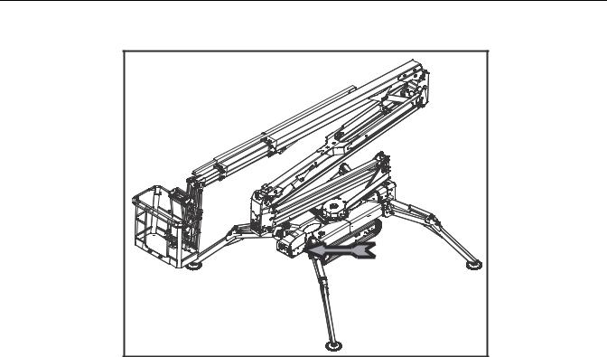
1.7 SERIAL NUMBER LOCATION
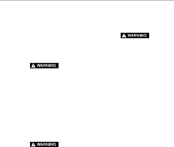
A serial number plate is affixed on to the frame or the basket A frame. The following illustrations showing the position on each model.
Figure 1-1. |
Plate |
Figure 1-2. Plate location on X17J
Figure 1-3. |
Plate location on X14J-X390AJ |
Figure 1-4. |
Plate location on X19J-X550AJ |
3121448 |
– JLG Lift – |
1-11 |
SECTION 1 - SPECIFICATIONS
Figure 1-5. |
Plate location on X23J-X700AJ |
1-12 |
– JLG Lift – |
3121448 |
SECTION 1 - SPECIFICATIONS
 NOTES:
3121448 |
– JLG Lift – |
1-13 |

SECTION 2 - GENERAL
SECTION 2. GENERAL
2.1MACHINE PREPARATION, INSPECTION, AND MAINTENANCE
General
This section provides the necessary information needed by those personnel that are responsible to place the machine in operation readiness and maintain its safe operating condition. For maximum service life and safe operation, ensure that all the necessary inspections and maintenance have been completed before placing the machine into service.
Preparation, Inspection, and Maintenance
It is important to establish and conform to a comprehensive inspection and preventive maintenance program. The following table outlines the periodic machine inspections and maintenance recommended by JLG Industries, Inc. Consult your national, regional, or local regulations for further requirements for aerial work platforms. The frequency of inspections and maintenance must be increased as environment, severity and frequency of usage requires.
Pre-Start Inspection
It is the User’s or Operator’s primary responsibility to perform a Pre-Start Inspection of the machine prior to use daily or at each change of operator. Reference the Operator’s and Safety Manual for completion procedures for the Pre-Start Inspection. The Operator and Safety Manual must be read in its entirety and understood prior to performing the Pre-Start Inspection.
Pre-Delivery Inspection and Frequent Inspection
The Pre-Delivery Inspection and Frequent Inspection shall be performed by a qualified JLG equipment mechanic. JLG Industries, Inc. recognizes a qualified JLG equipment mechanic as a person who, by possession of a recognized degree, certificate, extensive knowledge, training, or experience, has successfully demonstrated the ability and proficiency to service, repair, and maintain the subject JLG product model.
The Pre-Delivery Inspection and Frequent Inspection procedures are performed in the same manner, but at different times. The Pre-Delivery Inspection shall be performed prior to each sale, lease, or rental delivery. The Frequent Inspection shall be accomplished for each machine in service for 3 months or 150 hours (whichever comes first); out of service for a period of more than 3 months; or when purchased used. The frequency of this inspection must be increased as environment, severity and frequency of usage requires.
Reference the JLG Pre-Delivery and Frequent Inspection Form and the Inspection and Preventative Maintenance Schedule for items requiring inspection during the performance of these inspections. Reference the appropriate areas of this manual for servicing and maintenance procedures.
Annual Machine Inspection
The Annual Machine Inspection must be performed by a Factory-Certified Service Technician on an annual basis, no later than thirteen (13) months from the date of the prior Annual Machine Inspection. JLG Industries, Inc. recognizes a Factory-Certified Service Technician as a person who has successfully completed the JLG Service Training School for the subject JLG product model. Reference the machine Service and Maintenance Manual and appropriate JLG inspection form for performance of this inspection.
Reference the JLG Annual Machine Inspection Form and the Inspection and Preventative Maintenance Schedule for items requiring inspection during the performance of this inspection. Reference the appropriate areas of this manual for servicing and maintenance procedures.
For the purpose of receiving safety-related bulletins, it is important that JLG Industries, Inc. has updated ownership information for each machine. When performing each Annual Machine Inspection, notify JLG Industries, Inc. of the current machine ownership.
Preventative Maintenance
In conjunction with the specified inspections, maintenance shall be performed by a qualified JLG equipment mechanic. JLG Industries, Inc. recognizes a qualified JLG equipment mechanic as a person who, by possession of a recognized degree, certificate, extensive knowledge, training, or experience, has successfully demonstrated the ability and proficiency to service, repair, and maintain the subject JLG product model.
Reference the Preventative Maintenance Schedule and the appropriate areas of this manual for servicing and maintenance procedures. The frequency of service and maintenance must be increased as environment, severity and frequency of usage requires.
3121448 |
– JLG Lift – |
2-1 |

SECTION 2 - GENERAL
Table 2-1. Inspection and Maintenance
Type |
Frequency |
Primary |
Service |
Reference |
|
Responsibility |
Qualification |
||||
|
|
|
|||
|
|
|
|
|
|
Pre-Start |
Prior to use each day; or |
User or Operator |
User or Operator |
Operator and Safety Man- |
|
Inspection |
At each Operator change. |
|
|
ual |
|
|
|
|
|
|
|
Pre-Delivery |
Prior to each sale, lease, or |
Owner, Dealer, or |
Qualified JLG |
Service and Maintenance |
|
Inspection |
rental delivery. |
User |
Mechanic |
Manual and applicable JLG |
|
|
|
|
|
inspection form. |
|
|
|
|
|
|
|
Frequent |
In service for 3 months or 150 hours, |
Owner, Dealer, or |
Qualified JLG |
Service and Maintenance |
|
Inspection |
whichever comes first; or |
User |
Mechanic |
Manual and applicable JLG |
|
|
Out of service for a period of more than |
|
|
inspection form. |
|
|
3 months; or |
|
|
|
|
|
Purchased used. |
|
|
|
|
|
|
|
|
|
|
Annual Machine |
Annually, no later than 13 months from |
Owner, Dealer, or |
Factory-Certified |
Service and Maintenance |
|
Inspection |
the date of the prior inspection. |
User |
Service Techni- |
Manual and applicable JLG |
|
|
|
|
cian |
inspection form. |
|
|
|
|
|
|
|
Preventative |
At intervals as specified in the Service |
Owner, Dealer, or |
Qualified JLG |
Service and Maintenance |
|
Maintenance |
and Maintenance Manual. |
User |
Mechanic |
Manual |
|
|
|
|
|
|
2.2 SERVICE AND GUIDELINES
General
The following information is provided to assist you in the use and application of servicing and maintenance procedures contained in this book.
Safety and Workmanship
Your safety, and that of others, is the first consideration when engaging in the maintenance of equipment. Always be conscious of weight. Never attempt to move heavy parts without the aid of a mechanical device. Do not allow heavy objects to rest in an unstable position. When raising a portion of the equipment, ensure that adequate support is provided.
Cleanliness
1.The most important single item in preserving the long service life of a machine is to keep dirt and foreign materials out of the vital components. Precautions have been taken to safeguard against this. Shields, covers, seals, and filters are provided to keep air, fuel, and oil supplies clean; however, these items must be maintained on a scheduled basis in order to function properly.
2.At any time when air, fuel, or oil lines are disconnected, clear adjacent areas as well as the openings and fittings themselves. As soon as a line or component is disconnected, cap or cover all openings to prevent entry of foreign matter.
3.Clean and inspect all parts during servicing or maintenance, and assure that all passages and openings are unobstructed. Cover all parts to keep them clean. Be sure all parts are clean before they are installed. New parts should remain in their containers until they are ready to be used.
Components Removal and Installation
1.Use adjustable lifting devices, whenever possible, if mechanical assistance is required. All slings (chains, cables, etc.) should be parallel to each other and as near perpendicular as possible to top of part being lifted.
2.Should it be necessary to remove a component on an angle, keep in mind that the capacity of an eyebolt or similar bracket lessens, as the angle between the supporting structure and the component becomes less than 90 degrees.
3.If a part resists removal, check to see whether all nuts, bolts, cables, brackets, wiring, etc., have been removed and that no adjacent parts are interfering.
2-2 |
– JLG Lift – |
3121448 |

SECTION 2 - GENERAL
Component Disassembly and Reassembly
When disassembling or reassembling a component, complete the procedural steps in sequence. Do not partially disassemble or assemble one part, then start on another. Always recheck your work to assure that nothing has been overlooked. Do not make any adjustments, other than those recommended, without obtaining proper approval.
Pressure-Fit Parts
When assembling pressure-fit parts, use an anti-seize or molybdenum disulfide base compound to lubricate the mating surface.
Bearings
1.When a bearing is removed, cover it to keep out dirt and abrasives. Clean bearings in nonflammable cleaning solvent and allow to drip dry. Compressed air can be used but do not spin the bearing.
2.Discard bearings if the races and balls (or rollers) are pitted, scored, or burned.
3.If bearing is found to be serviceable, apply a light coat of oil and wrap it in clean (waxed) paper. Do not unwrap reusable or new bearings until they are ready to install.
4.Lubricate new or used serviceable bearings before installation. When pressing a bearing into a retainer or bore, apply pressure to the outer race. If the bearing is to be installed on a shaft, apply pressure to the inner race.
Gaskets
Check that holes in gaskets align with openings in the mating parts. If it becomes necessary to hand-fabricate a gasket, use gasket material or stock of equivalent material and thickness. Be sure to cut holes in the right location, as blank gaskets can cause serious system damage.
Bolt Usage and Torque Application
1.Use bolts of proper length. A bolt which is too long will bottom before the head is tight against its related part. If a bolt is too short, there will not be enough thread area to engage and hold the part properly. When replacing bolts, use only those having the same specifications of the original, or one which is equivalent.
2.Unless specific torque requirements are given within the text, standard torque values should be used on heat-treated bolts, studs, and steel nuts, in accordance with recommended shop practices. (See Torque Chart Section 1.)
Hydraulic Lines and Electrical Wiring
Clearly mark or tag hydraulic lines and electrical wiring, as well as their receptacles, when disconnecting or removing them from the unit. This will assure that they are correctly reinstalled.
Hydraulic System
1.Keep the system clean. If evidence of metal or rubber particles are found in the hydraulic system, drain and flush the entire system.
2.Disassemble and reassemble parts on clean work surface. Clean all metal parts with non-flammable cleaning solvent. Lubricate components, as required, to aid assembly.
Lubrication
Service applicable components with the amount, type, and grade of lubricant recommended in this manual, at the specified intervals. When recommended lubricants are not available, consult your local supplier for an equivalent that meets or exceeds the specifications listed.
Battery
Clean battery, using a non-metallic brush and a solution of baking soda and water. Rinse with clean water. After cleaning, thoroughly dry battery and coat terminals with an anti corrosion compound.
Lubrication and Servicing
Components and assemblies requiring lubrication and servicing are shown in the Lubrication Chart in Section 1.
2.3 LUBRICATION AND INFORMATION
Hydraulic System
1.The primary enemy of a hydraulic system is contamination. Contaminants enter the system by various means, e.g., using inadequate hydraulic oil, allowing moisture, grease, filings, sealing components, sand, etc., to enter when performing maintenance, or by permitting the pump to cavitate due to insufficient system warm-up or leaks in the pump supply (suction) lines.
2.The design and manufacturing tolerances of the component working parts are very close, therefore, even the smallest amount of dirt or foreign matter entering a system can cause wear or damage to the components and generally results in faulty operation. Every precaution must be taken to keep hydraulic oil clean, including reserve oil in storage. Hydraulic system filters should be checked, cleaned, and/or replaced as necessary, at the speci-
3121448 |
– JLG Lift – |
2-3 |

SECTION 2 - GENERAL
fied intervals required in the Lubrication Chart in Section 1. Always examine filters for evidence of metal particles.
3.Cloudy oils indicate a high moisture content which permits organic growth, resulting in oxidation or corrosion. If this condition occurs, the system must be drained, flushed, and refilled with clean oil.
4.It is not advisable to mix oils of different brands or types, as they may not contain the same required additives or be of comparable viscosities. Good grade mineral oils, with viscosities suited to the ambient temperatures in which the machine is operating, are recommended for use.
NOTE: Metal particles may appear in the oil or filters of new machines due to the wear-in of meshing components.
Hydraulic Oil
Refer to Section 1 for recommendations for viscosity ranges.
Changing Hydraulic Oil
1.Filter elements must be changed after the first 50 hours of operation and every 300 hours (unless specified otherwise) thereafter. If it is necessary to change the oil, use only those oils meeting or exceeding the specifications appearing in this manual. If unable to obtain the same type of oil supplied with the machine, consult local supplier for assistance in selecting the proper equivalent. Avoid mixing petroleum and synthetic base oils. JLG Industries recommends changing the hydraulic oil annually.
2.Use every precaution to keep the hydraulic oil clean. If the oil must be poured from the original container into another, be sure to clean all possible contaminants from the service container. Always clean the mesh element of the filter and replace the cartridge any time the system oil is changed.
3.While the unit is shut down, a good preventive maintenance measure is to make a thorough inspection of all hydraulic components, lines, fittings, etc., as well as a functional check of each system, before placing the machine back in service.
Lubrication Specifications
Specified lubricants, as recommended by the component manufacturers, are always the best choice, however, multi-purpose greases usually have the qualities which meet a variety of single purpose grease requirements. Should any question arise, regarding the use of greases in maintenance stock, consult your local supplier for evaluation. Refer to Section 1 for an explanation of the lubricant key designations appearing in the Lubrication Chart.
2.4 CYLINDER DRIFT TEST
Maximum acceptable cylinder drift is to be measured using the following methods.
Cylinder Drift
Table 2-2. Cylinder Drift
Cylinder Bore Diameter |
Max. Acceptable Drift |
|
in 10 Minutes |
||
|
||
|
|
inches |
mm |
inches |
mm |
|
|
|
|
N.A. |
N.A. |
N.A. |
N.A. |
|
|
|
|
N.A. |
N.A. |
N.A. |
N.A. |
|
|
|
|
N.A. |
N.A. |
N.A. |
N.A. |
|
|
|
|
N.A. |
N.A. |
N.A. |
N.A. |
|
|
|
|
N.A. |
N.A. |
N.A. |
N.A. |
|
|
|
|
N.A. |
N.A. |
N.A. |
N.A. |
|
|
|
|
N.A. |
N.A. |
N.A. |
N.A. |
|
|
|
|
N.A. |
N.A. |
N.A. |
N.A. |
Drift is to be measured at the cylinder rod with a calibrated dial indicator. The cylinder oil must be at ambient temperature and temperature stabilized.
The cylinder must have the normal load, which is the normal platform load applied.
If the cylinder passes this test, it is acceptable.
2-4 |
– JLG Lift – |
3121448 |

SECTION 2 - GENERAL
2.5PINS AND COMPOSITE BEARING REPAIR GUIDELINES
Filament wound bearings.
1.Pinned joints should be disassembled and inspected if the following occurs:
a.Excessive sloppiness in joints.
b.Noise originating from the joint during operation.
2.Filament wound bearings should be replaced if any of the following is observed:
a.Frayed or separated fibers on the liner surface.
b.Cracked or damaged liner backing.
c.Bearings that have moved or spun in their housing.
d.Debris embedded in liner surface.
3.Pins should be replaced if any of the following is observed (pin should be properly cleaned prior to inspection):
a.Detectable wear in the bearing area.
b.Flaking, pealing, scoring, or scratches on the pin surface.
c.Rusting of the pin in the bearing area.
4.Re-assembly of pinned joints using filament wound bearings.
a.Housing should be blown out to remove all dirt and debris...bearings and bearing housings must be free of all contamination.
b.Bearing / pins should be cleaned with a solvent to remove all grease and oil...filament wound bearing are a dry joint and should not be lubricated unless otherwise instructed (i.e. sheave pins).
c.Pins should be inspected to ensure it is free of burrs, nicks, and scratches which would damage the bearing during installation and operation.
2.6 WELDING ON JLG EQUIPMENT
NOTE: This instruction applies to repairs, or modifications to the machine and to welding performed from the machine on an external structure, or component,
Do the Following When Welding on JLG Equipment
•Disconnect the battery.
•Disconnect the moment pin connection (where fitted)
•Ground only to structure being welded.
Do NOT Do the Following When Welding on JLG Equipment
•Ground on frame and weld on any other area than the chassis.
•Ground on turntable and weld on any other area than the turntable.
•Ground on the platform/support and weld on any other area than the platform/support.
•Ground on a specific boom section and weld on any other area than that specific boom section.
•Allow pins, wear pads, wire ropes, bearings, gearing, seals, valves, electrical wiring, or hoses to be between the grounding position and the welded area.
FAILURE TO COMPLY WITH THE ABOVE REQUIREMENTS MAY RESULT IN COMPONENT DAMAGE (I.E. ELECTRONIC MODULES, SWING BEARING, COLLECTOR RING, BOOM WIRE ROPES ETC.)
3121448 |
– JLG Lift – |
2-5 |

SECTION 2 - GENERAL
 NOTES:
2-6 |
– JLG Lift – |
3121448 |
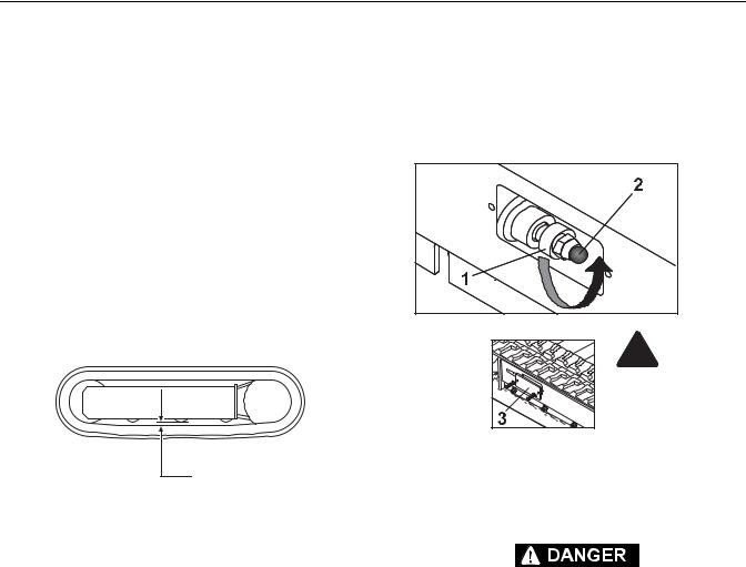
SECTION 3 - CHASSIS & TURNTABLE
SECTION 3. CHASSIS & TURNTABLE
3.1 RUBBER TRACK MAINTENANCE
Checking track tension
Stop the machine on solid, level land. Lift the machine into safe conditions and place stable supports under the undercarriage frame for total support. Parallel with the central roller of the under-carriage, measure distance (A) from the bottom of the roller to the rigid inside of the rubber belt. Track tension is normal if measurement (A) is between 10 and 15 mm.
If track tension is not within the measurements specified above, loose or too taught, follow the procedures illustrated in the paragraph below.
A
Figure 3-1.
Operations for loosening/tightening the track
The grease contained in the hydraulic track is pressurised. For this reason, do not loosen the greasing valve (1) by more than 1 turn; if the valve is loosened too much, it risks being expelled under the effect of the pressure of the grease, putting the safety of the operator at risk. Never loosen greaser (2).
When gravel or mud are blocked between the toothed wheel and the track links, remove it before loosening.
1.Remove the screws and take of adjustment access lid 3.
2.To loosen the track, slowly unscrew valve 1 in an anti-clockwise direction for no more than one turn. One turn of valve 1 is sufficient to loosen the track.
3.If the grease does not start to drain, turn the track slowly.
4.When correct track tension has been obtained, turn valve (1) in a clockwise direction and tighten it. Clean all traces of grease.
 DANGER
Figure 3-2.
5.To tighten the track, connect a grease gun to greaser (2) and add grease until belt tension is within the specified values.
IT IS NOT NORMAL IF THE TRACK REMAINS TAUGHT AFTER HAVING TURNED VALVE (1) IN AN ANTI-CLOCKWISE DIRECTION OR IF THE TRACK IS STILL LOOSE AFTER HAVING PUT GREASE INTO GREASER (2). NEVER TRY TO REMOVE THE TRACKS OR DISASSEMBLE THE TRACK-TENSIONER CYLINDER BECAUSE THE GREASE PRESSURE INSIDE THE TRACK IS VERY DANGEROUS.
3121448 |
– JLG Lift – |
3-1 |
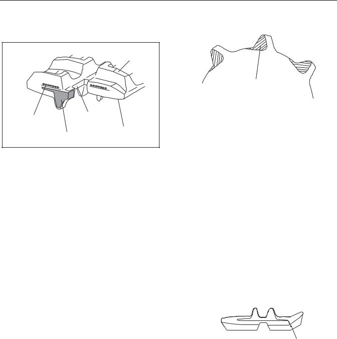
SECTION 3 - CHASSIS & TURNTABLE
Checking The Rubber Tracks
PATTERN
STEEL WIRE |
SPROCKET |
HOLE |
WHEEL SIDE
METAL CORE
Figure 3-3. Rubber Track Structure
The structure of the rubber track is illustrated in Figure 3-3. The steel ropes and the metal core are sunk into the rubber. The carved profiles are used to give stability when moving over loose land. They are situated in the lower part resting on the ground, while the wheel guides situated inside the track, prevent the track from escaping from the guide rollers.
CAUSES OF DAMAGE
1.Breakage of the steel ropes
Excessive tension causes the steel ropes to break in the following conditions:
a.when stones or foreign bodies accumulate between the track and the under-carriage frame;
b.when the track escapes from its guide;
c.in the case of strong friction such as rapid direction changes.
2.Wear and breakage of the metal cores
As for breakage of the steel ropes, stated above, excessive tension may cause the metal cores to bend or break, as may the following causes:
a.incorrect contact between toothed wheel and track;
b.breakage of internal rollers;
c.functioning on sandy land.
3. Separation of the metal cores
WORN PARTS
Figure 3-4.
a.The metal core acts as a type of adhesive of the rubber between the core itself and the steel ropes. Separation may be caused by excessive tension as breakage of the ropes for the following reasons:
b.The metal cores have been wound by the worn toothed wheel as indicated in the figure. When this wear and abrasion is detected, the toothed wheel must be replaced as soon as possible.
c.If it breaks, as stated in item 2, "Wear and breakage of the metal cores", the track must be replaced because this damage leads to a complete loss of functions.
4.Abrasion and fatigue cracks
a.The cracks at the base of the carved profile occur due to bending fatigue of the rubber caused by the toothed wheel and the tracktensioning wheel.
b.The cracks and bends on the edge of the rubber are due to manoeuvres with the track in presence of cement kerbs and edges.
CRACK
Figure 3-5.
c.The cracks and abrasions in the rubber on the tracks of the roller guide originate from fatigue from the compression of the rubber by the weight of the wheel, together with functioning on sandy land, or repeated and abrupt changes of direction.
d.Abrasion of the carved profiles may occur especially if slewing on concrete surfaces or on gravel or hard surfaces are carried out.
e.The damage indicated in paragraphs a, b, and c above, must not be considered fatal for the track and, even if in presence of gradual
3-2 |
– JLG Lift – |
3121448 |
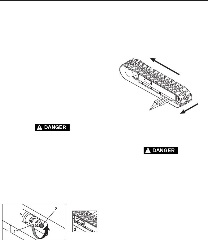
SECTION 3 - CHASSIS & TURNTABLE
and progressive damage, they allow the track to continue working. The development of the damage indicated in point 3 leads to the exposure of the metal cores and if they are exposed for more than half of the track circumference, it means that it is time to replace them. It can however still be used.
5.Cracks due to external factors
Cracks on external track surfaces (those in contact with the ground) are often due to contact with gravel, sharp stones, sharp materials, nails, glass, which cause cuts. From the rubber properties point of view, this is inevitable although it does depend on service conditions. Cracks on the internal surface of the circumference and on the edge of the rubber originate from contact of the belt with the structure of the undercarriage or with sharp concrete edges. The increase in cracks is relatively small. Even if it does not appear to be in good condition the track can be used in heavy duty conditions.
Replacing The Rubber Tracks
THE GREASE CONTAINED IN THE HYDRAULIC TRACK IS PRESSURISED. FOR THIS REASON, DO NOT LOOSEN THE GREASING VALVE (1) BY MORE THAN 1 TURN; IF THE VALVE IS LOOSENED TOO MUCH, IT RISKS BEING EXPELLED UNDER THE EFFECT OF THE PRESSURE OF THE GREASE, PUTTING THE SAFETY OF THE OPERATOR AT RISK. NEVER LOOSEN GREASER (2).
When gravel or mud are blocked between the toothed wheel and the track links, remove it before loosening.
Removing The Rubber Track
1.Stop the machine on solid, level land, lift it and support it in safe conditions, using the outriggers.
Figure 3-6. |
2.Remove the screws and take of adjustment access lid 3.
3.To loosen the track, slowly unscrew valve 1 in an anti-clockwise direction for no more than one turn. One turn of valve 1 is sufficient to loosen the track.
4.If the grease does not start to drain, turn the track slowly.
5.Insert three steel pipes (4) inside the track in the space between the rollers. Turn the driving wheel backwards (5) in a way that the steel pipes proceed with the track and engage on the track-tensioning wheel. Apply force (6) laterally to allow the track to run and lift it from the track-tensioning wheel.
5
520202BH19
4
6
Figure 3-7.
Installing The Rubber Track
ENSURE SAFE CONDITIONS WITH THE MACHINE LIFTED TO PROCEED WITH MOUNTING THE TRACKS.
1.Check that the grease contained in the hydraulic cylinder has been removed.
2.Engage the track links with the toothed wheel and position the other end of the track on the track-ten- sioning wheel.
3.Turn the driving wheel in reverse (7) pushing the track plate inside the frame (8).
4.Position the track using a steel pipe and turn the driving wheel again.
5.Ensure that the track links are correctly engaged in the toothed wheel and in the track-tensioning wheel.
6.Adjust track tension (see paragraph -Operations for loosening/tightening the track).
7.Rest the tracked under-carriage on the ground.
3121448 |
– JLG Lift – |
3-3 |
 Loading...