

Page 1

Illustrated Parts Manual
Models
1532E2
1932E2
2032E2
2632E2
2646E2
3246E2
3120738
September 24, 2013
Page 2

Page 3

REVISION LOG
February 1998 - Original Issue Of Manual (Edited to 0010549 Revision 3)
July 1998 - Revised Manual (Edited to 0010549 Revision 10)
February 26, 1999 - Revised Manual (Edited to 0010549 Revision 18)
May 1, 1999 - Revised Manual (Edited to 0010549 Revision 21)
August 30, 1999 - Revised Manual (Edited to 0010549 Revision 24)
January 1, 2000 - Revised Manual (Edited to 0010549 Revision 31)
June 15, 2000 - Revised Manual (Edited to 0010549 Revision 33)
October 31, 2000 - Revised Manual (Edited to 0010549 Revision 35)
January 30, 2001 - Revised Manual (Edited to 0010549 Revision 40)
July 2, 2001 - Revised Manual (Edited to 0010549 Revision 45)
October 29, 2001 - Revised Manual (Edited to 0010549 Revision 49)
May 23, 2002 - Revised Manual (Edited to 0010549 Revision 57)
September 20, 2002 - Revised Manual (Edited to 0010549 Revision 61)
February 26, 2003 - Revised Manual (Edited to 0010549 Revision 65)
June 26, 2003 - Revised Manual (Edited to 0010549 Revision 70)
June 29, 2004 - Revised Manual (Edited to 0010549 Revision 73)
April 7, 2005 - Revised Manual (Edited to 0010549 Revision 73)
September 9, 2008 - Revised Manual
November 30, 2011 - Revised Manual
September 24, 2013 - Revised Manual
3120738 A
Page 4

REVISION LOG
B 3120738
Page 5

TABLE OF CONTENTS
FIGURE NO. TITLE PAGE NO.
SECTION 1 - FRAME . . . . . . . . . . . . . . . . . . . . . . . . . . . . . . . . . . . . . . . . . . . . . . . . . . . . . .1-1
1-1 WHEEL DRIVE AND STEERING INSTALLATION - 1532E2 & 1932E2 . . . . . . . . . . . . . .1-2
1-2 DRIVE MOTOR ASSEMBLY - 1532E2 & 1932E2
1-3 BRAKE INSTALLATION - 1532E2 & 1932E2 . . . . . . . . . . . . . . . . . . . . . . . . . . . . . . . . .1-8
1-4 FRAME AND STEERING INSTALLATION - 2032E2/2632E2/2646E2/3246E2 . . . . . . . .1-10
1-5 WHEEL DRIVE AND BRAKE INSTALLATIONS - 2032E2/2632E2/2646E2/3246E2 . . . .1-14
1-6 DRIVE MOTOR ASSEMBLY - (2032E2/2646E2 S/N 90870 to Present)
(2632E2/3246E2 S/N 90855 to Present). . . . . . . . . . . . . . . . . . . . . . . . . . . . . . . . . . . .1-18
1-7 FRAME MOUNTED COMPONENTS INSTALLATIONS . . . . . . . . . . . . . . . . . . . . . . . . . .1-22
SECTION 2 - GROUND CONTROLS . . . . . . . . . . . . . . . . . . . . . . . . . . . . . . . . . . . . . . . . . .2-1
2-1 HYDRAULIC COMPONENTS INSTALLATIONS - 1532E2/1932E2 . . . . . . . . . . . . . . . .2-2
2-2 HYDRAULIC COMPONENTS INSTALLATIONS - 2032E2/2632E2/2646E2/3246E2 . . .2-6
2-3 VALVE ASSEMBLY - STANDARD CONTROLS MACHINES . . . . . . . . . . . . . . . . . . . . . .2-10
2-4 VALVE ASSEMBLY - PROPORTIONAL CONTROLS MACHINES. . . . . . . . . . . . . . . . . .2-14
2-5 ELECTRICAL COMPONENTS INSTALLATION (LEFT SIDE OF MACHINES WITH
STANDARD CONTROLS) . . . . . . . . . . . . . . . . . . . . . . . . . . . . . . . . . . . . . . . . . . . . . . . .2-18
2-6 ELECTRICAL COMPONENTS INSTALLATION (LEFT SIDE OF MACHINES WITH
PROPORTIONAL CONTROLS) . . . . . . . . . . . . . . . . . . . . . . . . . . . . . . . . . . . . . . . . . . . .2-22
2-7 ELECTRICAL COMPONENTS INSTALLATION (RIGHT SIDE) . . . . . . . . . . . . . . . . . . . .2-26
2-8 BATTERY CHARGER ASSEMBLIES . . . . . . . . . . . . . . . . . . . . . . . . . . . . . . . . . . . . . . . .2-30
2-9 POTHOLE PROTECTION AND TRAY INSTALLATIONS . . . . . . . . . . . . . . . . . . . . . . . . .2-34
(S/N 90870 to Present) . . . . . . . . . . . . .1-6
SECTION 3 - SIZZOR ARMS . . . . . . . . . . . . . . . . . . . . . . . . . . . . . . . . . . . . . . . . . . . . . . . .3-1
3-1 SCISSOR ARMS INSTALLATION - 1532E2 . . . . . . . . . . . . . . . . . . . . . . . . . . . . . . . . . . .3-2
3-2 SCISSOR ARMS INSTALLATION - 1932E2 . . . . . . . . . . . . . . . . . . . . . . . . . . . . . . . . . . .3-6
3-3 SCISSOR ARMS INSTALLATION - 2032E2 . . . . . . . . . . . . . . . . . . . . . . . . . . . . . . . . . .3-10
3-4 SCISSOR ARMS INSTALLATION - 2632E2 . . . . . . . . . . . . . . . . . . . . . . . . . . . . . . . . . .3-14
3-5 SCISSOR ARMS INSTALLATION - 2646E2 . . . . . . . . . . . . . . . . . . . . . . . . . . . . . . . . . . .3-18
3-6 SCISSOR ARMS INSTALLATION - 3246E2 . . . . . . . . . . . . . . . . . . . . . . . . . . . . . . . . . . .3-22
SECTION 4 - PLATFORM. . . . . . . . . . . . . . . . . . . . . . . . . . . . . . . . . . . . . . . . . . . . . . . . . . .4-1
4-1 PLATFORM AND ACCESSORIES INSTALLATION . . . . . . . . . . . . . . . . . . . . . . . . . . . .4-2
4-2 STANDARD HANDRAILS INSTALLATION (1532E2/1932E2) . . . . . . . . . . . . . . . . . . . . .4-6
4-3 FOLDDOWN HANDRAILS INSTALLATION (1532E2/1932E2) . . . . . . . . . . . . . . . . . . . .4-10
4-4 STANDARD HANDRAILS INSTALLATION (2032E2) . . . . . . . . . . . . . . . . . . . . . . . . . . .4-14
4-5 FOLDDOWN HANDRAILS INSTALLATION (2032E2/2632E2) . . . . . . . . . . . . . . . . . . . .4-18
4-6 FOLDDOWN HANDRAILS INSTALLATION (2632E2) . . . . . . . . . . . . . . . . . . . . . . . . . . .4-22
4-7 FOLDDOWN HANDRAILS INSTALLATION (2646E2/3246E2) . . . . . . . . . . . . . . . . . . . .4-26
4-8 PLATFORM CONSOLE BOX ASSEMBLIES (STANDARD CONTROLS MACHINES). . .4-30
4-9 PLATFORM CONSOLE BOX ASSEMBLIES (PROPORTIONAL CONTROLS
MACHINES) . . . . . . . . . . . . . . . . . . . . . . . . . . . . . . . . . . . . . . . . . . . . . . . . . . . . . . . . 4-34
4-10 CONTROLLER ASSEMBLY (STANDARD CONTROLS MACHINES) . . . . . . . . . . . . . . .4-38
4-11 CONTROLLER ASSEMBLY (PROPORTIONAL CONTROLS MACHINES) . . . . . . . . . . .4-40
3120738 i
Page 6

TABLE OF CONTENTS
FIGURE NO. TITLE PAGE NO.
SECTION 5 - CYLINDER . . . . . . . . . . . . . . . . . . . . . . . . . . . . . . . . . . . . . . . . . . . . . . . . . . . 5-1
5-1 BRAKE CYLINDER ASSEMBLY. . . . . . . . . . . . . . . . . . . . . . . . . . . . . . . . . . . . . . . . . . . .5-2
5-2 LIFT CYLINDER COMPONENTS ASSEMBLY (1532E2 & 1932E2) . . . . . . . . . . . . . . . .5-4
5-3 LIFT CYLINDER COMPONENTS ASSEMBLY (2032E2) . . . . . . . . . . . . . . . . . . . . . . . . .5-8
5-4 LIFT CYLINDER COMPONENTS ASSEMBLY (2646E2) . . . . . . . . . . . . . . . . . . . . . . . . 5-12
5-5 LIFT CYLINDER COMPONENTS ASSEMBLY (3246E2) . . . . . . . . . . . . . . . . . . . . . . . . 5-16
5-6 STEER CYLINDER ASSEMBLY . . . . . . . . . . . . . . . . . . . . . . . . . . . . . . . . . . . . . . . . . . .5-20
SECTION 6 - HYDRAULIC . . . . . . . . . . . . . . . . . . . . . . . . . . . . . . . . . . . . . . . . . . . . . . . . . . 6-1
6-1 HYDRAULIC DIAGRAM - 1532E2 & 1932E2 & 2032E2 . . . . . . . . . . . . . . . . . . . . . . . . .6-2
6-2 HYDRAULIC DIAGRAM - 2646E2 . . . . . . . . . . . . . . . . . . . . . . . . . . . . . . . . . . . . . . . . . .6-6
6-3 HYDRAULIC DIAGRAM - 3246E2 WITH STANDARD CONTROLS . . . . . . . . . . . . . . . . . 6-8
6-4 HYDRAULIC DIAGRAM - 3246E2 WITH PROPORTIONAL CONTROLS. . . . . . . . . . . . . 6-10
6-5 HYDRAULIC DIAGRAM - 2632E2 WITH STANDARD CONTROLS . . . . . . . . . . . . . . . . . 6-12
6-6 HYDRAULIC DIAGRAM - 2632E2 WITH PROPORTIONAL CONTROLS. . . . . . . . . . . . . 6-14
6-7 HYDRAULIC DIAGRAM LIST . . . . . . . . . . . . . . . . . . . . . . . . . . . . . . . . . . . . . . . . . . . . . .6-16
SECTION 7 - ELECTRICAL . . . . . . . . . . . . . . . . . . . . . . . . . . . . . . . . . . . . . . . . . . . . . . . . . 7-1
7-1 ELECTRICAL SCHEMATIC (STANDARD CONTROLS MACHINES). . . . . . . . . . . . . . . .7-2
7-2 ELECTRICAL SCHEMATIC (PROPORTIONAL CONTROLS MACHINES) . . . . . . . . . . .7-4
7-3 ELECTRICAL COMPONENTS INSTALLATION (STANDARD CONTROLS MACHINES) 7-6
7-4 ELECTRICAL COMPONENTS INSTALLATION (PROPORTIONAL CONTROLS
MACHINE) . . . . . . . . . . . . . . . . . . . . . . . . . . . . . . . . . . . . . . . . . . . . . . . . . . . . . . . . . .7-12
7-5 ELECTRICAL DIAGRAM LIST . . . . . . . . . . . . . . . . . . . . . . . . . . . . . . . . . . . . . . . . . . . . .7-18
SECTION 8 - DECALS . . . . . . . . . . . . . . . . . . . . . . . . . . . . . . . . . . . . . . . . . . . . . . . . . . . . . 8-1
8-1 DECALS INSTALLATION - 1532E2 & 1932E2 (COMMON) . . . . . . . . . . . . . . . . . . . . . .8-2
8-2 DECALS INSTALLATION - 1532E2 & 1932E2 (COUNTRY SPEC) . . . . . . . . . . . . . . . . .8-6
8-3 DECALS INSTALLATION - 2032E2 & 2632E2 & 2646E2 & 3246E2 (COMMON) . . . . . 8-12
8-4 DECALS INSTALLATION - 2032E2 & 2632E2 & 2646E2 & 3246E2 (COUNTRY SPEC)8-16
SECTION 9 - RECOMMENDED SERVICE PARTS STOCK . . . . . . . . . . . . . . . . . . . . . . . . 9-1
SECTION 10 - SPECIAL OPTIONS . . . . . . . . . . . . . . . . . . . . . . . . . . . . . . . . . . . . . . . . . . . 10-1
SECTION 11 - INDEX . . . . . . . . . . . . . . . . . . . . . . . . . . . . . . . . . . . . . . . . . . . . . . . . . . . . . . 11-1
ii 3120738
Page 7

SECTION 1 FRAME
S
TABLE OF CONTENTS
FIGURE DESCRIPTION PAGE
1-1 Wheel Drive And Steering Installation - 1532E2 & 1932E2 . . . . . . . . . . . . . . . . . . . . . . . . . . . . 1-2
1-2 Drive Motor Assembly - 1532E2 & 1932E2 (S/N 90870 to Present) . . . . . . . . . . . . . . . . . . . . . 1-6
1-3 Brake Installation - 1532E2 & 1932E2 . . . . . . . . . . . . . . . . . . . . . . . . . . . . . . . . . . . . . . . . . . . . 1-8
1-4 Frame And Steering Installation - 2032E2/2632E2/2646E2/3246E2 . . . . . . . . . . . . . . . . . . . . . 1-10
1-5 Wheel Drive And Brake Installations - 2032E2/2632E2/2646E2/3246E2 . . . . . . . . . . . . . . . . . 1-14
1-6 Drive Motor Assembly - (2032E2/2646E2 S/N 90870 to Present) (2632E2/3246E2
S/N 90855 to Present) . . . . . . . . . . . . . . . . . . . . . . . . . . . . . . . . . . . . . . . . . . . . . . . . . . . . . . 1-18
1-7 Frame Mounted Components Installations . . . . . . . . . . . . . . . . . . . . . . . . . . . . . . . . . . . . . . . . 1-22
E
C
T
I
O
N
1
F
R
A
M
E
3120738 1-1
Page 8
SECTION 1 FRAME
9
22
7
23
16
18
102A
102
105
201
104
107
101
108
103
106
109
3
5
25
17
6
10
4
19
8
11
212020121213141515
2
1
1
110
S
E
C
T
I
O
N
1
F
R
A
M
E
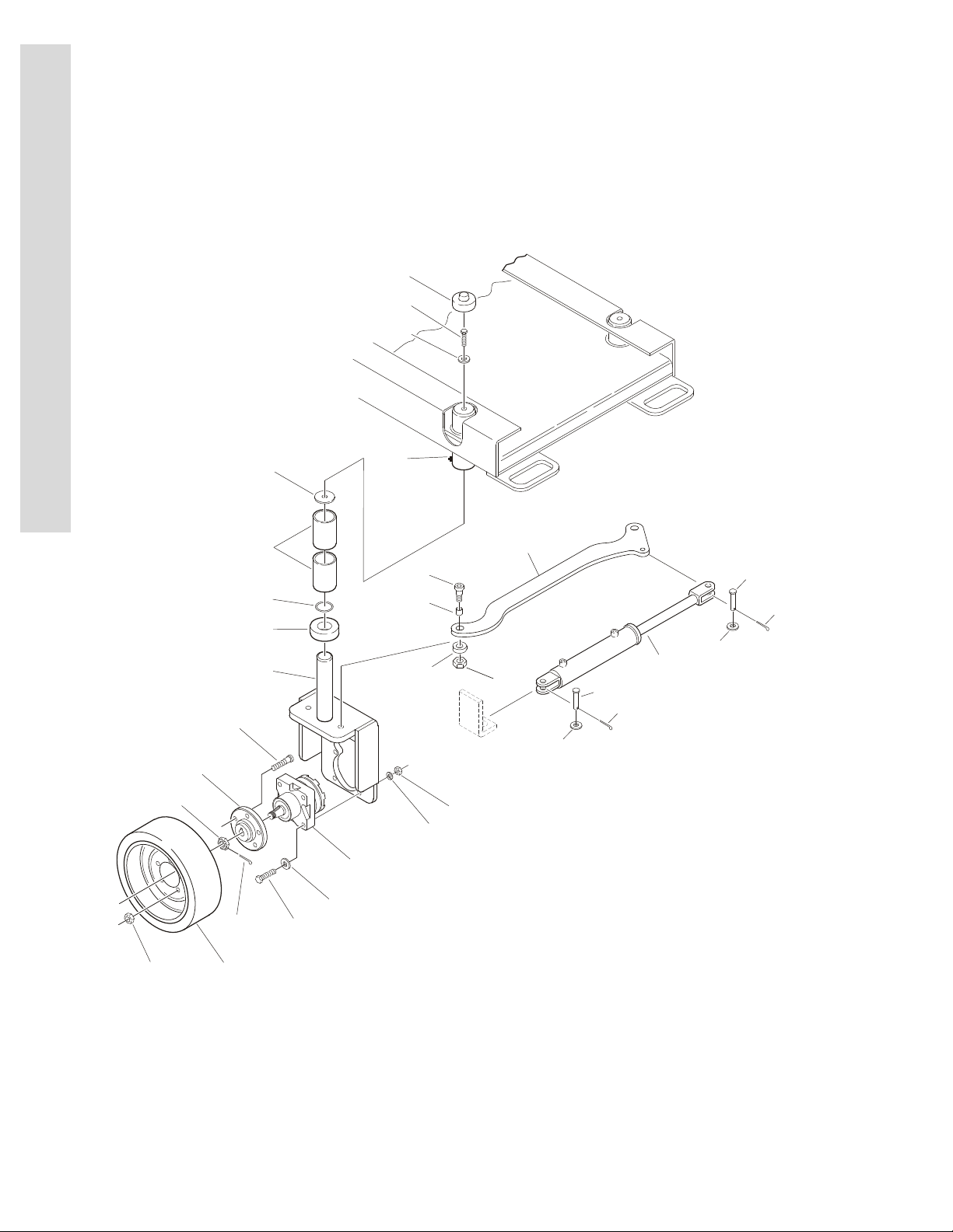
FIGURE 1-1. WHEEL DRIVE AND STEERING INSTALLATION - 1532E2 & 1932E2
1-2 3120738
Page 9

SECTION 1 FRAME
.
FIGURE 1-1. WHEEL DRIVE AND STEERING INSTALLATION - 1532E2 & 1932E2
FIG & ITEM # PART NUMBER DESCRIPTION QTY. REV.
0258015 STEERING INSTALLATION Ref. J
1 0100019 Loctite #271 A/R
2 0100081 Loctite #454 A/R
3 0630516 Bolt, Shoulder 2
4 0641611 Bolt 3/8”-16NC x 1 3/8” 2
5 0962208 Spacer, Bushing 2
6 0962173 Bushing 2
7 0962174 Bushing 4
8 1120064 Cap, Grease Fitting (Prior to S/N 84437) 2
9 1120515 Cap, Plastic 2
10 Steer Cylinder Assembly (See Section 5 for Breakdown) 1
Use 1684225 Prior to S/N 67287 (Was P/N 1683661)
S/N 67287 to S/N 108168 (Was P/N 1683832)
1684225 S/N 108168 to Present
11 2160006 Fitting, Grease (Prior to S/N 84437) 2
12 3430811 Pin, Clevis A/R
13 3431014 Pin, Clevis (Prior to S/N 50027) 1
14 3450404 Pin, Cotter 1/8” x 1” (Prior to S/N 50027) 1
15 3450406 Pin, Cotter 1/8” x 1 1/2” A/R
16 3790218 O-Ring (Prior to S/N 101149) 2
17 3841378 Tie-Rod 1
18 4130356 Spindle 2
19 4711600 Flatwasher 3/8” Narrow 2
20 4711800 Flatwasher 1/2” Narrow A/R
21 4712000 Flatwasher 5/8” Narrow (Prior to S/N 50027) 2
22 4740419 Thrustwasher 2
23 Collar: 2
Use 1440329 Prior to S/N 99064(1932E2)/
Prior to June 13, 2001(1532E2)(Was P/N 1440326)
1440329 S/N 99064 to Present (1932E2)/
June 13, 2001to Present (1532E2)
24 3020025 Grease (Not Shown) (Prior to S/N 108196) A/R
25 3312002 Jam Nut (S/N 103651 to Present) 2
S
E
C
T
I
O
N
1
F
R
A
M
E
WHEEL DRIVE INSTALLATION OPTIONS: Ref.
0258171 (Prior to S/N 90870) Ref. F
0271221 (S/N 90870 to Present) Ref. A
101 Bolt Options: 8
0641824 Bolt 1/2”-13NC x 3” (Prior to S/N 49303)
0681822 Bolt 1/2”-13NC x 2 3/4” (S/N 49303 to Present)
102 2780216 Hub Assembly 2
102A 7012613 Bolt, Wheel (5 Per Hub) 10
103 Drive Motor Assembly Options: 2
3160229 (Prior to S/N 90870)
7018996 Key, Shaft 1
7018997 Nut, Castle 1
3120738 1-3
Page 10

SECTION 1 FRAME
S
E
C
T
I
O
N
1
F
R
A
M
E
FIGURE 1-1. WHEEL DRIVE AND STEERING INSTALLATION - 1532E2 & 1932E2 (CONTINUED)
FIG & ITEM # PART NUMBER DESCRIPTION QTY. REV.
103 (cont’d) 7021312 Seal, Shaft Oil (Inner Seal) 1
7021317 Seal, Dust (Outer Seal) 1
3160269 (S/N 90870 to Present) (See Figure 1-2 for Breakdown)
104 3300255 Nut, Wheel 10
105 See Note Nut (Note: See Breakdown of Individual Motor) 2
106 Hardware Options: 8
3271805 Locknut 1/2”-13NC (Grade 8) (Prior to S/N 49303)
3311801 Nut 1/2”-13NC (S/N 49303 to S/N 84080)
3300450 Nut 1/2”-13NC (S/N 84080 to Present)
107 3450406 Pin, Cotter 1/8” x 1 1/2” 2
108 Use 4740453 Flatwasher 1/2” Narrow
(Was P/N 4891800 Prior to S/N 90870)
109 4761800 Lockwasher 1/2” (S/N 49303 to S/N 84080) 8
110 0100019 Loctite #271 (Prior to S/N 84080) A/R
TIRE AND WHEEL INSTALLATIONS Ref.
0258167 Black Tire and Wheel Installation Ref. 1
0258166 Gray Non-Marking Tire and Wheel Installation Ref. 1
201 Tire Options: 4
4860180 Standard Black A/R
4860182 Non-Marking Gray A/R
8
FRAME OPTIONS 1
2360459 ANSI Machines (Prior to S/N 50363)
2360482 ANSI Machines (S/N 50363 to Present)
2360482 CSA Spec Machines
1-4 3120738
Page 11

SECTION 1 FRAME
FIGURE 1-1. WHEEL DRIVE AND STEERING INSTALLATION - 1532E2 & 1932E2 (CONTINUED)
FIG & ITEM # PART NUMBER DESCRIPTION QTY. REV.
S
E
C
T
I
O
N
1
F
R
A
M
E
3120738 1-5
Page 12
SECTION 1 FRAME
S
E
C
T
I
O
N
1
F
R
A
M
E
FIGURE 1-2. DRIVE MOTOR ASSEMBLY - 1532E2 & 1932E2 (S/N 90870 TO PRESENT)
1-6 3120738
Page 13

SECTION 1 FRAME
.
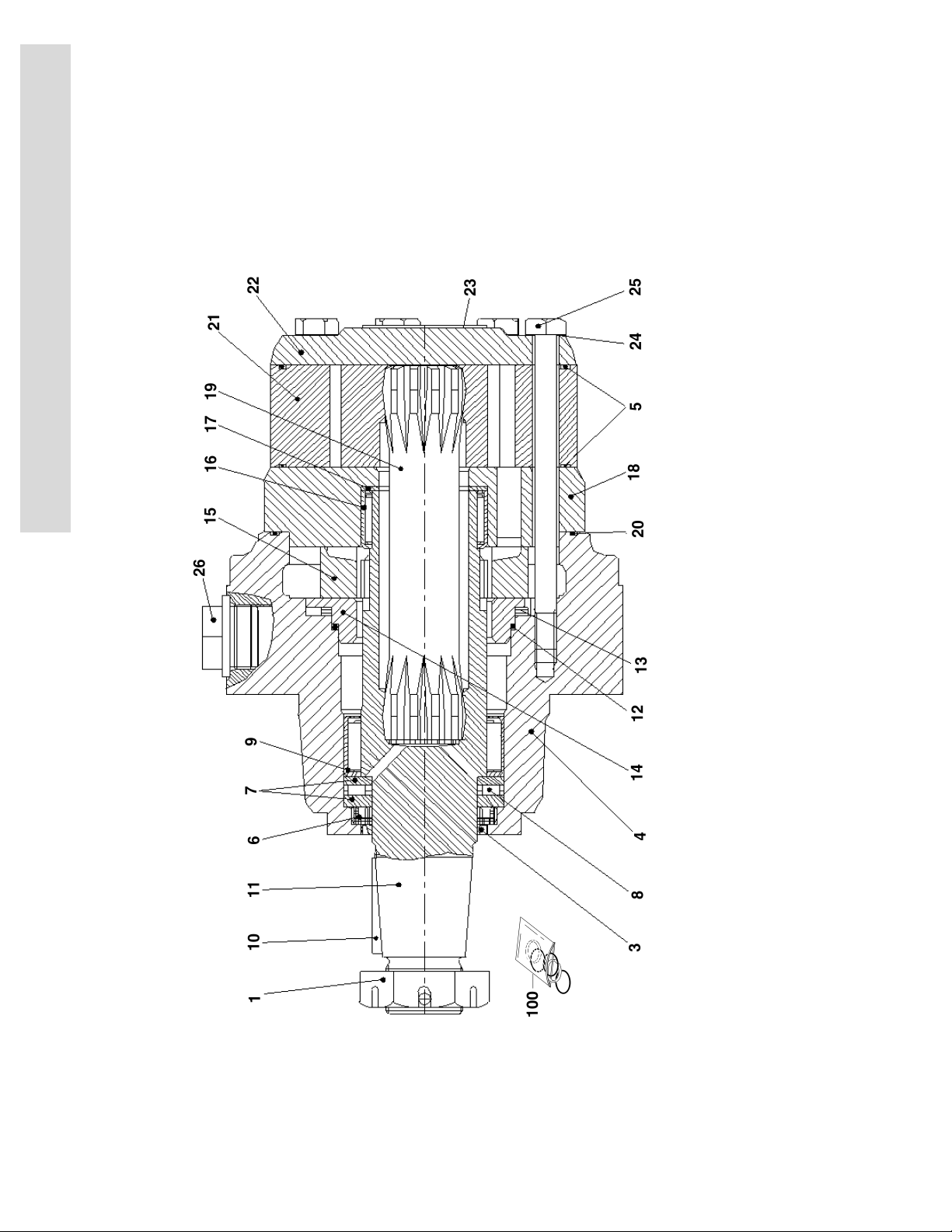
FIGURE 1-2. DRIVE MOTOR ASSEMBLY - 1532E2 & 1932E2 (S/N 90870 TO PRESENT)
FIG & ITEM # PART NUMBER DESCRIPTION QTY. REV.
3160269 DRIVE MOTOR ASSEMBLY Ref. B
1 7023451 Nut, Castle 1
2 Not Used
3 Use Item 100 Seal, Dust 1
4 Not Serviceable Housing
5 Use Item 100 O-Ring 1
6 Use Item 100 Seal, Shaft 1
7 7023452 Bearing, Race 2
8 7023453 Bearing, Needle 1
9 7023454 Bearing, Needle 1
10 7023455 Key 1
11 7023456 Shaft, Output 1
12 Use Item 100 O-Ring 1
13 7023457 Washer, Spring 1
14 7023458 Plate, Pressure 1
15 7023459 Disc, Valve 1
16 7023460 Bearing, Needle 1
17 7023461 Washer, Glacier 1
18 7023462 Plate 1
19 7023463 Shaft, Cardan 1
20 Use Item 100 O-Ring 2
21 7023464 Wheel, Gear Set 1
22 7023465 Cover, End 1
23 Not Serviceable I.D. Tag 1
24 Use Item 100 Washer 7
25 7023466 Screw 7
26 Not Serviceable Plug 2
S
E
C
T
I
O
N
1
F
R
A
M
E
KIT OPTIONS: Ref.
100 7023450 Kit, Seal (Includes Items 3, 5-6, 12, 20, 24) 1
3120738 1-7
Page 14
SECTION 1 FRAME
201
1
5
10
12
14
11
13
16
6
8
9
715109110
3
112
11
11022
113
103
101
410
8
S
E
C
T
I
O
N
1
F
R
A
M
E
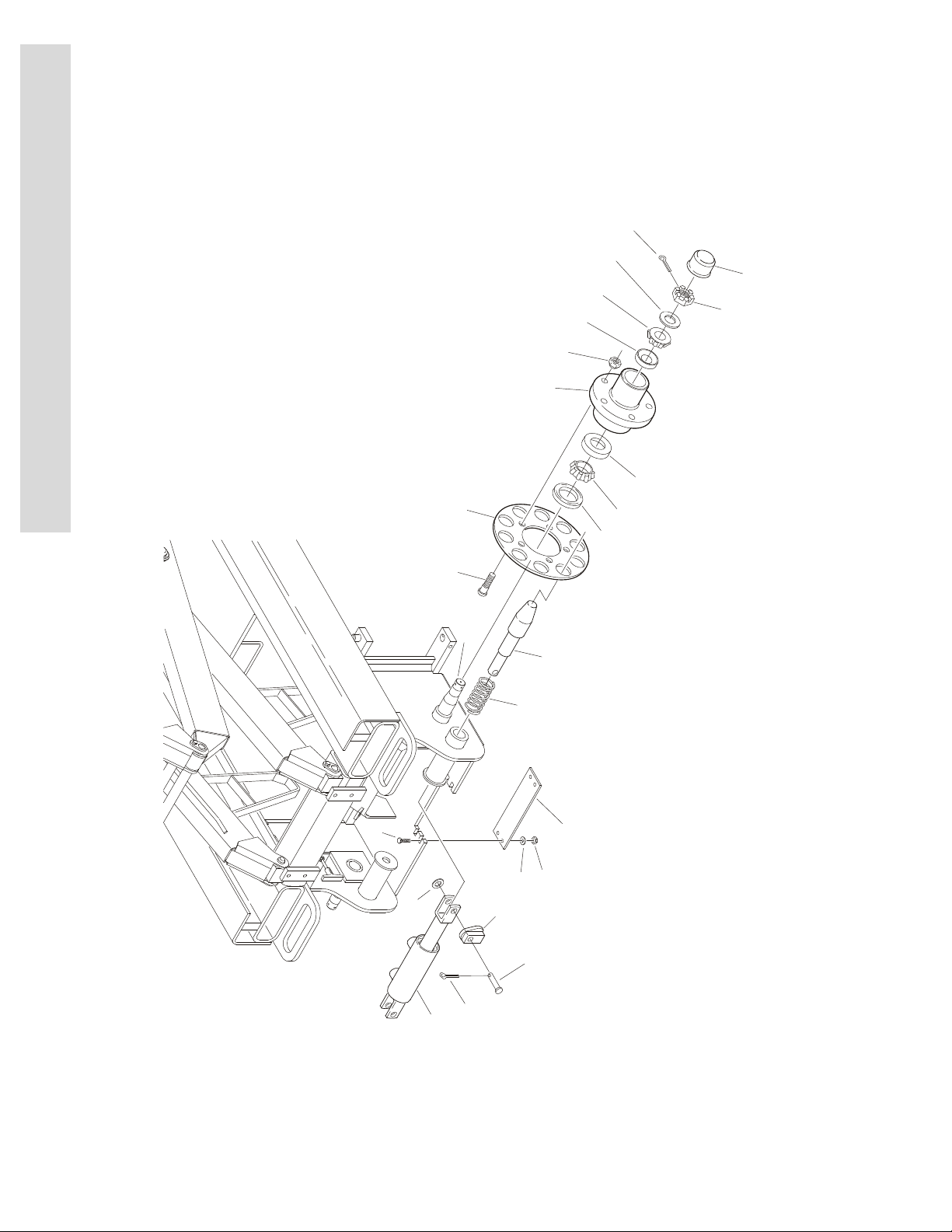
FIGURE 1-3. BRAKE INSTALLATION - 1532E2 & 1932E2
1-8 3120738
Page 15

SECTION 1 FRAME
FIGURE 1-3. BRAKE INSTALLATION - 1532E2 & 1932E2
S
E
FIG & ITEM # PART NUMBER DESCRIPTION QTY. REV.
BRAKE INSTALLATION OPTIONS: Ref.
0258168 1532E2 & 1932E2 Machines Ref. C
1 Brake Cylinder Assembly Options
(See Section 5 for Breakdown):
Use 1683833 Prior to S/N 65498 (Was p/n 1683557)
1683833 S/N 65498 to Present
2 2780215 Hub Assembly (See Items 101-113 for Breakdown) 2
3 3300255 Nut, Wheel 10
4 3300423 Nut 2
5 3430620 Pin 2
6 3450403 Pin, Cotter 1/8” x 3/4” 2
7 3450406 Pin, Cotter 1/8” x 1 1/2” 2
8 3841332 Rod 2
9 4160137 Spring, Compression 2
10 4845037 Brake Cam Weldment 2
11 0641407 Bolt 1/4”-20NC x 7/8” 4
12 3311405 Locknut 1/4”-20NC 4
13 3571067 Plate, Cover 1
14 4711400 Flatwasher 1/4” Narrow 8
15 4740468 Washer, Special 2
16 4711600 Flatwasher 3/8” Narrow 2
1
C
T
I
O
N
1
F
R
A
M
E
2780215 HUB ASSEMBLY Ref. B
101 7010649 Seal 1
102 Not Serviced Housing 1
103 7019696 Stud, Wheel 5
104 to 107 Not Used
108 7010648 Cap, Dust 1
109 7010646 Cone, Outer 1
110 7010650 Cup, Outer 1
111 7010651 Cup, Inner 1
112 7010647 Cone, Inner 1
113 1760165 Disc, Brake 1
FRAME COMPONENTS Ref.
201 4845628 Spindle 2
TIRE AND WHEEL INSTALLATIONS (NOT SHOWN) Ref.
0258167 Black Tire and Wheel Installation Ref. 1
0258166 Gray Non-Marking Tire and Wheel Installation Ref. 1
Tire Options: 4
4860180 Standard Black A/R
4860182 Non-Marking Gray A/R
3120738 1-9
Page 16

SECTION 1 FRAME
300
200
7
19
17
12
22
111
112
101
19
3
3
108
9
24
109
110
23
103
15
1
5
11
11
10
13
21
14
16
6
18
8
10
4
20
5
2
7
S
E
C
T
I
O
N
1
F
R
A
M
E
FIGURE 1-4. FRAME AND STEERING INSTALLATIONS - 2032E2/2632E2/2646E2/ 3246E2
1-10 3120738
Page 17

SECTION 1 FRAME
.
FIGURE 1-4. FRAME AND STEERING INSTALLATIONS - 2032E2/2632E2/2646E2/3246E2
FIG & ITEM # PART NUMBER DESCRIPTION QTY. REV.
STEERING INSTALLATION OPTIONS: Ref.
0257627 2032E2/2632E2 Machines Ref. I
0257670 2646E2/3246E2 Machines Ref. J
1 0642022 Bolt 5/8”-11NC x 2 3/4” 1
2 0642028 Bolt 5/8”-11NC x 3 1/2” 1
3 0962097 Bushing, Excelite (Prior to S/N 49494) 4
0440228 Bushing, Excelite (S/N 49494 to Present) 4
4 1660237 Coupling, Tie-Rod End (Left Side) 1
5 1660238 Coupling, Tie-Rod End (Right Side) 2
6 Steer Cylinder Assembly (See Section 5 for Breakdown): 1
Use 1684224 2032E2/2632E2 (Prior to S/N 67287)
(Was P/N 1683552)
1683831 2032E2/2632E2 (S/N 67287 to S/N 104717)
1684224 2032E2/2632E2 (S/N 104717 to Present)
Use 1684224 2646E2/3246E2 (Prior to S/N 66990)
(Was P/N 1683552)
1683831 2646E2/3246E2 (S/N 66990 to S/N 104717)
1684224 2646E2/3246E2 (S/N 104717 to Present)
7 2780223 Hub Assembly (See Items 101-112 for Breakdown) 2
8 3300409 Nut, Jam (Left Hand Threads) 1
9 3300423 Nut, Spindle 2
10 3312005 Locknut 5/8”-20NC 2
11 3322002 Nut, Jam 5/8”-18NF 1
12 3422646 Pin, Spindle (Prior to S/N 57249) 2
3422760 Pin, Spindle (S/N 57249 to Present) 2
13 3430811 Pin, Clevis 1
14 3450403 Pin, Cotter 1/8” x 3/4” 1
15 3450406 Pin, Cotter 1/8” x 1 1/2” 2
16 3450804 Pin, Cotter 1/4” x 1” 2
17 3841344 Rod, Retaining 2
18 Tie-Rod Options: 1
Kit 2032E2/2632E2 Machines
Kit 2646E2/3246E2 Machines
19 4130346 Spindle Assembly 2
20 4567246 Tube, Spacer 2
21 4711800 Flatwasher 1/2” Narrow 1
22 4740462 Thrustwasher, Bronze 2
23 3300255 Nut, Wheel 10
24 4740468 Flatwasher, Special 2
---------------------------------------------------------------------------
Tie Rod Assembly Kit Options: 1
2902137 2032E2 & 2632E2 (Includes Items Qty 1 of 4,5,8,11 & 18)
2902138 2646E2 & 3246E2 (Includes Items Qty 1 of 4,5,8,11 & 18)
S
E
C
T
I
O
N
1
F
R
A
M
E
3120738 1-11
Page 18

SECTION 1 FRAME
S
E
C
T
I
O
N
1
F
R
A
M
E
FIGURE 1-4. FRAME AND STEERING INSTALLATIONS - 2032E2/2632E2/2646E2/3246E2
(CONTINUED)
FIG & ITEM # PART NUMBER DESCRIPTION QTY. REV.
2780233 HUB ASSEMBLY Ref. A
101 7010649 Seal, Oil 1
102 Not Used
103 7012613 Wheelbolt 5
104 to 107 Not Used
108 7003902 Cap 1
109 7010646 Cone, Bearing (Outer) 1
110 7003903 Cup, Bearing (Outer) 1
111 7010651 Cup, Bearing (Inner) 1
112 7010647 Cone, Bearing (Inner0 1
200 TIRE AND WHEEL INSTALLATION OPTIONS: Ref.
0255682 Gray Non-Marking Tire Installation Ref. —
0271541 Low Profile, Non-Marking Tire Installation (2632E2) Ref.
0255679 Black Tire Installation Ref. —
4520176 5x16 Gray Non-Marking (Standard) 4
4520174 5x16 Black (Optional) 4
4520257 5x16 Low Profile, Non-Marking (2632E2) 4
300 FRAME WELDMENT OPTIONS: Ref.
2360444 2032E2 Machines Ref.
2360450 2646E2 Machines Ref.
2360572 2632E2 Machines Ref.
2360497 3246E2 Machines (Used with Rexroth Drive Motor) Ref.
2360562 3246E2 Machines (Used With Parker Drive Motor) Ref.
1-12 3120738
Page 19

SECTION 1 FRAME
FIGURE 1-4. FRAME AND STEERING INSTALLATIONS - 2032E2/2632E2/2646E2/3246E2
(CONTINUED)
FIG & ITEM # PART NUMBER DESCRIPTION QTY. REV.
S
E
C
T
I
O
N
1
F
R
A
M
E
3120738 1-13
Page 20
SECTION 1 FRAME
2B
2A
3
3
4
1
5
6
7
101
102
102
103
103
104
104
105
105
106
106
107
107
200
2C
2
8
9
S
E
C
T
I
O
N
1
F
R
A
M
E
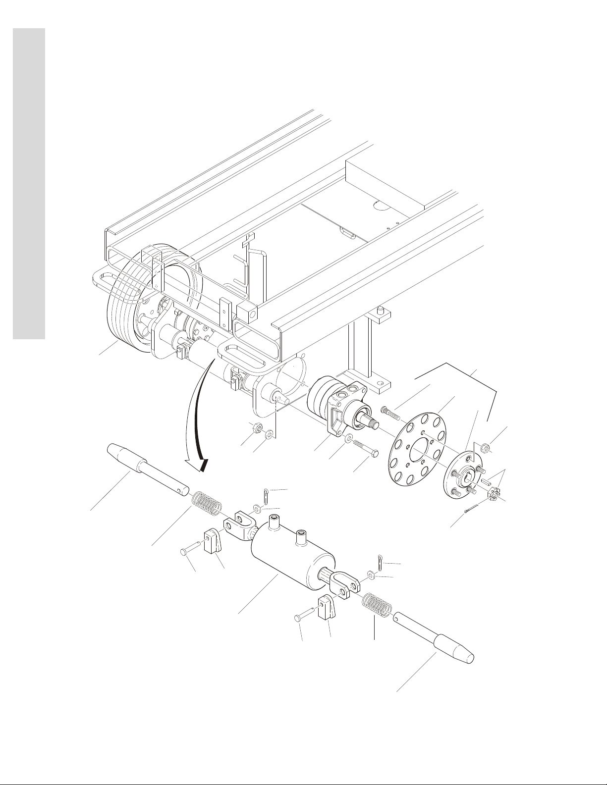
FIGURE 1-5. WHEEL DRIVE AND BRAKE INSTALLATIONS - 2032E2/2632E2/ 2646E2/3246E2
1-14 3120738
Page 21

SECTION 1 FRAME
.
FIGURE 1-5. WHEEL DRIVE AND BRAKE INSTALLATIONS - 2032E2/2632E2/2646E2/3246E2
FIG & ITEM # PART NUMBER DESCRIPTION QTY. REV.
WHEEL DRIVE INSTALLATION OPTIONS: Ref.
0257626 2032E2 Machines Ref. I
0271228 2632E2 Machines Ref. A
0257876 2646E2 Machines Ref. J
0258898 3246E2 Machines (Prior to S/N 90855) Ref. G
0271228 3246E2 Machines (S/N 90855 to Present) Ref. B
1Options: 8
0681822 (Bolt 1/2”-13NC x 2 3/4” Grade 8)
0681828 (Bolt 1/2”-13NC x 3 1/4” Grade 8)
2 Hub Assembly Options: 2
2780222 2032E2/2646E2 Machines
2632E2/3246E2 Machines Options:
2780238 Prior to S/N 90854
2780222 S/N 90855 to S/N 98951
See Note: S/N 98952 to S/N 99050
Note: For machines in this range contact JLG
Industries Inc.
2780238 S/N 99051 to S/N 102610
See Note: S/N 102611 to S/N 102640
Note: For machines in this range contact JLG
Industries Inc.
2780222 S/N 102641 to Present
2A 7012613 Stud, Wheel (5 per Hub) 10
2B 1760167 Disc, Brake 2
2C 2780216 Hub (Used w/2780222 Assembly) 2
Not Available Hub (Used w/2780238 Assembly - Purchase Assem-
bly)
3 Drive Motor Assembly Options: A/R
Note: Use Like Motors on Both Left & Right Sides Ref.
2032E2 Motor Options: Ref.
Use 2910312 2032E2 (Prior to S/N 86447) (Was p/n 3160230) 2
3160258 2032E2 (S/N 86447 to S/N 90870) 2
3160230 & 3160258 Replacement Parts:
7018996 Key, Shaft 1
7018997 Nut, Castle 1
7021312 Seal, Shaft Oil (Inner Seal) 1
7021317 Seal, Dust (Outer Seal) 1
7023874 Cap, End 1
3160263 2032E2 (S/N 90870 to Present) (See Figure 1-6 for
Breakdown)
2646E2 Motor Options: Ref.
Use 2910313 2646E2 (Prior to S/N 87548) (Was p/n 3160226) 2
3160259 2646E2 (S/N 87548 to 90870) 2
3160226 & 3120259 Replacement Parts:
7018996 Key, Shaft 1
7018997 Nut, Castle 1
7021312 Seal, Shaft Oil (Inner Seal) 1
7021317 Seal, Dust (Outer Seal) 1
Ref.
Ref.
2
2
S
E
C
T
I
O
N
1
F
R
A
M
E
3120738 1-15
Page 22

SECTION 1 FRAME
S
E
C
T
I
O
N
1
F
R
A
M
E
FIGURE 1-5. WHEEL DRIVE AND BRAKE INSTALLATIONS - 2032E2/2632E2/2646E2/3246E2
(CONTINUED)
FIG & ITEM # PART NUMBER DESCRIPTION QTY. REV.
3 (cont’d) 7023874 Cap, End 1
2632E2/3246E2 Motor Options: Ref.
Use 2910342 Prior to S/N 62566 (was p/n 3160236 - Rexroth Motor) 2
Use 2910342 S/N 62566 to S/N 90854 (was p/n 3160247 - Rexroth
Motor)
3160236 & 3160247 Replacement Parts:
See Note Key, Shaft (was p/n 7022516) 1
See Note Nut, Castle (was p/n 7022515) 1
See Note Seal, Shaft Oil (Inner Seal) (was p/n 7022517) 1
See Note Seal, Dust (Outer Seal) (was p/n 7022518) 1
See Note Seal, Ring (was p/n 7022519) 1
Note: Replacement Parts are no longer available for
motor p/ns 3120236 & 3160247 - Use Kit p/n 2910342)
Note: For replacement parts for 2910342 see Figure 1-6 Ref.
3160265 S/N 90855 to S/N 98951 (Parker Hannofin Motor) (See
Figure 1-6 for Breakdown)
See Note: S/N 98952 to S/N 99050 2
Note: For machines in this range contact JLG
Industries Inc.
Use 3160265 S/N 99051 to S/N 102610 (Rexroth Motor) (was p/n
3160247 - Rexroth Motor)
See Note: S/N 102611 to S/N 102640 2
Note: For machines in this range contact JLG
Industries Inc.
3160265 S/N 102641 to Present (Parker Hannofin Motor) 2
4 Hardware Options: 8
3271805 Locknut 1/2”-13NC (Grade 8) (Prior to S/N 49303)
3311801 Nut 1/2”-13NC (S/N 49303 to S/N 84080)
3300450 Nut 1/2”-13NC (S/N 84080 to Present)
5 Pin, Cotter Options: 2
3450406 2032E2/2646E2 Machines (1/8” x 1 1/2”)
3450508 3246E2 Machines (1/4” x 2”) (Prior to S/N 90855)
3450406 3246E2 Machines (1/8” x 1 1/2”) (S/N 90855 to Present)
6 Flatwasher Options: A/R
4711800 2032E2/2646E2 Machines (Prior to S/N 87549)
4740453 2032E2/2646E2 Machines (S/N 87549 to Present)
4740453 3246E2 (S/N 102645 to Present)
7 3300255 Nut, Wheel 10
8 4761800 Flatwasher 1/2” (S/N 49303 to S/N 84080) 8
9 0100019 Loctite #271 (Prior to S/N 84080) A/R
2
Ref.
2
Ref.
2
Ref.
BRAKE INSTALLATION OPTIONS: Ref.
0257877 2032E2 / 2632E2 Machines Ref. D
0257878 2646E2 / 3246E2 Machines Ref. D
101 Brake Cylinder Assembly Options
(See Section 5 for Breakdown):
Use 1683833 Prior to S/N 65498 (Was p/n 1683557)
1683833 S/N 65498 to Present
102 3430620 Pin 2
1-16 3120738
1
Page 23

SECTION 1 FRAME
FIGURE 1-5. WHEEL DRIVE AND BRAKE INSTALLATIONS - 2032E2/2632E2/2646E2/3246E2
(CONTINUED)
FIG & ITEM # PART NUMBER DESCRIPTION QTY. REV.
103 3450403 Pin, Cotter 1/8” x 3/4” 2
104 Rod Options: 2
3841332 2032E2 Machines
3841371 2646E2/3246E3 Machines
105 4160137 Spring, Compression 2
106 4711600 Flatwasher 3/8” Narrow 2
107 4845037 Brake Cam Weldment 2
TIRE AND WHEEL INSTALLATION OPTIONS: Ref.
0255682 Gray Non-Marking Tire Installation Ref. —
0271541 Low Profile, Non-Marking Tire Installation (2632E2) Ref.
0255679 Black Tire Installation Ref. —
200 4520176 5x16 Gray Non-Marking (Standard) 4
4520257 5x16 Low Profile, Non-Marking (2632E2) 4
4520174 5x16 Black (Optional) 4
S
E
C
T
I
O
N
1
F
R
A
M
E
3120738 1-17
Page 24

SECTION 1 FRAME
TORQUE TO
50 FT. LBS.
12
11
4
9
87
5
2
63
191
618151415
1720113
4444
10
1
01100
S
E
C
T
I
O
N
1
F
R
A
M
E
FIGURE 1-6. DRIVE MOTOR ASSEMBLY - (2032E2/2646E2 S/N 90870 TO PRESENT) (2632E2/3246E2 S/N 90855 TO PRESENT)
1-18 3120738
Page 25

SECTION 1 FRAME
.
FIGURE 1-6. DRIVE MOTOR ASSEMBLY - (2032E2/2646E2 S/N 90870 TO PRESENT) (2632E2/
3246E2 S/N 90855 TO PRESENT)
FIG & ITEM # PART NUMBER DESCRIPTION QTY. REV.
DRIVE MOTOR ASSEMBLIES (PARKER HANNIFIN) Ref.
3160263 DRIVE MOTOR - 2032E2 Ref. B
3160264 DRIVE MOTOR - 2646E2 Ref. B
3160265 DRIVE MOTOR - 2632E2/3246E2 Ref. B
2910342 DRIVE MOTOR - 3246E2 (This kit uses p/n 3160301 Motor) Ref. A
1 Housing Options: 1
7023307 3160263, 3160264 & 3160265
Not Serviced 3160301
2 7023308 Bearing, Thrust 1
3 Shaft Options: 1
7023309 3160263 & 3160264
Not Serviced 3160265
7026178 3160301
4 7023310 Ring, Seal 5
5 7023311 Plate, Wear 5
6 Drive Link Options: 1
7023312 3160263
7023326 3160264
7023410 3160265 & 3160301
7 Assembly, Rotor Options: 1
7023313 3160263
7023327 3160264
7023409 3160265 & 3160301
8 7023314 Manifold 1
9 7023315 Assembly, Commutator 1
10 7023318 Seal, Commutator 1
11 Cover, End Options: 1
7023316 3160263
7023328 3160264, 3160265 & 3160301
12 Bolt Options: 7
7023317 3160263
7023329 3160264 & 3160265
Not Serviced 3160301
13 See Note Seal (Note: Use Items 100 & 101) 1
14 Not Available Identification Tag N/A
15 7023320 Screw 2
16 See Note Ring Back-Up (Note: Use Items 100 & 101) 1
17 See Note Washer, Back-Up (Note: Use Items 100 & 101) 1
18 See Note Seal, Shaft (Note: Use Items 100 & 101) 1
19 Key Options: 1
7023324 3160263, 3160264 & 3160265
7026179 3160301
20 Nut, Castle Options: 1
7023325 3160263, 3160264 & 3160265
7026180 3160301
S
E
C
T
I
O
N
1
F
R
A
M
E
3120738 1-19
Page 26

SECTION 1 FRAME
S
E
C
T
I
O
N
1
F
R
A
M
E
FIGURE 1-6. DRIVE MOTOR ASSEMBLY - (2032E2/2646E2 S/N 90870 TO PRESENT) (2632E2/
3246E2 S/N 90855 TO PRESENT) (CONTINUED)
FIG & ITEM # PART NUMBER DESCRIPTION QTY. REV.
21 Bearing, Inner Options (Not Shown): 1
Not Required 3160263 & 3160234
7023405 3160265
7026174 3160301
22 Washer, Thrust Options (Not Shown): A/R
Not Required 3160263 & 3160234 0
7023406 3160265 1
7026175 3160301 2
23 Bearing, Thrust Options (Not Shown): 1
Not Required 3160263 & 3160234
7023407 3160265
7026176 3160301
24 Bearing, Outer Options (Not Shown): 1
Not Required 3160263 & 3160234
7023408 3160265
7026177 3160301
KIT OPTIONS: Ref.
Kit, Seal Options (Includes Items 4, 10, 13, 16, 17 & 18):
100 7023412 3160263, 3160264 & 3160265 1
101 7026181 3160301 1
1-20 3120738
Page 27

SECTION 1 FRAME
FIGURE 1-6. DRIVE MOTOR ASSEMBLY - (2032E2/2646E2 S/N 90870 TO PRESENT) (2632E2/
3246E2 S/N 90855 TO PRESENT) (CONTINUED)
FIG & ITEM # PART NUMBER DESCRIPTION QTY. REV.
S
E
C
T
I
O
N
1
F
R
A
M
E
3120738 1-21
Page 28
SECTION 1 FRAME
771
769
772
717
755
751
766
770
NOTE: SEE SECTION 3
FOR ARM GUARD
LIMIT SWITCH
768
755
765
766
767
501
603
602
603B
603A
2
4
1
601
604
606
304
LOCATION
MAY VARY
301
303
A
402
403
404
409
405
D
201
202A
127
128
203
114
131
125
118
151
130
147
202
E
AFD
E
B
C
874
974
820
920
863
963
863
963
873
973
876
976
838
938
875
975
859
959
872
972
C
F
B
5
401
S
E
C
T
I
O
N
1
F
R
A
M
E
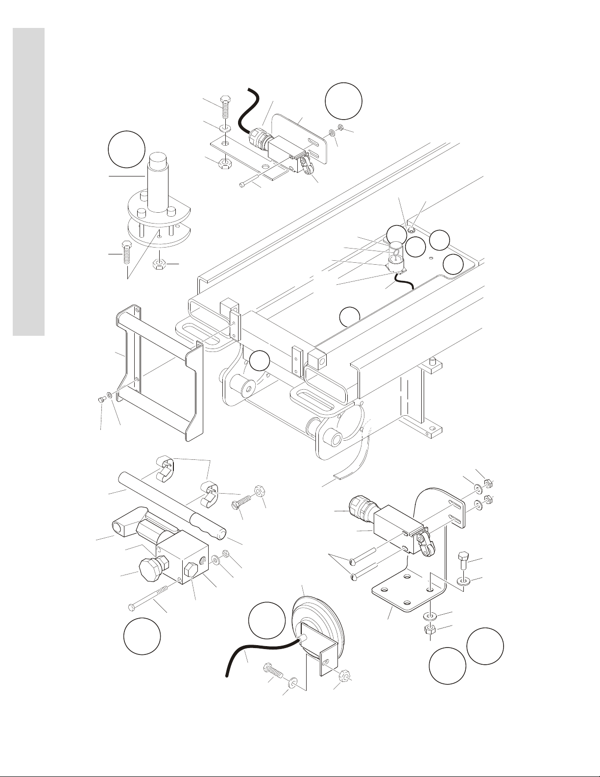
FIGURE 1-7. FRAME MOUNTED COMPONENTS INSTALLATIONS
1-22 3120738
Page 29

SECTION 1 FRAME
.
FIGURE 1-7. FRAME MOUNTED COMPONENTS INSTALLATIONS
FIG & ITEM # PART NUMBER DESCRIPTION QTY. REV.
LADDER INSTALLATIONS Ref.
0257662 1532E2 Ref. B
0257662 1932E2 Ref. B
0257662 2032E2 without Optional Invertor Ref. B
0258681 2032E2 with Optional Invertor Ref. A
0257779 2632E2 Ref. A
0257779 2646E2 Ref. A
0258944 3246E2 Ref. A
1 0100011 Loctite #242 A/R
2 4711600 Flatwasher 3/8” Narrow 4
3 Not Used
4 Ladder Weldment Options: 1
4845558 1532E2
4845558 1932E2
4845558 2032E2 without Optional Invertor
4845837 2032E2 with Optional Invertor
4845834 2632E2
4845834 2646E2
4845922 3246E2
5 0641605 Bolt 3/8”-16NC x 5/8” 4
S
E
C
T
I
O
N
1
F
R
A
M
E
MANUAL DESCENT PUMP INSTALLATION
(PRIOR TO S/N 69053 ONLY)
0257666 2646E2 Machines Only Ref. M
0258889 3246E2 Machines Only Ref. F
101 to 113 Not Used
114 0641528 Bolt 5/16”-18NC x 3 1/2” 2
115 to 117 Not Used
118 0721006 Screw, Machine #10-24NC x 3/4” 2
119 to 124 Not Used
125 1380136 Clip, Gripper 2
126 Not Used
127 2560122 Handle, Pump 1
128 2560123 Handle, Grip
129 Not Used
130 3311005 Locknut #10-24NC 4
131 3311505 Locknut 5/16”-18NC 2
132 to 146 Not Used
147 4640859 Pump Assembly - Manual Descent
(See 201-203 for Breakdown)
148 to 149 Not Used
150 0100001 Adhesive, Weatherstrip (Not Shown) A/R
151 4751500 Flatwasher 5/16” 2
Ref.
1
3120738 1-23
Page 30

SECTION 1 FRAME
S
E
C
T
I
O
N
1
F
R
A
M
E
FIGURE 1-7. FRAME MOUNTED COMPONENTS INSTALLATIONS (CONTINUED)
FIG & ITEM # PART NUMBER DESCRIPTION QTY. REV.
4640859 PUMP ASSEMBLY - MANUAL DESCENT
(2646E2 & 3246E2 MACHINES ONLY)
201 7012952 Cartridge, Pump 1
2900708 Seal Kit - 7012952 Cartridge 1
202 7012954 Cartridge, Needle Valve 1
7012953 Seal Kit - 7012954 Cartridge 1
202A 7012961 Knob 1
203 7012955 Cartridge, Check 1
7012540 Seal Kit - 7012955 Cartridge 1
TILT INDICATOR INSTALLATIONS Ref.
All Specs except Japanese Spec: Ref.
0270066 1532E2 (1.5°) Ref. B
0257969 1932E2/2032E2/2646E2 Prior to S/N 71686 (5°) Ref. C
0270066 1932E2/2032E2 S/N 71686 to Present (1.5°) Ref. B
0257799 2632E2 (2°) Ref. A
0259410 2632E2 with Prop Controls (2°) Ref. A
0257799 2646E2 S/N 71686 to Present (2°) Ref. A
0257969 3246E2 with Std Controls Prior to S/N 71686 (5°) Ref. C
0257799 3246E2 with Std Controls S/N71686 to Present (2°) Ref. D
0259410 3246E2 with Prop Controls (2°) Ref. A
Japanese Spec: Ref.
0257969 1532E2 (5°) Ref. A
0257969 1932E2/2032E2/2646E2 Prior to S/N 71686 (5°) Ref. C
0270066 1932E2/2032E2 S/N 71686 to S/N 79269 (1.5°) Ref. B
0257969 1932E2/2032E2 S/N 79269 to Present (5°) Ref. C
0257969 2632E2 (°5) Ref. C
0257799 2646E2 S/N 71686 to S/N 79269 (2°) Ref. A
0257969 2646E2 S/N 71686 to Present (5°) Ref. A
0257969 3246E2 with Std Controls Prior to S/N 71686 (5°) Ref. C
0257799 3246E2 with Std Controls S/N 71686 to S/N 79269 (2°) Ref. D
0257969 3246E2 with Std Controls S/N 71686 to Present (5°) Ref. D
0259410 3246E2 with Prop Controls Prior to S/N 79269 (2°) Ref. A
0257969 3246E2 with Prop Controls S/N 71686 to Present (5°) Ref. D
Ref.
301 0641405 Bolt 1/4”-20NC x 5/8” 2
302 Not Used
303 3311405 Locknut 1/4”-20NC 2
304 Indicator, Tilt Options: 1
4360487 1.5°
4360349 2° (Standard Controls Machines)
4360435 2° (Prop Controls Machines)
4360348 5°
1-24 3120738
Page 31

SECTION 1 FRAME
FIGURE 1-7. FRAME MOUNTED COMPONENTS INSTALLATIONS (CONTINUED)
FIG & ITEM # PART NUMBER DESCRIPTION QTY. REV.
HORN INSTALLATIONS (OPTIONAL) Ref.
0258317 1532E2 & 1932E2 Machines Ref. B
0257802 2032E2 & 2646E2 & 3246E2 Machines Ref. D
0257802 3246E2 Standard Control Machines Ref. D
0259655 3246E2 Proportional Control Machines Ref. B
0271917 2632E2 Standard Control Machines Ref. B
0271926 2632E2 Proportional Control Machines Ref. A
401 0100048 Grease, Dialectic A/R
402 0140022 Horn 1
403 Bolt Options: 1
0641505 Bolt 5/16”-18NC x 5/8” (1532E2/1932E2/2632E2)
0641510 Bolt 5/16”-18NC x 1 1/4” (2032E2/2646E2/3246E2)
404 Cable/Harness, Electrical
1060680 1532E2/1932E2 Machines (Cable, Electrical - 16/2) A/R
1060680 2032E2/2646E2 Machines (Cable, Electrical - 16/2) 8ft/2.4m
1060680 3246E2 Standard Control Machines
(Cable, Electrical - 16/2)
1060680 2632E2 Standard Control Machines
(Cable, Electrical - 18/2)
4922258 3246E2/2632E2 Proportional Control Machines
(Harness - See Section 7 for Breakdown)
405 3311505 Locknut 5/16”-18NC 1
406 to 408 Not Used
409 4751500 Flatwasher 5/16” 1
8ft/2.4m
5ft/1.53m
1
S
E
C
T
I
O
N
1
F
R
A
M
E
0258581 STATIC STRAP INSTALLATION Ref. B
501 3941406 Screw, Self-Tapping 1/4”-20NC x 3/4” 1
Use 4240147 Strap, Static (Was 4240084) 1
4751400 Flatwasher 1/4” 1
BEACON LIGHT INSTALLATION OPTIONS: Ref.
0258318 (1532E2 & 1932E2) (Optional) Ref. A
0257801 (2032E2 / 2646E2 / 3246E2) Standard Controls (Optional) Ref. A
0259411 (3246E2) Proportional Controls (Optional) Ref. A
0271891 (2632E2) Standard Controls (Optional) Ref. B
0271925 (2632E2) Proportional Controls (Optional) Ref. A
601 Screw, Socket Head Options: 2
0721006 1532E2 / 1932E2
0721004 2632E2
602 1060680 Cable, Electrical 18/2 A/R
603 2920146 Beacon Light Assembly 1
603A 7016319 Bulb 1
603B Lens Options: 1
7016372 Amber
2920166 Blue
604 3311005 Locknut #10-24NC 2
3120738 1-25
Page 32

SECTION 1 FRAME
S
E
C
T
I
O
N
1
F
R
A
M
E
FIGURE 1-7. FRAME MOUNTED COMPONENTS INSTALLATIONS (CONTINUED)
FIG & ITEM # PART NUMBER DESCRIPTION QTY. REV.
605 4460248 Terminal (Not Shown) 2
606 4751000 Flatwasher #10 2
DRIVE SPEED SWITCH INSTALLATION
(1532E2 & 1932E2 ONLY)
0270502 1532E2 Ref. C
0258014 1932E2 Ref. J
701 to 716 Not Used
717 0641405 Bolt 1/4”-20NC x 5/8” 2
718 to 750 Not Used
751 4460662 Connector, Strain Relief 1
718 to 754 Not Used
755 4711400 Washer 1/4”, Narrow 6
756 to 764 Not Used
765 0641406 Bolt 1/4”-20NC x 3/4” (S/N 50027 to Present) 4
766 3311405 Locknut 1/4”-20NC 6
767 3570991 Plate, Cover 1
768 3911024 Screw #10-24NC x 1 1/2” 2
769 4360401 Switch, Limit 1
770 3311005 Locknut #10-24NC 2
771 4751000 Washer #10, Wide 2
772 0902501 Bracket, Limit Switch 1
Ref.
DRIVE SPEED SWITCH INSTALLATION (3246E2 ONLY)
(REFERENCE LETTER “C” ON ART)
Note: See Section 10 for Japanese Taiyo Spec Ref.
0258889 Standard Control Machines Ref. L
0259408 Proportional Control Machines Ref. H
801 to 819 Not Used
820 0641405 Bolt 1/4”-20NC x 5/8” 4
821 to 837 Not Used
838 3311005 Locknut #10-24NC 2
839 to 858 Not Used
859 4460662 Connector, Strain Relief 1
860 to 862 Not Used
863 4711400 Flatwasher 1/4” Narrow 8
864 to 871 Not Used
872 0902537 Bracket 1
873 3311405 Locknut 1/4”-20NC 4
874 3911024 Screw, Round Head #10-24NC x 3” 2
875 4360401 Switch, Limit 1
876 4751000 Flatwasher #10 8
877 Harness, Elevation Options:
(Not Shown - See Section 7 for Breakdown)
Not Required Standard Controls Machines
4922305 Proportional Control Machines
Ref.
A/R
1-26 3120738
Page 33

SECTION 1 FRAME
FIGURE 1-7. FRAME MOUNTED COMPONENTS INSTALLATIONS (CONTINUED)
FIG & ITEM # PART NUMBER DESCRIPTION QTY. REV.
OVERLOAD PROTECTION SWITCH INSTALLATION
(JAPANESE SPEC ONLY)
(REFERENCE LETTER “F” ON ART)
Note: See Section 10 for Japanese Taiyo Spec Ref.
0258733 1532E2 & 1932E2 Ref. E
0257976 2032E2 Ref. G
0258651 2646E2 & 3246E2 Ref. E
901 to 919 Not Used
920 Bolt (1/4”-20NC x 1”) Options: 2
0641406 1532E2 & 1932E2
0641406 2032E2 / 2646E2 & 3246E2 (Prior to S/N 93070)
0641408 2032E2 / 2646E2 & 3246E2 (S/N 93070 to Present)
921 to 937 Not Used
938 3310801 Locknut #8-32NC 2
939 to 958 Not Used
959 Connector, Strain Relief Options: 1
4460049 2032E2 / 2646E2 & 3246E2
4460049 1532E2 & 1932E2 (Prior to S/N 93070)
4460662 1532E2 & 1932E2 (S/N 93070 to Present)
960 to 962 Not Used
963 4711400 Flatwasher 1/4” Narrow 8
964 to 971 Not Used
972 Bracket Options: 1
0902500 1532E2 & 1932E2 (Prior to S/N 80167)
0902691 1532E2 & 1932E2 (S/N 80167 to Present)
0902482 2032E2 & 2646E2 & 3246E2
Cover Bracket Options (Not Shown): 1
Not Required 1532E2 & 1932E2
0962632 2032E2 & 2646E2 & 3246E2
973 3311405 Locknut 1/4”-20NC 4
974 0720812 Screw, Round Head #10-24NC x 3” 2
975 4360437 Switch, Limit 1
976 4750800 Flatwasher #8 8
Ref.
S
E
C
T
I
O
N
1
F
R
A
M
E
3120738 1-27
Page 34

SECTION 1 FRAME
S
E
C
T
I
O
N
1
F
R
A
M
E
FIGURE 1-7. FRAME MOUNTED COMPONENTS INSTALLATIONS (CONTINUED)
FIG & ITEM # PART NUMBER DESCRIPTION QTY. REV.
1-28 3120738
Page 35

SECTION 2
FIGURE DESCRIPTION PAGE
2-1 Hydraulic Components Installation - 1532E2/1932E2 (Left Side) . . . . . . . . . . . . . . . . . . . . . . . . 2-2
2-2 Hydraulic Components Installation - 2032E2/2632E2/2646E2/3246E2 (Left Side) . . . . . . . . . . 2-6
2-3 Valve Assembly - Standard Controls Machines . . . . . . . . . . . . . . . . . . . . . . . . . . . . . . . . . . . . . 2-10
2-4 Valve Assembly - Proportional Controls Machines . . . . . . . . . . . . . . . . . . . . . . . . . . . . . . . . . . . 2-14
2-5 Electrical Components Installations (Left Side of Machines with Standard Controls). . . . . . . . . 2-18
2-6 Electrical Components Installations (Left Side of Machines with Proportional Controls) . . . . . . 2-22
2-7 Electrical Components Installations (Right Side) . . . . . . . . . . . . . . . . . . . . . . . . . . . . . . . . . . . . 2-26
2-8 Battery Charger Assemblies . . . . . . . . . . . . . . . . . . . . . . . . . . . . . . . . . . . . . . . . . . . . . . . . . . . . 2-30
2-9 Pothole Protection and Tray Installations . . . . . . . . . . . . . . . . . . . . . . . . . . . . . . . . . . . . . . . . . . 2-34
GROUND COMPONENTS
TABLE OF CONTENTS
S
E
C
T
I
O
N
2
G
R
O
U
N
D
C
O
M
P
O
N
E
N
T
S
3120738 2-1
Page 36

S
4
2
1
41510612A12B917
11
23
162124
8
3
12
13
12C13
5
7
6
1
6
11E
11D
11C
11
B
11A
19
16
18
9
22
25
1
E
C
T
I
O
N
2
G
R
O
U
N
D
C
O
M
P
O
SECTION 2 GROUND COMPONENTS
FIGURE 2-1. HYDRAULIC COMPONENT INSTALLATIONS - 1532E2/1932E2
N
E
N
T
S
2-2 3120738
Page 37

SECTION 2 GROUND COMPONENTS
.
FIGURE 2-1. HYDRAULIC COMPONENT INSTALLATIONS - 1532E2/1932E2
FIG & ITEM # PART NUMBER DESCRIPTION QTY. REV.
HYDRAULIC COMPONENTS INSTALLATIONS 1532E2 &1932E2 (LEFT SIDE) OPTIONS:
0258056 (Prior to S/N 90870) Ref. G
0271222 (S/N 90870 to Present) Ref. A
1 0100020 Sealant, Pipe A/R
2 0641405 Bolt 1/4”-20NC x 5/8” 2
3 0641508 Bolt 5/16”-18NC x 1” 7
4 0902486 Bracket, Filter Mounting 1
5 0902490 Bracket, Tank 1
6 1320030 Clamp, Hose 2
7 1340052 Breather, Tank 1
8 2120105 Filter Assembly 1
2120072 Element, Filter 1
9 3311505 Locknut 5/16”-18NC 3
10 3520077 Plug, Snap 1
11 Motor/Pump Assembly Options: 1
3600288 Prior to S/N 90870
3600325 S/N 90870 to Present
11A 7011041 Motor 1
7010639 Brush 2
7010640 Spring 8
11B Pump Options: 1
7011050 Prior to S/N 90870
7011049 S/N 90870 to Present
7011045 Gasket Kit 1
7010903 Seal, Shaft 1
11C 7010944 Coupling Kit 1
11D 7011043 Screw, Pump Mounting 4
11E 7011044 Gasket 1
12 4400415 Tank, Hydraulic 1
12A 1120491 Lid 1
12B 3780199 O-Ring 1
12C Not Available Plug 1
13 4420038 Tape, Rubatex
14 4567681 Tube, Supply 1
15 4567682 Tube, Return 1
16 4751400 Flatwasher 1/4” 5
17 4751500 Flatwasher 5/16” 10
18 0641406 Bolt 1/4”-20NC x 3/4” 3
19 4641020 Valve Assembly (See Figure 2-3 for Breakdown) 1
20 Not Used
21 0641410 Bolt 1/4”-20NC x 1 1/4” (S/N 49355 to Present) 2
22 0641510 Bolt 5/16”-18NC x 1 1/4” (S/N 49355 to Present) 1
23 Cylinder, Cushion Options: A/R
Not Required Prior to S/N 49355 0
Use 1683834 S/N 49355 to S/N 65498 (Was p/n 1683560) 1
1683834 S/N 65498 to Present 1
Ref.
25in/64cm
S
E
C
T
I
O
N
2
G
R
O
U
N
D
C
O
M
P
O
N
E
N
T
S
3120738 2-3
Page 38

S
E
C
T
I
O
N
2
G
R
O
SECTION 2 GROUND COMPONENTS
FIGURE 2-1. HYDRAULIC COMPONENT INSTALLATIONS - 1532E2/1932E2 (CONTINUED)
FIG & ITEM # PART NUMBER DESCRIPTION QTY. REV.
24 3311405 Locknut 1/4”-20NC (S/N 49355 to Present) 2
25 0100011 Loctite #242 A/R
U
N
D
C
O
M
P
O
N
E
N
T
S
2-4 3120738
Page 39

SECTION 2 GROUND COMPONENTS
FIGURE 2-1. HYDRAULIC COMPONENT INSTALLATIONS - 1532E2/1932E2 (CONTINUED)
FIG & ITEM # PART NUMBER DESCRIPTION QTY. REV.
S
E
C
T
I
O
N
2
G
R
O
U
N
D
C
O
M
P
O
N
E
N
T
S
3120738 2-5
Page 40

18
116
116A
18A
116D
18D
18E
116E
18C
116C
116B
18B
16
114
26
125
124
122
29
127
(Standard
Controls
Machines
Shown)
(Standard Controls
Machines Only)
(Standard
Controls
Machines)
(Proportional
Controls
Machines)
3
27
24
23
25
124
126
28
6
105
101
24
123
12
111
118A
118B
118
19A
19B
19
10
110
121
21
101
9
9
108
108
109
17
8
107
114
117
113
115
119
112
118C
15
25
125
6
106
11
4
24
141319C
7
106
101
20
13030230
120
1012230
103
104
102
S
E
C
T
I
O
N
2
G
R
O
U
N
D
C
O
M
P
SECTION 2 GROUND COMPONENTS
FIGURE 2-2. HYDRAULIC COMPONENT INSTALLATIONS - 2032E2/2632E2/ 2646E2/3246E2
O
N
E
N
T
S
2-6 3120738
Page 41

SECTION 2 GROUND COMPONENTS
.
FIGURE 2-2. HYDRAULIC COMPONENT INSTALLATIONS - 2032E2/2632E2/2646E2/3246E2
FIG & ITEM # PART NUMBER DESCRIPTION QTY. REV.
HYDRAULIC COMPONENTS INSTALLATIONS:
(WITH STANDARD CONTROLS)
0257659 2032E2/ 2646E2 Prior to S/N 64779 Ref. B
0259280 2032E2/ 2646E2 S/N 64779 to Present Ref. F
0259280 2632E2 / 3246E2 with Standard Controls Ref. F
Ref.
S
E
C
T
1 0100020 Sealant, Pipe A/R
2 0641405 Bolt 1/4”-20NC x 5/8” 2
3 0641406 Bolt 1/4”-20NC x 3/4” 2
4 0641407 Bolt 1/4”-20NC x 7/8” 2
5 Not Used
6 0641508 Bolt 5/16”-18NC x 1” 5
7 Bolt Options: 4
0641624 2032E2/ 2646E2 Prior to S/N 64779
0641620 2032E2/ 2646E2 S/N 64779 to Present & All 3246E2
8 Bracket, Tank Hold Down Options: 1
0902198 2032E2/ 2646E2 Prior to S/N 64779
0902538 2032E2/ 2646E2 S/N 64779 to Present & All 3246E2
9 Clamp, Hose 2
Use 1320030 Prior to S/N 88558 (Was p/n 1320033)
1320030 S/N 88558 to Present
10 1340052 Breather, Tank 1
11 Cylinder, Cushion Options: 1
Use 1683834 Prior to S/N 65498 (Was p/n 1683560)
1683834 S/N 65498 to Present
12 2120105 Filter Assembly 1
2120072 Element, Filter 1
13 2200233 Plug, Drain (Prior to S/N 71406 Only) 1
14 3311405 Locknut 1/4”-20NC 2
15 3311505 Locknut 5/16”-18NC 1
16 3311605 Locknut 3/8”-16NC 4
17 3520077 Plug, Snap 1
18 3600270 Motor/Pump Assembly 1
18A 7011041 Motor 1
7010639 Brush 2
7010640 Spring 8
18B 7011042 Pump 1
7011045 Gasket Kit 1
7010903 Seal, Shaft 1
18C 7010944 Coupling Kit 1
18D 7011043 Screw, Pump Mounting 4
18E 7011044 Gasket 1
19 Tank, Hydraulic Options: 1
Use 4400422 2032E2/ 2646E2 Prior to S/N 64779 (Was p/n
4400406)
4400422 2032E2/ 2646E2 S/N 64779 to Present
Use 4400422 3246E2 Prior to S/N 57891 (Was p/n 4400406)
4400422 3246E2 S/N 57891 to Present
19A 1120491 Lid 1
I
O
N
2
G
R
O
U
N
D
C
O
M
P
O
N
E
N
T
S
3120738 2-7
Page 42

S
E
C
T
I
O
N
2
G
R
O
U
N
D
C
O
M
P
O
N
E
N
T
S
SECTION 2 GROUND COMPONENTS
FIGURE 2-2. HYDRAULIC COMPONENT INSTALLATIONS - 2032E2/2632E2/2646E2/3246E2
FIG & ITEM # PART NUMBER DESCRIPTION QTY. REV.
19B 3780199 O-Ring 1
19C 2200233 Plug, Drain (S/N 71406 to Present Only) 1
20 4420038 Tape, Rubatex
21 4567271 Tube, Return 1
22 Tube, Supply Options: 1
Use 4567272 3246E2 Prior to S/N 88558 (Was p/n 4567893)
23 4641020 Valve Assembly (See Figure 2-3 for Breakdown) 1
24 4751400 Flatwasher 1/4” 6
25 4751500 Flatwasher 5/16” 6
26 4751600 Flatwasher 3/8” 8
27 4761400 Lockwasher 1/4” (Prior to S/N 50361) 3
28 4761500 Lockwasher 5/16” 4
29 Counterweight 1
4845664 2032E2/ 2646E2 Prior to S/N 64779
4846017 2032E2/ 2646E2 S/N 64779 to Present & All 3246E2
30 0100011 Loctite #242 A/R
HYDRAULIC COMPONENTS INSTALLATIONS
(WITH PROPORTIONAL CONTROLS)
0259416 2632E2 / 3246E2 with Proportional Controls Ref. C
101 0100011 Loctite #242 A/R
102 0100020 Sealant, Pipe A/R
103 0641405 Bolt 1/4”-20NC x 5/8” 2
104 0641505 Bolt 5/16”-18NC x 5/8” 2
105 0641508 Bolt 5/16”-18NC x 1” 4
106 0641622 Bolt 3/8”-16NC x 2 3/4” 4
107 0902574 Bracket, Tank Hold Down 1
108 Clamp, Hose 2
Use 1320030 Prior to S/N 88558 (Was p/n 1320033)
109 1320242 Clamp, Hose 1
110 1340052 Breather, Tank 1
111 2120105 Filter Assembly 1
2120072 Element, Filter 1
112 2200233 Plug, Drain (Prior to S/N 71406 Only) 1
113 3310601 Nut #6-32NC 1
114 3311605 Locknut 3/8”-16NC 4
115 3520077 Plug, Snap 1
116 3600270 Motor/Pump Assembly 1
116A 7011041 Motor 1
7010639 Brush 2
7010640 Spring 8
116B 7011042 Pump 1
7011045 Gasket Kit 1
7010903 Seal, Shaft 1
116C 7010944 Coupling Kit 1
116D 7011043 Screw, Pump Mounting 4
116E 7011044 Gasket 1
117 4360461 Switch, Temperature 1
41in/1m
Ref.
2-8 3120738
Page 43

SECTION 2 GROUND COMPONENTS
FIGURE 2-2. HYDRAULIC COMPONENT INSTALLATIONS - 2032E2/2632E2/2646E2/3246E2
FIG & ITEM # PART NUMBER DESCRIPTION QTY. REV.
118 4400422 Tank, Hydraulic 1
118A 1120491 Lid 1
118B 3780199 O-Ring 1
118C 2200233 Plug, Drain (S/N 71406 to Present Only) 1
119 4420038 Tape, Rubatex
120 4567271 Tube, Return 1
121 Tube, Supply Options: 1
Use 4567272 3246E2 Prior to S/N 88558 (Was p/n 4567893)
122 4641036 Valve Assembly (See Figure 2-4 for Breakdown) 1
123 4751400 Flatwasher 1/4” 2
124 4751500 Flatwasher 5/16” 6
125 4751600 Flatwasher 3/8” 8
126 4761500 Lockwasher 5/16” 4
127 4846040 Counterweight 1
41in/1m
S
E
C
T
I
O
N
2
G
R
O
U
N
D
C
O
M
P
O
N
E
N
T
S
3120738 2-9
Page 44

S
E
C
T
I
O
N
2
G
R
O
SECTION 2 GROUND COMPONENTS
FIGURE 2-3. VALVE ASSEMBLY - STANDARD CONTROLS MACHINES
U
N
D
C
O
M
P
O
N
E
N
T
S
2-10 3120738
Page 45

SECTION 2 GROUND COMPONENTS
.
FIGURE 2-3. VALVE ASSEMBLY - STANDARD CONTROLS MACHINES
FIG & ITEM # PART NUMBER DESCRIPTION QTY. REV.
4641020 VALVE ASSEMBLY Ref. D
1 Not Serviced Block, Manifold 1
2 7018978 Cartridge less Coil (Dump) 1
7018313 Seal Kit - 7018978 Cartridge 1
3 Coil Options: 1
Use 7022522 24V (was p/n 7016352) (Prior to S/N 75029)
7022522 20V (S/N 75029 to Present)
4 7018919 Cartridge (Main Relief) 1
7016351 Seal Kit - 7018919 Cartridge 1
5 Not Used
6 Not Used
7 7018967 Cartridge less Coil (Brake) 1
7016349 Seal Kit - 7018967 Cartridge 1
8 Coil Options: 1
Use 7022522 24V (was p/n 7016352) (Prior to S/N 75029)
7022522 20V (S/N 75029 to Present)
9 7018967 Cartridge less Coil (Lift) 1
7016349 Seal Kit - 7018967 Cartridge 1
10 Coil Options: 1
Use 7022522 24V (was p/n 7016352) (Prior to S/N 75029)
7022522 20V (S/N 75029 to Present)
11 7018302 Cartridge Relief (Lift Relief) 1
7016351 Seal Kit - 7018302 Cartridge 1
12 7018979 Cartridge less Coil (Steer) 1
7018988 Seal Kit - 7018979 Cartridge 1
13 Coil Options: 2
Use 7022522 24V (was p/n 7016352) (Prior to S/N 75029)
7022522 20V (S/N 75029 to Present)
14 7018300 Cartridge, Shuttle (Steer) 1
Use 80434150 Seal Kit - 7018300 Cartridge (was p/n 7018301) 1
15 7018919 Cartridge (Steer Relief Adjustment) 1
7016351 Seal Kit - 7018919 Cartridge 1
16 7018312 Cartridge, Needle Valve (Tow) 1
7018313 Seal Kit - 7018312 Cartridge 1
17 7018314 Cartridge, Flow Control (Flow Divider) 1
7018315 Seal Kit - 7018314 Cartridge 1
18 Cartridge, Motion Control (Deceleration) Options: 1
Use 7022525 Cartridge Stamped “CP.....-10.0-15” (Was p/n 7018305) 1
7023875 Seal Kit - 7022525 Cartridge 1
7021366 Cartridge Stamped “CP.....-4.0-15) 1
Not Available Seal Kit - 7021366 Cartridge 1
19 7018967 Cartridge less Coil (Speed B) 1
7016349 Seal Kit - 7018967 Cartridge 1
20 Coil Options: 1
Use 7022522 24V (was p/n 7016352) (Prior to S/N 75029)
7022522 20V (S/N 75029 to Present)
21 7018967 Cartridge less Coil (Speed A) 1
S
E
C
T
I
O
N
2
G
R
O
U
N
D
C
O
M
P
O
N
E
N
T
S
3120738 2-11
Page 46

S
E
C
T
I
O
N
2
G
R
O
SECTION 2 GROUND COMPONENTS
FIGURE 2-3. VALVE ASSEMBLY - STANDARD CONTROLS MACHINES (CONTINUED)
FIG & ITEM # PART NUMBER DESCRIPTION QTY. REV.
7016349 Seal Kit - 7018967 Cartridge 1
22 Coil Options: 1
Use 7022522 24V (was p/n 7016352) (Prior to S/N 75029)
7022522 20V (S/N 75029 to Present)
23 7018980 Cartridge (Slow Speed Adjustment) 1
7016351 Seal Kit - 7018980 Cartridge 1
24 to 26 Not Used
27 7018981 Block Valve Assembly - Drive 1
7012773 Seal Kit 1
7018917 Coil 2
7018912 Nut 2
28 Not Used
29 7018982 Orifice 1
U
N
D
C
O
M
P
O
N
E
N
T
S
2-12 3120738
Page 47

SECTION 2 GROUND COMPONENTS
FIGURE 2-3. VALVE ASSEMBLY - STANDARD CONTROLS MACHINES (CONTINUED)
FIG & ITEM # PART NUMBER DESCRIPTION QTY. REV.
S
E
C
T
I
O
N
2
G
R
O
U
N
D
C
O
M
P
O
N
E
N
T
S
3120738 2-13
Page 48

S
E
C
T
I
O
N
2
G
R
O
SECTION 2 GROUND COMPONENTS
FIGURE 2-4. VALVE ASSEMBLY - PROPORTIONAL CONTROLS MACHINES
U
N
D
C
O
M
P
O
N
E
N
T
S
2-14 3120738
Page 49

SECTION 2 GROUND COMPONENTS
.
FIGURE 2-4. VALVE ASSEMBLY - PROPORTIONAL CONTROLS MACHINES
FIG & ITEM # PART NUMBER DESCRIPTION QTY. REV.
4641036 VALVE ASSEMBLY Ref. G
1 Not Serviced Block, Valve 1
2 7021300 Cartridge, Valve (Load Sense) 1
7021313 Seal Kit - 7021300 Cartridge 1
3 7018302 Cartridge, Valve (Main Relief) 1
7016351 Seal Kit - 7018302 Cartridge 1
4 7022525 Cartridge, Valve (Counterbalance) (Was p/n 7021301) 1
7016337 Seal Kit - 7021301 Cartridge 1
7016337 Seal Kit - 7022525 Cartridge 1
5 7021302 Cartridge, Valve (Shuttle) 4
7021315 Seal Kit - 7021302 Cartridge 1
6 Not Used
7 7018302 Cartridge, Valve (Lift Relief) 1
7016351 Seal Kit - 7018302 Cartridge 1
8 Not Used
9 7018981 Rexroth Valve Section (Steer) (Was p/n 7021303) 1
7012773 Seal Kit - 7021303 & 7018981 Cartridge 2
9A 7018912 Nut 2
7018943 O-Ring 2
9B Use 7018917 Coil (Was p/n 7012785) 2
10 7018312 Cartridge, Valve (Tow) 1
7018313 Seal Kit - 7018312 Cartridge 1
11 7018967 Cartridge Without Coil (Brake) 1
7016349 Seal Kit - 7018967 Cartridge 1
11A 7016352 Coil 1
12 7021304 Cartridge, Valve (Flow Divider) 1
7018315 Seal Kit - 7021304 Cartridge 1
13 7018304 Cartridge, Valve (Check) 1
7016315 Seal Kit - 7018304 Cartridge 1
14 7018981 Rexroth Valve Section (Drive) 1
7012773 Seal Kit - 7018981 Cartridge 1
14A 7018912 Nut 2
7018943 O-Ring 1
14B Use 7018917 Coil (Was p/n 7012785) 2
15 7021305 Rexroth Valve Section (Hi-Drive) 1
7012773 Seal Kit - 7021305 Cartridge 1
7018993 Plug 1
15A 7018912 Nut 1
7018943 O-Ring 1
15B Use 7018917 Coil (Was p/n 7012785) 1
16 7021306 Rexroth Valve Section (Lift) 1
7012773 Seal Kit - 7021306 Cartridge 1
7018993 Plug 1
16A 7018912 Nut 1
7018943 O-Ring 1
16B Use 7018917 Coil (Was p/n 7012785) 1
S
E
C
T
I
O
N
2
G
R
O
U
N
D
C
O
M
P
O
N
E
N
T
S
3120738 2-15
Page 50

S
E
C
T
I
O
N
2
G
R
O
SECTION 2 GROUND COMPONENTS
FIGURE 2-4. VALVE ASSEMBLY - PROPORTIONAL CONTROLS MACHINES (CONTINUED)
FIG & ITEM # PART NUMBER DESCRIPTION QTY. REV.
17 7021307 Rexroth Valve Section (Posi-Trac) 1
7012773 Seal Kit - 7021307 Cartridge 1
7018993 Plug 1
17A 7018912 Nut 1
7018943 O-Ring 1
17B Use 7018917 Coil (Was p/n 7012785) 1
18 7018941 Orifice 1.2mm 2
19 7018919 Cartridge, Valve (Steer Relief) 1
7016351 Seal Kit - 7018919 Cartridge 1
20 7018916 Orifice 2.0mm 1
21 7018905 Plug 1
22 7022520 Cartridge, Check Valve 1
7023876 Seal Kit -7022520 Cartridge
23 Use 2220886 Plug (was p/n 7018985)
24 7018942 Capscrew, Socket Head #10-24NC x 2” 20
U
N
D
C
O
M
P
O
N
E
N
T
S
2-16 3120738
Page 51

SECTION 2 GROUND COMPONENTS
FIGURE 2-4. VALVE ASSEMBLY - PROPORTIONAL CONTROLS MACHINES (CONTINUED)
FIG & ITEM # PART NUMBER DESCRIPTION QTY. REV.
S
E
C
T
I
O
N
2
G
R
O
U
N
D
C
O
M
P
O
N
E
N
T
S
3120738 2-17
Page 52

S
7
242516
22A
22
33
34
21
20
14D
14
2032E2 & 2646E2
SHOWN. USE AS
A REFERENCE
FOR 1932E2.
14A
14B
14C
3
3
25
25
18
11
12
5
4
13
19
31
102
17
24
24
10
15
23
TO MOTOR " " TERMINAL
+
9
6
8
2
2
101
E
C
T
I
O
N
2
G
R
O
SECTION 2 GROUND COMPONENTS
FIGURE 2-5. ELECTRICAL COMPONENT INSTALLATIONS (LEFT SIDE OF MACHINES WITH STANDARD CONTROLS)
U
N
D
C
O
M
P
O
N
E
N
T
S
2-18 3120738
Page 53

SECTION 2 GROUND COMPONENTS
.
FIGURE 2-5. ELECTRICAL COMPONENT INSTALLATIONS (LEFT SIDE OF MACHINES WITH
STANDARD CONTROLS)
FIG & ITEM # PART NUMBER DESCRIPTION QTY. REV.
ELECTRICAL COMPONENTS INSTALLATIONS (LEFT SIDE
OF MACHINES WITH STANDARD CONTROLS)
0258202 1532E2/1932E2 Ref. F
0258574 1532E2/1932E2 (Optional with Charger Interlock) Ref. D
0270547 1532E2/1932E2 (Nikken/Taiyo Spec) Ref. B
0258566 2032E2/2632E2/2646E2/3246E2 Ref. E
0258575 2032E2/2632E2/2646E2/3246E2
(Optional with Charger Interlock)
0259779 2032E2/2646E2/3246E2 (Nikken/Taiyo Spec) Ref. C
1 0100048 Grease, Dialectic (Not Shown) A/R
2 0100051 Grease, Terminal A/R
3 0641405 Bolt 1/4”-20NC x 5/8” 2
4 0641406 Bolt 1/4”-20NC x 3/4” 2
5 0741008 Screw, Flathead Socket #10-24NC x 1” 2
6 0840025 Boot, Cable 6
7 Bracket, Ground Control Options: 1
0902393 Prior to S/N 69428
Use 0902615 S/N 69428 to S/N 73083 (Was p/n 0902584)
0902615 S/N 73083 to Present
8 1060666 Cable, Battery (Contactor to Motor) 1
9 1060667 Cable, Battery (Fuse to Contactor) 1
10 1703901 Decal, Relay Function 1
11 2400041 Fuse - 200 Amp 1
12 2400044 Block, Fuse Mounting 1
13 2420165 Gauge, Hourmeter 1
14 2901622 Diode Module Kit 1 C
14A Use 0610153 PC Board (Was P/N 0610125) (Prior to S/N 104818) 1
14B 3641236 Rail 1
14C 3740129 Relay 3
14D 4460716 Terminal 1
15 3311005 Locknut #10-24NC 2
16 3311401 Nut 1/4”-20NC 2
17 Locknut Options: 2
3311405 Locknut 1/4”-20NC
3300408 Locknut, Nylon Insert
18 3740131 Contactor, Main 1
19 4360112 Breaker, Circuit - 5 Amp 1
20 Switch, Emergency Stop Options: 1
4360289 Switch Used Prior to S/N 69428
7012611 Head, Mushroom (4360289 Switch) 1
7012612 Boot (4360289 Switch) 1
4360475 Switch Used S/N 69428 to Present
7020175 Head, Mushroom (4360475 Switch) 1
7020176 Block, Contact (4360475 Switch) 1
21 4360328 Switch, Toggle 1
Ref.
Ref. D
S
E
C
T
I
O
N
2
G
R
O
U
N
D
C
O
M
P
O
N
E
N
T
S
3120738 2-19
Page 54

SECTION 2 GROUND COMPONENTS
FIGURE 2-5. ELECTRICAL COMPONENT INSTALLATIONS (LEFT SIDE OF MACHINES WITH
STANDARD CONTROLS) (CONTINUED)
S
E
C
T
I
O
N
2
G
R
O
U
N
D
C
O
M
P
O
N
E
N
T
S
FIG & ITEM # PART NUMBER DESCRIPTION QTY. REV.
22 Switch, Key Options: 1
4360432 Switch Used Prior to S/N 69428
4360471 Switch Used S/N 69428 to Present
22A Key, Replacement Options: 1
7016339 Key Used Prior to S/N 69428
2860030 Key Used S/N 69428 to Present
23 4751000 Flatwasher #10 2
24 4751400 Flatwasher 1/4” 6
25 4761400 Lockwasher 1/4” 4
26 4922032 Harness, Power
(Not Shown - See Section 7 for Breakdown)
27 4922033 Harness, Lift Switch Power
(Not Shown - See Section 7 for Breakdown)
28 Harness, Valves Options
(Not Shown - See Section 7 for Breakdown)
4922102 1532E2/1932E2
4922034 2032E2/2632E2/2646E2/3246E2
29 Harness, Ground Controls Options
(Not Shown - See Section 7 for Breakdown):
4922035 Standard Specs
4922331 Nikken/Taiyo Spec
30 4922144 Harness, Relays
(Not Shown - See Section 7 for Breakdown)
31 Use 0902615 Bracket 1532E2/1932E2 (Was 0902433) 1
Use 0902615 Bracket 2032E2/2632E2/2646E2/3246E2 (Was 4845664)
32 Harness, Charger Interlock
(Not Shown - See Section 7 for Breakdown)
Not Required 1532E2/1932E2/2032E2/2646E2/3246E2 w/o Charger
Interlock
4922198 1532E2/1932E2 with Charger Interlock 1
4922199 2032E2/2632E2/2646E2/3246E2 with Charger Interlock 1
33 3910804 Screw #6-32NC x 1/4” (S/N 69428 to Present Only) 6
34 Shim Options: A/R
4070987 Shim (.015) (S/N 69428 to S/N 85982 Only) 5
4071006 Shim (0.090) (S/N 85982 to Present Only) 1
35 Harness, Key Switch Options
(Not Shown - See Section 7 for Breakdown):
Not Required Standard Specs
4922332 Nikken Spec
36 0902433 Bracket (Nikken/Taiyo Spec Only - Not Shown) 1
37 3740069 Relay (Nikken/Taiyo Spec Only - Not Shown) 1
1
1
1
1
1
A/R
1
1
ALARM INSTALLATIONS (OPTIONAL) Ref.
0257811 Descent Alarm Ref. A
0257813 Motion Alarm Ref. A
0257812 Travel Alarm Ref. A
101 0100048 Grease, Dialectic A/R
102 0140042 Alarm 1
2-20 3120738
Page 55

SECTION 2 GROUND COMPONENTS
FIGURE 2-5. ELECTRICAL COMPONENT INSTALLATIONS (LEFT SIDE OF MACHINES WITH
STANDARD CONTROLS) (CONTINUED)
FIG & ITEM # PART NUMBER DESCRIPTION QTY. REV.
S
E
C
T
I
O
N
2
G
R
O
U
N
D
C
O
M
P
O
N
E
N
T
S
3120738 2-21
Page 56

S
12
242930
31
30A
26
3
38
38
27
16
14
102
10
17
22
39
25
20
40
40
40
40
40
41
41
23
20
18
18
5
15
21
19
28
TO MOTOR " " TERMINAL
+
968
8
7
32
A
B+
B-
4
1
12
13
3
3
3
101
E
C
T
I
O
N
2
G
R
O
SECTION 2 GROUND COMPONENTS
FIGURE 2-6. ELECTRICAL COMPONENT INSTALLATIONS (LEFT SIDE OF MACHINES WITH PROPORTIONAL CONTROLS)
U
N
D
C
O
M
P
O
N
E
N
T
S
2-22 3120738
Page 57

SECTION 2 GROUND COMPONENTS
.
FIGURE 2-6. ELECTRICAL COMPONENT INSTALLATIONS (LEFT SIDE OF MACHINES WITH
PROPORTIONAL CONTROLS)
FIG & ITEM # PART NUMBER DESCRIPTION QTY. REV.
ELECTRICAL COMPONENTS INSTALLATIONS (LEFT SIDE
OF MACHINES WITH PROPORTIONAL CONTROLS)
0259678 3246E2 Ref. D
0259678 2632E2 (Prior to S/N 104445) Ref. D
0272376 2632E2 (S/N 104445 to Present) Ref. A
0259677 2632E2 / 3246E2 (Optional with Charger Interlock) Ref. D
1 0100011 Loctite #242 A/R
2 0100048 Grease, Dialectic (Not Shown) A/R
3 0100051 Grease, Terminal A/R
4 0100076 Compound, Silicone Release A/R
5 0641404 Bolt 1/4”-20NC x 1/4” 6
6 0641405 Bolt 1/4”-20NC x 5/8” 2
7 0641408 Bolt 1/4”-20NC x 1” 4
8 0840025 Boot, Cable 8
9 Bracket, Ground Control Options: 1
Use 0902615 Prior to S/N 73083 (Was p/n 0902584)
0902615 S/N 73083 to Present
10 1060666 Cable, Battery (Contactor to Motor) 1
11 1060680 Cable, Electrical - 18/2 (Not Shown- Apply Item #3 to Termi-
nal Ends)
12 1060763 Cable, Battery (Contactor to Controller B+) 1
13 1060764 Cable, Battery (Controller A to Motor) 1
14 1600289 Controller, Smart System (Apply Item #4 on entire back
surface of unit when replacing)
15 2600231 Hinge 1
16 2940119 Latch, Panel 1
17 Locknut Options: 1
3300408 3246E2
3300408 2632E2 (Prior to S/N 104445)
Not Used 2632E2 (S/N 104445 to Present)
3311005 2632E2 / 3246E2 (Optional with Charger Interlock)
18 3311401 Nut 1/4”-20NC 5
19 3311402 Nut, Jam 1/4”-20NC 6
20 3311405 Locknut 1/4”-20NC 6
21 3571652 Plate, Controller Mounting 1
22 Relay, Power Options: 1
3740069 3246E2
3740069 2632E2 (Prior to S/N 104445)
Not Used 2632E2 (S/N 104445 to Present)
3740069 2632E2 / 3246E2 (Optional with Charger Interlock)
23 3740131 Contactor, Main 1
24 3910804 Screw, Round Head #8-24NC x 1/2” 3
25 Screw, Round Head #10-24NC x 1” Options: 1
3911008 3246E2
3911008 2632E2 (Prior to S/N 104445)
Not Used 2632E2 (S/N 104445 to Present)
3911008 2632E2 / 3246E2 (Optional with Charger Interlock)
Ref.
2ft/.6m
1
S
E
C
T
I
O
N
2
G
R
O
U
N
D
C
O
M
P
O
N
E
N
T
S
3120738 2-23
Page 58

SECTION 2 GROUND COMPONENTS
FIGURE 2-6. ELECTRICAL COMPONENT INSTALLATIONS (LEFT SIDE OF MACHINES WITH
PROPORTIONAL CONTROLS) (CONTINUED)
S
E
C
T
I
O
N
2
G
R
O
U
N
D
C
O
M
P
O
N
E
N
T
S
FIG & ITEM # PART NUMBER DESCRIPTION QTY. REV.
26 Shim Options: A/R
4070987 Shim (.015) (S/N 69428 to S/N 85982 Only) 5
4071006 Shim (0.090) (S/N 85982 to Present Only) 1
27 4300133 Stud, Brass 1/4”-20NC x 1 1/2” 3
28 4360112 Breaker, Circuit - 5 Amp 1
29 4360328 Switch, Toggle 1
30 4360469 Switch, Key 1
30A 2860030 Key, Replacement 1
31 4360475 Switch, Emergency Stop 1
7020175 Head, Mushroom 1
7020176 Block, Contact 1
32 4420055 Tape
33 to 37 Not Used
38 4740479 Flatwasher, Brass 6
39 Flatwasher #10 Options: 2
4751000 3246E2
4751000 2632E2 (Prior to S/N 104445)
Not Used 2632E2 (S/N 104445 to Present)
4751000 2632E2 / 3246E2 (Optional with Charger Interlock)
40 4751400 Flatwasher 1/4” 14
41 4761400 Lockwasher 1/4” 5
42 Harness, Charger Interlock
(Not Shown - See Section 7 for Breakdown)
Not Required Without Charger Interlock 1
4922199 With Charger Interlock 1
43 4922300 Harness, Valves
(Not Shown - See Section 7 for Breakdown)
44 4922302 Harness, Ground Controls
(Not Shown - See Section 7 for Breakdown)
45 4922327 Harness, Relays
(Not Shown - See Section 7 for Breakdown)
ALARM INSTALLATIONS (OPTIONAL) Ref.
0257811 Descent Alarm Ref. A
0257813 Motion Alarm Ref. A
0257812 Travel Alarm Ref. A
1in/2.54cm
A/R
1
1
2
101 0100048 Grease, Dialectic A/R
102 0140042 Alarm 1
2-24 3120738
Page 59

SECTION 2 GROUND COMPONENTS
FIGURE 2-6. ELECTRICAL COMPONENT INSTALLATIONS (LEFT SIDE OF MACHINES WITH
PROPORTIONAL CONTROLS) (CONTINUED)
FIG & ITEM # PART NUMBER DESCRIPTION QTY. REV.
S
E
C
T
I
O
N
2
G
R
O
U
N
D
C
O
M
P
O
N
E
N
T
S
3120738 2-25
Page 60

S
TO MOTOR
TO FUSE
TO MOTOR
TO FUSE
110
111
101
107
113
102
112
109
105
103
103
103
103
106
2
2
4
4
7
7
5
5
154
153
162
162
161
153
154
1
3
8
6
155
1
3
6
151
151
152
159
158
156
153
157
160
8
MODELS
2032E2
2632E2
2646E2
3246E2
MODEL
1532E2
1932E2
108
105
108
105
108
163
163
163
163
108
108
E
C
T
I
O
N
2
G
SECTION 2 GROUND COMPONENTS
FIGURE 2-7. ELECTRICAL COMPONENT INSTALLATIONS (RIGHT SIDE)
R
O
U
N
D
C
O
M
P
O
N
E
N
T
S
2-26 3120738
Page 61

SECTION 2 GROUND COMPONENTS
.
FIGURE 2-7. ELECTRICAL COMPONENT INSTALLATIONS (RIGHT SIDE)
FIG & ITEM # PART NUMBER DESCRIPTION QTY. REV.
BATTERY CHARGER INSTALLATIONS Ref.
0258218 1532E2/1932E2 with 120-240V/50-60Hz Charger
(Standard)
0258276 1532E2/1932E2 with 100-200V/50-60Hz Charger
(Japanese Spec)
0257870 2032E2/2632E2/2646E2 & 3246E2 with 120-240V/50-60Hz
Charger (Standard)
0257871 2032E2/ 2632E2/2646E2 & 3246E2 with 100-200V/50-60Hz
Charger (Japanese Spec)
0272362 1532E2/1932E2 with Customer Supplied Charger Ref. A
0272363 2032E2/2632E2/2646E2 & 3246E2 with
Customer Supplied Charger
1 Battery Charger Assembly Options
(See Figure 2-8 for Breakdown):
0400170 120-240V/50-60Hz (Standard Machines)
Use 0400204 100-200V/50-60Hz (Japanese Machines)
Prior to S/N 92553 (Was P/N 0400177)
2 0641406 Bolt 1/4”-20NC x 3/4” 1
3 0641507 Bolt 5/16”-18NC x 7/8” 4
4 1320040 Clamp, Cable 1
5 3311405 Locknut 1/4”-20NC 1
6 3311505 Locknut 5/16”-18NC 4
7 4751400 Flatwasher 1/4” 1
8 4751500 Flatwasher 5/16” 8
9 Harness, Charger Options
(Not Shown - See Section 7 for Breakdown):
4922096 1532E2/1932E2
4922067 2032E2/2646E2
10 1701644 Decal - Battery Charger (Not Shown) 1
Ref. D
Ref. D
Ref. C
Ref. C
Ref. A
1
1
S
E
C
T
I
O
N
2
G
R
O
U
N
D
C
O
M
P
O
BATTERY COMPONENTS INSTALLATIONS Ref.
0259858 2632E2 with Proportional Controls Ref. B
0257663 2032E2 & 2646E2 Ref. C
0259229 3246E2 with Standard Controls Ref. B
0259621 3246E2 with Proportional Controls Ref. B
101 Battery Options: 4
Wet Cell (2032E2/2646E2)
Use 0400215 Prior to S/N 112124 (Was P/N 0400169)
0400215 S/N 112124 to Present
Wet Cell (3246E2/2632E2)
Use 0400216 Prior to S/N 112124 (Was P/N 0400151)
0400216 S/N 112124 to Present
Not Available Dry Cell
102 0630526 Screw, Washer Head 5/16”-18NC x 1 1/4”
(Prior to S/N 112124)
103 0840031 Boot, Terminal (d shape) 7
104 Not Used
3120738 2-27
8
N
E
N
T
S
Page 62

S
E
C
T
I
O
N
2
G
R
O
U
N
SECTION 2 GROUND COMPONENTS
FIGURE 2-7. ELECTRICAL COMPONENT INSTALLATIONS (RIGHT SIDE) (CONTINUED)
FIG & ITEM # PART NUMBER DESCRIPTION QTY. REV.
105 Cable, Battery (Terminal to Terminal) Options: 3
Use 1061017 Prior to S/N 112124 (Was P/N 1060665)
1061017 S/N 112124 to Present
106 Cable, Battery Options (Battery +): 1
1060668 Standard Controls
1060775 Proportional Controls
1060796 Proportional Controls (2632E2 Only) (P/N 1060796
Includes Both Items 106 & 107 as 1 Cable Assembly)
107 Cable, Battery Options (Battery –): 1
1060669 Standard Controls
1060774 Proportional Controls
1060796 Proportional Controls (2632E2 Only) (P/N 1060796
Includes Both Items 106 & 107 as 1 Cable Assembly)
108 0100051 Grease, Battery Terminal A/R
109 3300429 Nut, Special 5/16”-18NC (Prior to S/N 112124) 8
110 4940026 Spacer, Wood 1
111 4940027 Spacer, Wood 1
112 4740474 Lockwasher, Stainless 5/16” (Prior to S/N 112124) 8
113 4922090 Harness - Ground 1
114 0902552 Bracket, Cable Mounting (2632E2 Only - Not Shown) 1
D
C
O
M
P
O
N
E
N
T
S
0258059 BATTERY COMPONENTS INSTALLATIONS - 1532E2/
1932E2
151 Battery Options: 4
Wet Cell (Standard)
0400169 Prior to S/N 112124
0400215 S/N 112124 to Present
Not Available Dry Cell (Standard)
152 0630526 Screw, Washer Head 5/16”-18NC x 1 1/4”
(Prior to S/N 112124)
153 0840031 Boot, Terminal (d shape) 7
154 0840032 Boot, Terminal (b shape) (Prior to S/N 49355) 3
155 Cable, Battery (Terminal to Terminal) Options: 3
1060665 Prior to S/N 112124
1061017 S/N 112124 to Present
156 1060681 Cable, Battery (Battery + to Fuse) 1
157 1060682 Cable, Battery (Battery - to Motor) 1
158 3300429 Nut, Special 5/16”-18NC (Prior to S/N 112124) 8
159 4740474 Lockwasher, Stainless 5/16” (Prior to S/N 112124) 8
160 4922090 Harness - Ground 1
161 4060805 Flex-Trim (S/N 61592 to Present)
162 0940087 Arm, Bumper (S/N 49355 to Present) 4
163 0100051 Grease, Battery Terminal A/R
Ref. D
8
5in/14cm
2-28 3120738
Page 63

SECTION 2 GROUND COMPONENTS
FIGURE 2-7. ELECTRICAL COMPONENT INSTALLATIONS (RIGHT SIDE) (CONTINUED)
FIG & ITEM # PART NUMBER DESCRIPTION QTY. REV.
S
E
C
T
I
O
N
2
G
R
O
U
N
D
C
O
M
P
O
N
E
N
T
S
3120738 2-29
Page 64

S
100%
80%
25%
LISTED
BATTERY CHARGER
674X
ULU
L
U
L
C
1
10
11
12
14
15
13
18
19
17
16
8
9
6
2
22
20
23
27
21
7
5
AC CIRCUIT
BREAKER
AC CIRCUIT
BREAKER
AC CIRCUIT
BREAKER
BLACK
HEATSINK
HEATSINK
CIRCUIT
BREAKER
DC POS
RED
DC NEG
BLACK
.001 OHM
SHUNT
A
B
C
D
BLACK
SCR
240V120V
120/240
SWITCH
SCR
BLUE
GREEN
GREEN
WET/SEALED OPTION
DISCONNECTS
WHITE
WHITE
WHITE
WHITE
WHITE
WHITE
YELLOW
YELLOW
ORANGE
ORANGE
TRANSFORMER
7
7
7
14
14
12
12
13
13
12
15
6
16 17
6
6
8
8
4
3
2
5
2
2
4
11
1
1
1
3
10
TX
PRI
TX
PRI
INTERLOCK
CONNECTOR
INTERLOCK
CONNECTOR
CIRCUIT
BOARD
AC BLUE
AC BLUE
VARISTOR
VARISTOR
AC BLUE
AC WHITE
AC
BLACK
BLACK
BLACK
AC
GREEN
AC
GREEN
AC
INLET
AC
INLET
GROUND
SCREW
RELAY
COM
N. C.
N. O.
RELAY
COM
N. C.
N. O.
JAPANESE AC SPEC
STANDARD
AC SPEC
COMMON DC SPEC
24
25
E
C
T
SECTION 2 GROUND COMPONENTS
FIGURE 2-8. BATTERY CHARGER ASSEMBLIES
I
O
N
2
G
R
O
U
N
D
C
O
M
P
O
N
E
N
T
S
2-30 3120738
Page 65

SECTION 2 GROUND COMPONENTS
.
FIGURE 2-8. BATTERY CHARGER ASSEMBLIES
FIG & ITEM # PART NUMBER DESCRIPTION QTY. REV.
BATTERY CHARGER ASSMBLIES OPTIONS: Ref.
Note: Battery Charger Serial Number Nameplate located
on front of charger. To decode build date, look at first line
for Charger Spec and Date Code.
Example: BA515 (Spec) 9631 (Date Code). First and second digits in the Date Code indicates year. Third and
fourth digits indicate the week of manufacture.
Note: Original Equipment components may have been
replaced with Service Replacement components. Identify
the Battery Charger by the Serial Number Nameplate
before ordering parts.
0400170 120-240V/50-60Hz (ANSI Spec Machines) Ref. C
100-200V/50-60Hz (Japanese Spec Machines) Ref.
0400177 Original Equipment Ref. B
0400204 Service Replacement Ref. A
1 7018576 Bushing, Snap 4
2 Relay Options: 1
7018564 ANSI Spec
7018506 Japanese Spec
3 Not Available Handle, Case (Not Shown - To replace purchase item
4)
4 7018591 Cover with Handle (Not Shown) 1
5 Case, Main Options: 1
7020606 ANSI Spec
Japanese Spec
7018596 Assy p/n 0400177
See Note Assy p/n 0400204 (Note: Not Available for
Purchase)
6 7011509 Breaker, Circuit - DC 1
7 Breaker, Circuit - AC Options: A/R
7018514 ANSI Spec
7018597 Japanese Spec
8 Card, Circuit Options: 1
7018578 ANSI Spec
7018598 Japanese Spec
9 7018579 Clamp 2
10 7011621 Connector - 2 Position 1
11 Cord Set - DC Options: 1
Use 7018581 ANSI Spec (was p/n 7018580)
Japanese Spec
Use 7011656 Assy p/n 0400177 (was p/n 7020604)
7022936 Assy p/n 0400204
12 DC Assembly with Plug Options: 1
7018581 ANSI Spec
Japanese Spec
7020600 Assy p/n 0400177
See Note Assy p/n 0400204 (Note: Not Available for
Purchase)
Ref.
Ref.
1
S
E
C
T
I
O
N
2
G
R
O
U
N
D
C
O
M
P
O
N
E
N
T
S
3120738 2-31
Page 66

S
E
C
T
I
O
N
2
G
R
O
U
N
D
C
O
M
P
O
N
E
N
T
S
SECTION 2 GROUND COMPONENTS
FIGURE 2-8. BATTERY CHARGER ASSEMBLIES (CONTINUED)
FIG & ITEM # PART NUMBER DESCRIPTION QTY. REV.
13 7018582 Harness, 2400 SCR 1
14 7018583 Plug, AC Inlet 1
15 Use 7018583 Plug Assembly, AC Inlet (was p/n 7018584) 1
16 7011590 Plug 1
17 Rectifier Assembly with Heatsink and Rectifiers
Options:
7018585 ANSI Spec
Japanese Spec
Use 7018585 Assy p/n 0400177 (was p/n 7020601)
7020672 Assy p/n 0400204
18 Rectifier Options: 1
7018555 ANSI Spec
Japanese Spec
7018555 Assy p/n 0400177
7020673 Assy p/n 0400204
19 Shunt Assembly Options: 1
Use 7020651 ANSI Spec (was p/n 7020605)
Japanese Spec
7018554 Assy p/n 0400177
7020651 Assy p/n 0400204
20 7011529 Connector, Strain Relief 1
21 7018586 Switch, Slide 1
22 Transformer Options: 1
Use 7020639 ANSI Spec (was p/n 7018587)
Japanese Spec
7020602 Assy p/n 0400177
7022937 Assy p/n 0400204
23 7018588 Rail 2
24 Varistor Assembly Options: 1
7018589 ANSI Spec
7020603 Japanese Spec
25 Varistor Options: 1
7018537 ANSI Spec
7011596 Japanese Spec
26 Not Used
27 Cord, AC Options: A/R
Not Required ANSI Spec
Japanese Spec
7018599 Assy p/n 0400177
See Note Assy p/n 0400204 (Note: Not Available for
Purchase)
2
2-32 3120738
Page 67

SECTION 2 GROUND COMPONENTS
FIGURE 2-8. BATTERY CHARGER ASSEMBLIES (CONTINUED)
FIG & ITEM # PART NUMBER DESCRIPTION QTY. REV.
S
E
C
T
I
O
N
2
G
R
O
U
N
D
C
O
M
P
O
N
E
N
T
S
3120738 2-33
Page 68

1
2
3
25
30
51
15
53
5
6
35
35
38
4
465052
52
52
55
56
63
57
57
7
37
37
8
39
9
10
11
31
11
12
20
24
25
42
43
47
48
49
45
49
44
36
21
22
25
52
52
27
25
40
41
22
32
36
25
59
28
33
26
61
60
26
23
14
1
35
13
14
16
17
*
18
59
61
60
2
19
NOTE:
LOCATION OF ITEM 17 1532E2, 1932E2 & 2032E2 SHOWN.
2646E2 AND 3246E2 PRIOR TO S/N 65492 TO PRESENT
LOCATE ITEM 17 ON OPPOSITE SIDE.
*
466292937
54
S
E
C
T
I
O
N
2
G
R
O
U
N
D
C
O
M
SECTION 2 GROUND COMPONENTS
FIGURE 2-9. POTHOLE PROTECTION AND TRAY INSTALLATIONS
P
O
N
E
N
T
S
2-34 3120738
Page 69

SECTION 2 GROUND COMPONENTS
.
FIGURE 2-9. POTHOLE PROTECTION AND TRAY INSTALLATIONS
FIG & ITEM # PART NUMBER DESCRIPTION QTY. REV.
POTHOLE PROTECTION AND TRAY INSTALLATIONS
OPTIONS:
0258054 1532E2/1932E2 Left Side Ref. J
0258055 1532E2/1932E2 Right Side Ref. K
0258840 2032E2 Prior to S/N 64779 (Left Side) Ref. C
0259256 2032E2 S/N 64779 (Left Side) Ref. C
0270422 2032E2 S/N 85151 to Present (Left Side) Ref. D
0258838 2032E2 Prior to S/N 64779 (Right Side) Ref. C
0259257 2032E2 S/N 64779 to Present (Right Side) Ref. F
0270422 2632E2 (Left Side) Ref. D
0259422 2632E2 (Right Side) Ref. E
0257759 2646E2 Prior to S/N 64779 (Left Side) Ref. H
0259256 2646E2 S/N 64779 to Present (Left Side) Ref. C
0257758 2646E2 Prior to S/N 64779 (Right Side) Ref. H
0259257 2646E2 S/N 64779 to Present (Right Side) Ref. F
0257759 3246E2 with Standard Controls
Prior to S/N 57514 (Left Side)
0259256 3246E2 with Standard Controls
S/N 57514 to Present (Left Side)
0257758 3246E2 with Standard Controls
Prior to S/N 57514 (Right Side)
0259257 3246E2 with Standard Controls
S/N 57514 to Present (Right Side)
0259740 3246E2 with Proportional Controls (Left Side) Ref. E
0259416 3246E2 with Proportional Controls (Right Side) Ref. A
Note: Quantities shown are for one side except where
indicated.
Ref.
Ref. H
Ref. C
Ref. H
Ref. F
Ref.
S
E
C
T
I
O
N
2
G
R
O
U
N
D
C
O
M
1 0641511 Bolt 5/16”-18NC x 1 3/8” 3
2 0440223 Bearing, Flanged 2
3 0630519 Bolt, Socket Head #10-32 (Prior to S/N 52370) 2
0630532 Bolt, Socket Head #10-32 (S/N 52370 to Present) 2
4 0641614 Bolt 3/8”-16NC x 1 3/4” 1
5 0641516 Bolt 5/16”-18NC x 2” 4
6 3951603 Bolt 3/8”-16NC x 3/8” 2
7 0641816 Bolt 1/2”-13NC x 2” 1
8 0561313 Block, Pillow 2
9 0962150 Bushing, Rod Guide 2
10 Use 1100115 Cam, Pothole (Was 1100119) 1
11 3010117 Link, Vertical Pothole 4
12 Link, Cam Puller Options: 1
3570813 1532E2/1932E2
3010118 2032E2/2632E2/2646E2/3246E2
13 Locknut 1/4”-20NC Options: 1
1532E2/1932E2
3311405 Prior to S/N 110515
2080063 S/N 110515 to Present
2032E2/2632E2/2646E2/3246E2
3311401 Prior to S/N 110515
P
O
N
E
N
T
S
3120738 2-35
Page 70

S
E
C
T
I
O
N
2
G
R
O
U
N
D
C
O
M
P
O
N
E
N
T
S
SECTION 2 GROUND COMPONENTS
FIGURE 2-9. POTHOLE PROTECTION AND TRAY INSTALLATIONS (CONTINUED)
FIG & ITEM # PART NUMBER DESCRIPTION QTY. REV.
13 (cont’d) 2080063 S/N 110515 to Present
14 3311505 Locknut 5/16”-18NC 7
15 4070980 Shim (S/N 52370 to Present) 1
16 3311605 Locknut 3/8”-16NC 2
17 Roller, Extension Options: 1
Use 3860093 &
0962347
Use 3860089 Roller, 4 1/16” Diameter
18 3422648 Pin, Pothole Link 2
19 3422659 Pin, Eccentric 1
20 3430607 Pin, Clevis 1
21 3430811 Pin, Clevis 2
22 3430813 Pin, Clevis 4
23 3440618 Rollpin 1
24 3450303 Pin, Cotter 3/32” x 3/4” 1
25 3450404 Pin, Cotter 1/8” x 1” 7
26 Plate, Horizontal Pothole Options: 4
3570811 1532E2/1932E2
3570299 2032E2/2646E2/3246E2 Prior to S/N 73083
3010122 2032E2/2632E2/2646E2/3246E2
27 3941606 Screw, Hex 3/8”-16NC x 7/8” 2
28 Spring, Pothole Options: 1
Use 4160181 1532E2/1932E2
Use 4160181 2032E2/2646E2/3246E2
4160181 1532E2/1932E2/2632E2/2032E2/2646E2/3246E2
29 Spring, Compression Options: 1
4160178 1532E2/1932E2
Use 4160178 2032E2/2646E2/3246E2
4160178 2032E2/2632E2/2646E2/3246E2 S/N59220 to Present
30 4360456 Switch, Pothole Limit 1
31 4420062 Tape, UHMW (Prior to S/N 111642)
32 Tube, Spacer 1
4567501 1532E2/1932E2 Prior to S/N 59220
4567358 2032E2/2646E2/3246E2 Prior to S/N 59220
4567885 1532E2/1932E2/2032E2/2632E2/2646E2/3246E2
33 4740485 Tube, Plastic Spacer 1
34 Not Used
35 4751500 Flatwasher 5/16” 12
36 4711600 Flatwasher 3/8” Narrow 2
37 4751800 Flatwasher 1/2” 3
38 4761000 Lockwasher #10 2
39 0561314 Block, Wedge 1
Roller, 2 1/8” Diameter
(Was P/N 3860083 & 3860088)
(Was P/N 3860086)
S/N 73083 to Present
Prior to S/N 59220 (Was p/n 4160179)
Prior to S/N 59220 (Was p/n 4160163)
S/N59220 to Present
Prior to S/N 59220 (Was p/n 4160172)
16in/41cm
S/N59220 to Present
2-36 3120738
Page 71

SECTION 2 GROUND COMPONENTS
FIGURE 2-9. POTHOLE PROTECTION AND TRAY INSTALLATIONS (CONTINUED)
FIG & ITEM # PART NUMBER DESCRIPTION QTY. REV.
40 Pothole Bar Weldment Options: 1
4845684 1532E2/1932E2
4845541 2032E2/2646E2/3246E2 Prior to S/N 73083
4846217 2032E2/2632E2/2646E2/3246E2
S/N 73083 to Present
4845541 3246E2 Prior to S/N 57514
4846015 3246E2 S/N 57514 to S/N 73083
4846217 3246E2 S/N 73083 to Present
41 Tray Weldment Options: 1
4845626 1532E2/1932E2 Left Side
Prior to S/N 59765 (Hydraulic Component Tray)
4846042 1532E2/1932E2 Left Side S/N 59765 to Present
(Hydraulic Component Tray)
4845627 1532E2/1932E2 Right Side
Prior to S/N 59765 (Battery Component Tray)
4846043 1532E2/1932E2 Right Side
S/N 59765 to Present (Battery Component Tray)
4845542 2032E2/2646E2 Prior to S/N 64779 Left Side
(Hydraulic Component Tray)
4846009 2032E2/2646E2 S/N 64779 to Present Left Side
(Hydraulic Component Tray)
4845546 2032E2/2646E2 Prior to S/N 64779
Right Side (Battery Component Tray)
4846010 2032E2/2632E2/2646E2 S/N 64779 to Present
Right Side (Battery Component Tray)
4845542 3246E2 with Standard Controls Prior to S/N 57514
Left Side (Hydraulic Component Tray)
4846009 3246E2 with Standard Controls S/N 57514 to Present
Left Side (Hydraulic Component Tray)
4845546 3246E2 with Standard Controls Prior to S/N 57514
Right Side (Battery Component Tray)
4846010 3246E2 with Standard Controls S/N 57514 to Present
Right Side (Battery Component Tray)
4846138 3246E2 with Proportional Controls Left Side
(Hydraulic Component Tray)
4846040 3246E2 with Proportional Controls Right Side
(Battery Component Tray)
42 Activator Weldment 1
4845758 1532E2/1932E2 Left Side Prior to S/N 59765
(Hydraulic Component Tray)
4846044 1532E2/1932E2 Left Side S/N 59765 to Present
(Hydraulic Component Tray)
4845759 1532E2/1932E2 Right Side Prior to S/N 59765
(Battery Component Tray)
4846045 1532E2/1932E2 Right Side S/N 59765 to Present
(Battery Component Tray)
4845748 2032E2/2646E2/3246E2 Left Side
(Hydraulic Component Tray)
4845749 2032E2/2632E2/2646E2/3246E2 Right Side
(Battery Component Tray)
43 0641810 Bolt 1/2”-18NC x 1 1/4” A/R
44 0641812 Bolt 1/2”-18NC x 1 1/2” 1
S
E
C
T
I
O
N
2
G
R
O
U
N
D
C
O
M
P
O
N
E
N
T
S
3120738 2-37
Page 72

S
E
C
T
I
O
N
2
G
R
O
U
N
D
C
O
M
P
O
N
E
N
T
S
SECTION 2 GROUND COMPONENTS
FIGURE 2-9. POTHOLE PROTECTION AND TRAY INSTALLATIONS (CONTINUED)
FIG & ITEM # PART NUMBER DESCRIPTION QTY. REV.
45 1060680 Cable, Electrical - 18/2 Options: A/R
Left Side (Hydraulic Component Tray)
Right Side (Battery Component Tray)
46 1380150 Clip 3
47 2560149 Handle, Latch 1
48 Latch, Tray Options: 1
2940103 Left Side (Hydraulic Component Tray)
2940104 Right Side (Battery Component Tray)
49 3311801 Nut 1/2”-18NC 2
50 Rod, Safety Options: 1
3841380 1532E2/1932E2
3841390 2032E2/2632E2/2646E2/3246E2
51 Connector, Strain Relief Options: 1
4460049 Prior to S/N 59220 (Was p/n 4160172)
4460662 S/N 59220 to Present
52 4711800 Flatwasher 1/2” Narrow 8
53 4751400 Flatwasher 1/4” 1
54 0100011 Loctite #242 (Prior to S/N 110515) A/R
55 3311602 Nut, Jam 3/8”-16NC
56 3311805 Locknut 1/2”-13NC 1
57 4567557 Tube, Spacer A/R
58 Not Used
59 Hardware Options: 2
0641414 Bolt 1/4”-20NC x 1 3/4”
(1532E2/1932E2 Prior to S/N 73083)
3430412 Pin, Clevis (1532E2/1932E2 S/N 73083 to Present)
3430412 Pin, Clevis (2032E2/2632E2/2646E2/3246E2)
60 Hardware Options: 2
3300151 Acorn Nut 1/4”-20NC
(1532E2/1932E2 Prior to S/N 73083)
3450203 Pin, Cotter 1/16” x 3/4”
(1532E2/1932E2 S/N 73083 to Present)
3450203 Pin, Cotter 1/16” x 3/4”
(2032E2/2632E2/2646E2/3246E2)
61 Hardware Options: 2
4751400 Flatwasher 1/4” (1532E2/1932E2)
4751000 Flatwasher #10 (2032E2/2646E2/3246E2)
62 4740489 Washer, Square (S/N 73083 to Present Only) 1
63 0962244 Bushing (S/N 59220 to Present Only) 1
3ft/.91m
9.6ft/3m
1
2-38 3120738
Page 73

SECTION 3 SCISSOR ARMS
TABLE OF CONTENTS
FIGURE DESCRIPTION PAGE
3-1 Scissor Arms Installation - 1532E2 . . . . . . . . . . . . . . . . . . . . . . . . . . . . . . . . . . . . . . . . . . . . . . . 3-2
3-2 Scissor Arms Installation - 1932E2 . . . . . . . . . . . . . . . . . . . . . . . . . . . . . . . . . . . . . . . . . . . . . . . 3-6
3-3 Scissor Arms Installation - 2032E2 . . . . . . . . . . . . . . . . . . . . . . . . . . . . . . . . . . . . . . . . . . . . . . . 3-10
3-4 Scissor Arms Installation - 2632E2 . . . . . . . . . . . . . . . . . . . . . . . . . . . . . . . . . . . . . . . . . . . . . . . 3-14
3-5 Scissor Arms Installation - 2646E2 . . . . . . . . . . . . . . . . . . . . . . . . . . . . . . . . . . . . . . . . . . . . . . . 3-18
3-6 Scissor Arms Installation - 3246E2 . . . . . . . . . . . . . . . . . . . . . . . . . . . . . . . . . . . . . . . . . . . . . . . 3-22
S
E
C
T
I
O
N
3
S
C
I
S
S
O
R
A
R
M
S
3120738 3-1
Page 74

S
28
25
24
43
45
37
27
50
27
27
19
19
19
41
38
41
55
444444
35
35
35
56
26
55
55
44
55
19
27
38
15
74
74
72
73
82
16
48
35
39
28
39
28
40
40
69
69
69
26
26
14
14
21
11
7
6
8
9
10
58
58
58
58
58
58
585858
28
39
283928
39
34
34
20
20
2
21221
12
12
12A
12A
54
54
32
2221
1212346059
34
202012A
12A
54
54
31
13
33
47
30
49
46
3
22
LIFT CYLINDER
SHOWN HERE
FOR CLARITY
62
53
70
71
53
2
61
2
2
2
2
E
C
T
I
SECTION 3 SCISSOR ARMS
FIGURE 3-1. SCISSOR ARMS INSTALLATION - 1532E2
O
N
3
S
C
I
S
S
O
R
A
R
M
S
3-2 3120738
Page 75

SECTION 3 SCISSOR ARMS
.
FIGURE 3-1. SCISSOR ARMS INSTALLATION - 1532E2
FIG & ITEM # PART NUMBER DESCRIPTION QTY. REV.
SCISSOR ARMS INSTALLATION - 1532E2 OPTIONS: Ref.
0270502 Standard Machines Ref. F
1 Not Used
2 0100011 Loctite #242 A/R
3 0100019 Loctite #271 A/R
4 to 5 Not Used
6 0200607 Arm Weldment (Bottom Outboard) 1
7 0200610 Arm Weldment (Mid Inboard) 1
8 0200611 Arm Weldment (Bottom Inboard) 1
9 Arm Weldment (Mid Outboard) Options: 1
0200614 Prior to S/N 80167
0200711 S/N 80167 to Present
10 0200709 Arm Weldment (Top Inboard) 1
11 0200710 Arm Weldment (Top Outboard) 1
12 0440238 Bushing Assembly 4
12A 0440229 Bushing (1 per Assembly) 4
13 0561278 Block, Pivot 1
14 0561301 Block, Slide 2
15 Block, Slide Options: 2
0561418 Prior to S/N 99830
0561301 S/N 99830 to Present
16 0561419 Block, Slide (Prior to S/N 99830) 2
17 to 18 Not Used
19 0630528 Bolt 3/8”-16NC x 2 1/2” (Grade 8) 6
20 0641536 Bolt 5/16”-18NC x 4 1/2” 4
21 0641606 Bolt 3/8”-16NC x 3/4” (Prior to S/N 111642) 4
22 0692224 Bolt 3/4”-16NF x 3” 1
23 Not Used
24 0902385 Bracket, Platform Attach (Right Side) 1
25 0902386 Bracket, Platform Attach (Left Side) 1
26 0940087 Pad, Bumper 9
27 0440227 Bushing, Excelite 6
28 0440228 Bushing, Excelite 24
29 Not Used
30 1060680 Cable, Electrical - 18/2
31 1100105 Cam, Activator 1
32 1683603 Lift Cylinder Assembly (See Section 5 for Breakdown) 1
33 3310801 Nut #8-32NC 2
34 3311501 Nut 5/16”-18NC 4
35 3311605 Locknut 3/8”-16NC 6
36 Not Used
37 3422641 Pin, Pivot 2
38 3422746 Pin, Pivot 4
39 3422882 Pin, Pivot 10
40 3422862 Pin, Pivot 2
41 3422747 Pin, Pivot 2
42 Not Used
S
E
C
T
I
O
N
3
S
C
I
S
S
O
R
A
R
M
S
21ft/6.40m
3120738 3-3
Page 76

S
E
C
T
I
O
N
3
S
C
I
S
S
O
R
A
R
M
S
SECTION 3 SCISSOR ARMS
FIGURE 3-1. SCISSOR ARMS INSTALLATION - 1532E2 (CONTINUED)
FIG & ITEM # PART NUMBER DESCRIPTION QTY. REV.
43 3450804 Pin, Cotter 1/4” x 1” 2
44 3760387 Ring, Retaining 6
45 3841344 Rod, Retaining 2
46 3900329 Screw, Socket Head #8-32NC x 1 1/2” 2
47 4360548 Switch, Limit (was p/n 4360321) 1
48 0741006 Screw, Countersunk #10-20NC x 3/4” (Prior to S/N 99830) 8
49 Connector, Strain Relief Options: 1
4460662 1/2” Pipe Threads (Used on Limit Switch p/n 4360321)
4460968 M20-1.5 (Used on Limit Switch p/n 4360578)
50 4567539 Tube, Safety Prop 1
51 to 52 Not Used
53 4711400 Washer 1/4” Narrow 3
54 4740307 Washer, Thrust 4
55 4740438 Washer, Special 6
56 4846302 Prop, Safety 1
57 4922091 Harness, Lift Down (Not Shown - See Section 7 for
Breakdown)
58 3760348 Ring, Retaining 20
59 4750800 Flatwasher #8 2
60 4760800 Lockwasher #8 2
61 0641406 Bolt 1/4”-20NC x 3/4” 2
62 3311405 Locknut 1/4”-20NC 1
63 to 67 Not Used
68 2820025 Insulate, Plastic Spring Guard (Not Shown) 1ft/.31m
69 3860092 Roller 4
70 2560149 Handle, Latch 1
71 2940098 Latch 1
72 3422928 Pin, Deck Retainer 2
73 3422934 Pin, Deck Support 2
74 4740156 Washer, Thrust 6
75 to 81 Not Used
82 3572512 Plate, Slide (Prior to S/N 99830) 2
— — — — — — —
2901960 Arm Kit - 1532E2 (Includes Items 6-11) 1
1
3-4 3120738
Page 77

SECTION 3 SCISSOR ARMS
FIGURE 3-1. SCISSOR ARMS INSTALLATION - 1532E2 (CONTINUED)
FIG & ITEM # PART NUMBER DESCRIPTION QTY. REV.
S
E
C
T
I
O
N
3
S
C
I
S
S
O
R
A
R
M
S
3120738 3-5
Page 78

S
E
C
T
I
O
N
3
S
SECTION 3 SCISSOR ARMS
FIGURE 3-2. SCISSOR ARMS INSTALLATION - 1932E2
C
I
S
S
O
R
A
R
M
S
3-6 3120738
Page 79

SECTION 3 SCISSOR ARMS
.
FIGURE 3-2. SCISSOR ARMS INSTALLATION - 1932E2
FIG & ITEM # PART NUMBER DESCRIPTION QTY. REV.
SCISSOR ARMS INSTALLATION - 1932E2 OPTIONS: Ref.
0258014 Standard Machines Ref. M
1 Not Used
2 0100011 Loctite #242 A/R
3 0100019 Loctite #271 A/R
4 0100039 Loctite #411 (Not Shown) (Prior to S/N 50027) A/R
5 0200605 Arm Weldment (Top Outboard) 1
6 0200606 Arm Weldment (Upper Mid Outboard) 1
7 0200607 Arm Weldment (Bottom Outboard) 1
8 0200608 Arm Weldment (Top Inboard) 1
9 0200609 Arm Weldment (Upper Mid Inboard) 1
10 0200610 Arm Weldment (Lower Mid Inboard) 1
11 0200611 Arm Weldment (Bottom Inboard) 1
12 0200614 Arm Weldment (Lower Mid Outboard) 1
13 Bushing Options (Part of Item 16): 4
0440226 Bushing, Excelite (Prior to S/N 50027)
0440229 Bushing, Garmax (S/N 50027 to Present)
14 0561278 Block, Pivot 1
15 0561301 Block, Slide 4
16 Block, Pivot Options (Includes Item 13): 4
Use 0440238 Prior to S/N 62991 (Was p/n 0561312)
0440238 S/N 62991 to Present
17 Bolt Options: A/R
0641404 Bolt 1/4”-20NC x 1/2” (Prior to S/N 50027)
0641405 Bolt 1/4”-20NC x 5/8” (S/N 50027 to Present)
18 Not Used
19 Bolt Options: 8
0681518 Bolt 5/16”-18NC x 2 1/4” (Grade 8) (Prior to S/N 50027)
0630528 Bolt 3/8”-16NC x 2 1/2” (Grade 8) (S/N 50027 to Present)
20 0641536 Bolt 5/16”-18NC x 4 1/2” 4
21 0641606 Bolt 3/8”-16NC x 3/4” (Prior to S/N 111642) 4
22 0692224 Bolt 3/4”-16NF x 3” 1
23 Not Used
24 0902385 Bracket, Platform Attach (Right Side) 1
25 0902386 Bracket, Platform Attach (Left Side) 1
26 Pad, Bumper Options:
0940084 Prior to S/N 50027 (Apply Item #4 to Pad) 6
0940087 S/N 50027 to Present 10
27 Bushing, Excelite Options: 8
0962096 Prior to S/N 50027
0440227 S/N 50027 to Present
28 Bushing, Excelite Options: 32
0962097 Prior to S/N 50027
0440228 S/N 50027 to Present
29 Not Used
S
E
C
T
I
O
N
3
S
C
I
S
S
O
R
A
R
M
S
3120738 3-7
Page 80

S
E
C
T
I
O
N
3
S
C
I
S
S
O
R
A
R
M
S
SECTION 3 SCISSOR ARMS
FIGURE 3-2. SCISSOR ARMS INSTALLATION - 1932E2 (CONTINUED)
FIG & ITEM # PART NUMBER DESCRIPTION QTY. REV.
30 Cable, Electrical - 18/2 Options:
1060680 Prior to S/N 50027
1060680 S/N 50027 to Present
31 1100105 Cam, Activator 1
32 1683603 Lift Cylinder Assembly (See Section 5 for Breakdown) 1
33 Nut Options: 2
3311005 Locknut #10-24NC (Prior to S/N 50027)
3310801 Nut #8-32NC (S/N 50027 to Present)
34 3311501 Nut 5/16”-18NC 4
35 Locknut Options: 8
3311505 Locknut 5/16”-18NC (Prior to S/N 50027)
3311605 Locknut 3/8”-16NC (S/N 50027 to Present)
36 Not Used
37 3422641 Pin, Pivot 2
38 3422642 Pin, Headed (Prior to S/N 50027) 2
39 Pin, Pivot Options: 6
3422644 Prior to S/N 50027
3422746 S/N 50027 to Present
40 Pin, Pivot Options: 14
3422663 Prior to S/N 50027
3422743 S/N 50027 to S/N 82160
3422882 S/N 82160 to Present
41 Pin, Pivot Options: 2
3422671 Prior to S/N 50027
3422742 S/N 50027 to S/N 82160
3422862 S/N 82160 to Present
42 Pin, Pivot Options: 2
3422725 Prior to S/N 50027
3422747 S/N 50027 to Present
43 Not Used
44 3450804 Pin, Cotter 1/4” x 1” 2
45 3760387 Ring, Retaining 8
46 3841344 Rod, Retaining 2
47 Roller Options: 2
3860078 Prior to S/N 82160
3860092 S/N 82160 to Present
48 Screw Options: 2
3931024 Screw, Socket Head #10-24NC x 1 1/2”
(Prior to S/N 50027)
3930820 Screw, Socket Head #8-32NC x 1 1/4”
(S/N 50027 to S/N 111642)
3900329 Screw, Socket Head #8-32NC x 1 1/2”
49 Switch, Limit Options: 1
4360401 Prior to S/N 50027
4360548 S/N 50027 to Present (was p/n 4360321)
50 4420062 Tape, UHMW
51 Connector, Strain Relief Options: 2
Use 4460662 1/2” Pipe Threads (Was P/N 4460049)
4460662 1/2” Pipe Threads (Used on Limit Switch p/n 4360321)
15ft/4.06m
21ft/6.40m
5in/12cm
3-8 3120738
Page 81

SECTION 3 SCISSOR ARMS
FIGURE 3-2. SCISSOR ARMS INSTALLATION - 1932E2 (CONTINUED)
FIG & ITEM # PART NUMBER DESCRIPTION QTY. REV.
51 (cont’d) 4460968 M20-1.5 (Used on Limit Switch p/n 4360578)
52 4567539 Tube, Safety Prop 1
53 to 54 Not Used
55 4711400 Washer 1/4” Narrow (S/N 50027 to Present) 22
56 4740307 Washer, Thrust 4
57 4740438 Washer, Special 8
58 4845742 Prop, Safety 1
59 4922091 Harness, Lift Down (Not Shown - See Section 7 for
Breakdown)
60 0962207 Spacer, Bushing (S/N 50027 to Present) 2
61 3440418 Roll Pin (S/N 50027 to Present) 2
62 3760348 Ring, Retaining (S/N 50027 to Present) 16
63 4750800 Washer #8 (S/N 50027 to Present) 2
64 4760800 Lockwasher #8 (S/N 50027 to Present) 2
65 to 71 Not Used
72 2820025 Insulate, Plastic Spring Guard (Not Shown)
(S/N 63352 to Present Only)
73 3340841 Pad, Sizzor Arms (S/N 50027 to Present) 1
1
1ft/.31m
S
E
C
T
I
O
N
3
S
— — — — — — —
2901944 Arm Kit - 1932E2 (Includes Items 5-12)
C
I
S
S
O
R
A
R
M
S
3120738 3-9
Page 82

S
SAFTEY PROP SHOWN
HERE FOR CLARITY
21
20
24
38
32
40
24
24241313353535
16
34
50
3923
62
62
1623623450
39
23
62
163450392627565545
181113
2
41
41
36
366565
28
28
12
12
35
24
35
24
12
13
49
33
39
50
34
16
23
15
15
44
43
30
30
51
101
106
104
102
105
103B
103A
103
96578
4
46
53
2
3
2
2
2
2
2
2
2
2
2
2
5958585860
606017
10
53
59
17
10
535917
10
13
13
49
37
49
49
49
22
46
46
22
37
296142
54
373749
49 1337
49
*
NOTE: ITEM 13
BOLT USED PRIOR
TO S/N 82160. ITEM
63 RETAINING
RING USED S/N
52737 TO PRESENT
*
63
*
63
63*63
*
2
E
C
SECTION 3 SCISSOR ARMS
FIGURE 3-3. SCISSOR ARMS INSTALLATION - 2032E2
T
I
O
N
3
S
C
I
S
S
O
R
A
R
M
S
3-10 3120738
Page 83

SECTION 3 SCISSOR ARMS
.
FIGURE 3-3. SCISSOR ARMS INSTALLATION - 2032E2
FIG & ITEM # PART NUMBER DESCRIPTION QTY. REV.
SCISSOR ARMS INSTALLATION - 2032E2 OPTIONS: Ref.
0257528 Standard Machines Ref. Q
1 Not Used
2 0100011 Loctite #242 A/R
3 0100019 Loctite #271 A/R
4 0200558 Arm Weldment (Top Outboard) 1
5 0200559 Arm Weldment (Mid Outboard) 1
6 Arm Weldment (Bottom Outboard) 1
0200560 Prior to S/N 52737
0200645 S/N 52737 to Present
7 0200561 Arm Weldment (Top Inboard) 1
8 0200562 Arm Weldment (Mid Inboard) 1
9 0200563 Arm Weldment (Bottom Inboard) 1
10 Block, Pivot Options (Includes Item 58): 4
Use 0440238 Prior to S/N 62991 (Was p/n 0561312)
0440238 S/N 62991 to Present
11 0561278 Block, Pivot 1
12 0561301 Block, Slide 4
13 0641405 Bolt 1/4”-20NC x 5/8”” A/R
14 Not Used
15 0641508 Bolt 5/16”-18NC x 1” 2
16 Blot Options: 6
0681520 Blot 5/16”-18NC x 2 1/2” (Grade 8) (Prior to S/N 52737)
0630528 Blot 3/8”-16NC x 2 1/2” (Grade 8) (S/N 52737 to Present)
17 0641536 Bolt 5/16”-18NC x 4 1/2” 4
18 0692224 Bolt 3/4”-16NF x 3” 1
19 Not Used
20 0902385 Bracket, Platform Attach (Right Side) 1
21 0902386 Bracket, Platform Attach (Left Side) 1
22 Pad Options: 4
0940084 Pad, Bumper (Prior to S/N 49086)
0940087 Bumper, Arm (S/N 49086 to Present)
23 Bushing, Excelite 6
0962096 Prior to S/N 49086
0440227 S/N 49086 to Present
24 Bushing, Excelite 24
0962097 Prior to S/N 49086
0440228 S/N 49086 to Present
25 Not Used
26 1100105 Cam, Activator 1
27 1683561 Lift Cylinder Assembly (See Section 5 for Breakdown) 1
28 0962207 Bushing, Spacer (S/N 52737 to Present) 2
29 3310801 Nut #8-32NC 2
30 3311505 Locknut 5/16”-18NC 2
31 Not Used
32 3422641 Pin, Pivot 2
33 3422642 Pin, Headed 2
S
E
C
T
I
O
N
3
S
C
I
S
S
O
R
A
R
M
S
3120738 3-11
Page 84

S
E
C
T
I
O
N
3
S
C
I
S
S
O
R
A
R
M
S
SECTION 3 SCISSOR ARMS
FIGURE 3-3. SCISSOR ARMS INSTALLATION - 2032E2 (CONTINUED)
FIG & ITEM # PART NUMBER DESCRIPTION QTY. REV.
34 Pin, Pivot Options: 6
3422644 Prior to S/N 52737
3422746 S/N 52737 to Present
35 Pin, Pivot Options: 10
3422663 Prior to S/N 52737
3422743 S/N 52737 to S/N 82160
3422882 S/N 82160 to Present
36 Pin, Pivot Options: 2
3422671 Prior to S/N 52737
3422742 S/N 52737 to S/N 82160
3422862 S/N 82160 to Present
37 3450405 Pin, Cotter 1/4” x 1 1/4” (Prior to S/N 52737) 11
38 3450804 Pin, Cotter 1/4” x 1” 2
39 3760387 Ring, Retaining 6
40 3841344 Rod, Retaining 2
41 Roller Options: 2
3860078 Prior to S/N 82160
3860092 S/N 82160 to Present
42 3900329 Screw #8-32NC x 1 1/2” 2
43 4240125 Strap, Nylon 2
44 4240128 Strap, Safety Prop 1
45 4360548 Switch, Limit (was p/n 4360321) 1
46 4420062 Tape, UHMW
47 to 48 Not Used
49 4711400 Flatwasher 1/4” Narrow A/R
50 4740438 Washer, Special 6
51 4845519 Prop, Safety 1
52 0100039 Loctite #411 (Not Shown) (Prior to S/N 52737) A/R
53 0641606 Bolt 3/8”-16NC x 3/4” 4
54 4750800 Flatwasher #8 2
55 1060680 Cable, Electrical - 18/2
56 Connector, Strain Relief Options: 1
Use 4460662 1/2” Pipe Threads (Was P/N 4460049)
4460662 1/2” Pipe Threads (Used on Limit Switch p/n 4360321)
4460968 M20-1.5 (Used on Limit Switch p/n 4360578)
57 4922086 Harness, Lift Down (Not Shown - See Section 7 for
Breakdown
58 Bearing, Excelite Options (Part of Item 10): 4
0440226 Prior to S/N 49086
0440229 S/N 49086 to Present
59 3311501 Nut 5/16”-18NC 4
60 4740307 Washer, Thrust 4
61 4760800 Lockwasher #8 2
62 Locknut Options: 6
3311505 Locknut 5/16”-18NC (Prior to S/N 52737)
3311605 Locknut 3/8”-16NC (S/N 52737 to Present)
63 3760348 Ring, Retainer (S/N 52737 to Present) 12
64 Not Used
.38ft/
11.6cm
17ft/5.2m
1
3-12 3120738
Page 85

SECTION 3 SCISSOR ARMS
FIGURE 3-3. SCISSOR ARMS INSTALLATION - 2032E2 (CONTINUED)
FIG & ITEM # PART NUMBER DESCRIPTION QTY. REV.
65 3440418 Rollpin (S/N 52737 to Present) 2
— — — — — — —
Arm Kit - 2032E2 Options:
2901530 Prior to S/N 82160 (Includes Items 4-9 and 51) 1
2901917 S/N 82160 to Present (Includes Items 4-9) 1
S
E
0257801 BEACON INSTALLATION Ref. A
101 0721006 Screw, Socket Head #10-24NC x 3/4” 2
102 1060680 Cable, Electrical - 18/2
103 2920146 Light, Beacon 1
103A 7016319 Bulb 1
103B 7016372 Lens 1
104 3311005 Locknut #10-24NC 2
105 4460248 Terminal 2
106 4751000 Flatwasher #10 2
10ft/3m
C
T
I
O
N
3
S
C
I
S
S
O
R
A
3120738 3-13
R
M
S
Page 86

BOTH
CYLINDERS
TYPICAL
BOTH
CYLINDERS
TYPICAL
103B
103A
101
106
104
102
105
103
BEACON
LIGHT
SHOWN
FOR
CLARITY
SAFETY
PROP
SHOWN
FOR
CLARITY
2
2
2
2
2
2
2
2
2
2
2
222223111111
11111212121212
12
12
12
131314
15
15
15
161616
161617
17
17
17
17171717171719
2020202121
21
22
24
25
26
26
2626272829
31323233333333
33
33
34
343434343637373737373838393939
39
39
39
39
4041414141
41
41
41424242424243
44
44
45
4647484949495053535353
53
53
53
53
53
54
54
54
55
5555555556
57
64
64
64
6464646458
60
6
6
7
7
4
5
8
9
32
62
53
13
62
62
SECTION 3 SCISSOR ARMS
FIGURE 3-4. SCISSOR ARMS INSTALLATION - 2632E2
S
E
C
T
I
O
N
3
S
C
I
S
S
O
R
A
R
M
S
3-14 3120738
Page 87

SECTION 3 SCISSOR ARMS
.
FIGURE 3-4. SCISSOR ARMS INSTALLATION - 2632E2
FIG & ITEM # PART NUMBER DESCRIPTION QTY. REV.
SCISSOR ARMS INSTALLATION - 2632E2 Ref.
0271515 Standard Control Machines Ref. H
1 Not Used
2 0100011 Loctite, #242 A/R
3 0100019 Loctite, #271 A/R
4 0200730 Arm Weldment (Bottom Inboard) 1
5 0200731 Arm Weldment (Bottom Outboard) 1
6 0200732 Arm Weldment (Top & Lower Mid Inboard) 2
7 0200733 Arm Weldment (Top & Upper Mid Outboard) 2
8 0200734 Arm Weldment (Upper Mid Inboard) 1
9 0200735 Arm Weldment (Top Outboard) 1
10 Not Used
11 0440227 Bushing, Excelite 8
12 0440228 Bushing, Excelite 32
13 0440238 Bushing, Excelite (Includes Item 62) 8
14 0561278 Block, Pivot 2
15 0561301 Block, Slide 4
16 0630528 Bolt, 3/8” - 16NC x 2 1/2” (Grade 8) 8
17 0641405 Bolt, 1/4” - 20NC x 5/8” A/R
18 Not Used
19 0641508 Bolt, 5-16” - 18NC x 1” 2
20 0641536 Bolt, 5/16” - 18NC x 1/2” 8
21 0641606 Bolt, 3/8” - 16NC x 3/4” (Prior to S/N 111642) 8
22 0692224 Bolt, 3/4” - 16NC x 3” 2
23 Not Used
24 0902385 Bracket, Platform Attach (Right Side) 1
25 0902386 Bracket, Platform Attach (Left Side) 1
26 0940087 Bumper 6
27 1060680 Cable, Electrical 18-2
28 1100105 Cam, Activator 1
29 1683882 Lift Cylinder Assembly (See Section 5 for Breakdown) 1
30 Not Used
31 3310801 Locknut #8-32NC 2
32 3311501 Nut 5/16” - 18NC 8
33 3311505 Locknut 5/16” - 18NC 2
34 3311605 Locknut 3/8” - 16NC 8
35 Not Used
36 3422641 Pin, Pivot 2
37 3422746 Pin, Pivot 8
38 3422862 Pin, Headed 2
39 3422882 Pin, Pivot 16
40 3450804 Pin, Cotter 1/4” x 1 2
41 3760348 Ring, Retaining 16
42 3760387 Ring, Retaining 8
43 3841344 Rod, Retainer 2
44 3860092 Roller 2
45 3900329 Screw #8-32NC x 1 1/2” 2
17ft/5.2m
S
E
C
T
I
O
N
3
S
C
I
S
S
O
R
A
R
M
S
3120738 3-15
Page 88

S
E
C
T
I
O
N
3
S
C
I
S
S
O
R
SECTION 3 SCISSOR ARMS
FIGURE 3-4. SCISSOR ARMS INSTALLATION - 2632E2 (CONTINUED)
FIG & ITEM # PART NUMBER DESCRIPTION QTY. REV.
46 4240125 Strap, Nylon 2
47 4240128 Strap, Safety Prop 1
48 4360548 Switch, Limit (was p/n 4360321) 1
49 4420062 Tape, UHMW
50 Connector, Strain Relief Options: 1
4460662 1/2” Pipe Threads (Used on Limit Switch p/n 4360321)
4460968 M20-1.5 (Used on Limit Switch p/n 4360578)
51 to 52 Not Used
53 4711400 Flatwasher 1/4” Narrow A/R
54 4740307 Washer, Thrust 8
55 4740438 Washer, Special 8
56 4750800 Flatwasher #8 2
57 4760800 Lockwasher #8 2
58 4845519 Weldment, Safety Prop 1
59 4922089 Harness, Lift Down (Upper)
(Not Shown - See Section 7 for Breakdown)
60 3860099 Roller, Platform 2
61 4922088 Harness, Lift Down (Lower)
(Not Shown - See Section 7 for Breakdown)
62 Bushing Options (Part of Item 13): 8
0440226 Prior to S/N 49086
0440229 S/N 49086 to Present
63 to 64 Not Used
2902068 Arm Kit (Includes Items 4-9) 1
.38ft/
11.6cm
1
1
A
R
M
S
0257801 BEACON INSTALLATIONS Ref. A
101 0721006 Screw, Socket Head #10-24NC x 3/4” 2
102 1060680 Cable, Electrical - 18/2
103 2920146 Light, Beacon 1
103A 7016319 Bulb 1
103B 7016372 Lens 1
104 3311005 Locknut #10-24NC 2
105 4460248 Terminal 2
106 4751000 Flatwasher #10 2
10ft/3m
3-16 3120738
Page 89

SECTION 3 SCISSOR ARMS
FIGURE 3-4. SCISSOR ARMS INSTALLATION - 2632E2 (CONTINUED)
FIG & ITEM # PART NUMBER DESCRIPTION QTY. REV.
S
E
C
T
I
O
N
3
S
C
I
S
S
O
R
A
R
M
S
3120738 3-17
Page 90

S
8
BOTH
CYLINDERS
TYPICAL
BOTH
CYLINDERS
TYPICAL
5
6
7
5
4
6
9
9
9
1010
11
11
11
12
13
13
13
13
13
15
15
1
1
1
1
1
1
53
53
53
15
1
1
16
16
16
17
2
19
20
22
22
22
22
22
23
23
23
23
23
23
23
23
24
26
54
54
54
55
56
59
59
59
60
60
60
61
31
29
32
33
34
343434
34
35
35
35
35
353535373938383838
3838
40
40
67
67
66
66
41
44
42
43
45
4545494949
49
49
52
103B
103A
101
106
104
102
105
103
BEACON
LIGHT
SHOWN
FOR
CLARITY
SAFETY
PROP
SHOWN
FOR
CLARITY
62
63 6263 1111
1
1
1
1
161616
16
16
16
16
62
63
65
64
62
63
63
63
63
62
63
62
63
62
21
21
21
21
36
36
29
29
29
29
68
686868
68
68
68
3
E
C
T
SECTION 3 SCISSOR ARMS
FIGURE 3-5. SCISSOR ARMS INSTALLATION - 2646E2
M
I
O
N
3
S
C
I
S
S
O
R
A
R
S
3-18 3120738
Page 91

SECTION 3 SCISSOR ARMS
FIGURE 3-5. SCISSOR ARMS INSTALLATION - 2646E2
FIG & ITEM # PART NUMBER DESCRIPTION QTY. REV.
SCISSOR ARMS INSTALLATION - 2646E2 OPTIONS: Ref.
0257666 Standard Machines Ref. S
1 0100011 Loctite #242 A/R
2 0100019 Loctite #271 A/R
3 Arm Weldment (Bottom Outboard) Options: 1
0200574 Prior to S/N 52737 3
0200639 S/N 52737 to Present 2
4 0200572 Arm Weldment (Top Outboard) 1
5 0200574 Arm Weldment (Lower and Upper Mid Outboard) 2
6 0200575 Arm Weldment (Top and Lower Mid Inboard) 2
7 0200576 Arm Weldment (Upper Mid Inboard) 1
8 Arm Weldment (Bottom Inboard) Options: 1
0200577 Prior to S/N 65492
Use 0200707 S/N 65492 to S/N 107172 (Was P/N 0200698)
0200707 S/N 107172 to Present
9 Bearing, Pivot Block Options (Includes Item 60): 8
Use 0440238 Prior to S/N 62991 (Was P/N 0561312)
0440238 S/N 62991 to Present
10 0561278 Block, Pivot 2
11 0561301 Block, Slide 4
12 0641508 Bolt 5/16”-18NC x 1” 4
13 Bolt Options: 8
0681520 Bolt 5/16”-18NC x 2 1/2” (Grade 8) (Prior to S/N 52737)
0630528 Bolt 3/8”-16NC x 2 1/2” (Grade 8) (S/N 52737 to Present)
14 Not Used
15 0641536 Bolt 5/16”-18NC x 4 1/2” 8
16 0641405 Bolt 1/4”-20NC x 5/8” A/R
17 0692224 Bolt 3/4”-16NF x 3” 2
18 Not Used
19 0902385 Bracket, Platform Attach (Right Side) 1
20 0902386 Bracket, Platform Attach (Left Side) 1
21 Bumper Options: 6
0940084 Pad, Bumper (Prior to S/N 49086)
0940087 Bumper, Arm (S/N 49086 to Present)
22 Bushing, Excelite Options: 8
0962096 Prior to S/N 49086
0440227 S/N 49086 to Present
23 Bushing, Excelite Options:
0962097 Prior to S/N 49086 36
0440228 S/N 49086 to Present 32
24 1100105 Cam, Activator 1
25 Not Used
26 Lift Cylinder Assembly (See Section 5 for Breakdown) 1
1683562 Prior to S/N 69053
1683882 S/N 69053 to Present
27 to 28 Not Used
S
E
C
T
I
O
N
3
S
C
I
S
S
O
R
A
R
M
S
3120738 3-19
Page 92

S
E
C
T
I
O
N
3
S
C
I
S
S
O
R
A
R
M
S
SECTION 3 SCISSOR ARMS
FIGURE 3-5. SCISSOR ARMS INSTALLATION - 2646E2 (CONTINUED)
FIG & ITEM # PART NUMBER DESCRIPTION QTY. REV.
29 Locknut Options: 8
3311505 Locknut 5/16”-18NC (Prior to S/N 52737)
3311605 Locknut 3/8”-16NC (S/N 52737 to Present)
30 Not Used
31 3311505 Locknut 5/16”-18NC 4
32 3422641 Pin, Pivot 2
33 3422642 Pin, Headed 2
34 Pin, Pivot Options: 8
3422644 Prior to S/N 52737
3422746 S/N 52737 to Present
35 Pin, Pivot Options: 14
3422663 Prior to S/N 52737
3422743 S/N 52737 to S/N 82160
3422882 S/N 82160 to Present
36 Pin, Pivot Options: 2
3422671 Prior to S/N 52737
3422742 S/N 52737 to S/N 82160
3422862 S/N 82160 to Present
37 3450804 Pin, Cotter 1/4” x 1” 2
38 3760387 Ring, Retaining 8
39 3841344 Rod, Retaining 2
40 Roller Options: 2
3860078 Prior to S/N 82160
3860092 S/N 82160 to Present
41 3930820 Screw #8-32NC x 1 1/4” 2
42 4240125 Strap, Nylon 4
43 4240128 Strap, Safety Prop 2
44 4360548 Switch, Limit (was p/n 4360321) 1
45 4420062 Tape, UHMW
46 to 48 Not Used
49 4740438 Washer, Special 8
50 to 51 Not Used
52 4845574 Prop, Safety 1
53 0641606 Bolt 3/8”-16NC x 3/4” (Prior to S/N 111642) 8
54 3311501 Nut 5/16”-18NC 8
55 1060680 Cable, Electrical - 18/2
56 Connector, Strain Relief Options: 1
Use 4460662 1/2” Pipe Threads (Was P/N 4460049)
4460662 1/2” Pipe Threads (Used on Limit Switch p/n 4360321)
4460968 M20-1.5 (Used on Limit Switch p/n 4360578)
57 4922088 Harness, Lift Down (Lower)
(Not Shown - See Section 7 for Breakdown)
58 4922089 Harness, Lift Down (Upper)
(Not Shown - See Section 7 for Breakdown)
59 4740307 Washer, Thrust 8
60 Bushing Options (Part of Item 9): 8
0440226 Prior to S/N 49086
0440229 S/N 49086 to Present
.38ft/
11.6cm
17ft/5.2m
1
1
3-20 3120738
Page 93

SECTION 3 SCISSOR ARMS
FIGURE 3-5. SCISSOR ARMS INSTALLATION - 2646E2 (CONTINUED)
FIG & ITEM # PART NUMBER DESCRIPTION QTY. REV.
61 3310801 Locknut #8-32NC 2
62 3450405 Pin, Cotter 1/8” x 1 1/4” (Prior to S/N 62991 Only) 14
63 4711400 Flatwasher 1/4” Narrow A/R
64 4750800 Flatwasher #8 2
65 4760800 Lockwasher #8 2
66 to 67 Not Used
68 3760348 Ring, Retaining 16
— — — — — —
Arm Kit - 2646E2 Options:
2901532 Prior to S/N 82160 (Includes Items 4-8 and 52) 1
2901918 S/N 82160 to Present (Includes Items 3-8) 1
0257801 BEACON INSTALLATIONS Ref. A
S
E
C
T
I
O
N
101 0721006 Screw, Socket Head #10-24NC x 3/4” 2
102 1060680 Cable, Electrical - 18/2
103 2920146 Light, Beacon 1
103A 7016319 Bulb 1
103B 7016372 Lens 1
104 3311005 Locknut #10-24NC 2
105 4460248 Terminal 2
106 4751000 Flatwasher #10 2
10ft/3m
3
S
C
I
S
S
O
R
A
R
M
S
3120738 3-21
Page 94

S
48B
OR
48B
OR
2
20
63
E
C
T
I
O
N
3
S
C
I
SECTION 3 SCISSOR ARMS
FIGURE 3-6. SCISSOR ARMS INSTALLATION - 3246E2
S
S
O
R
A
R
M
S
3-22 3120738
Page 95

SECTION 3 SCISSOR ARMS
.
FIGURE 3-6. SCISSOR ARMS INSTALLATION - 3246E2
FIG & ITEM # PART NUMBER DESCRIPTION QTY. REV.
SCISSOR ARMS INSTALLATION - 3246E2 OPTIONS: Ref.
0258889 Standard Control Machines Ref. L
0259408 Proportional Control Machines Ref. H
S
1 0100001 Adhesive (Not Shown) A/R
2 0100011 Loctite #242 A/R
3 0100019 Loctite #271 A/R
4 0200663 Arm Weldment (Second/Third Outboard) 2
5 Arm Weldment (Bottom Inboard) Options: 1
Use 0200708 Prior to S/N 107172 (Was P/N 0200662)
0200708 S/N 107172 to Present
6 0200633 Arm Weldment (Second Inboard) 1
7 0200634 Arm Weldment (Third Inboard) 1
8 0200635 Arm Weldment (Fourth Inboard) 1
9 0200636 Arm Weldment (Fifth Inboard) 1
10 0200637 Arm Weldment (Fourth Outboard) 1
11 0200638 Arm Weldment (Fifth Outboard) 1
12 0200639 Arm Weldment (Bottom Outboard) 1
13 0962010 Bearing, Garmax 10
14 0440229 Bearing, Garmax (Prior to S/N 62991) 8
15 0440231 Bearing, Garmax 40
16 0561278 Block, Pivot 2
17 0561301 Block, Slide 4
18 Block, Pivot Options (Includes Item 14): 8
Use 0440238 Prior to S/N 62991 (Was p/n 0561312)
0440238 S/N 62991 to Present
19 0630528 Bolt 3/8”-16NC x 2 1/2” (Grade 8) 10
20 0641405 Bolt 1/4”-20NC x 5/8”” A/R
21 0641508 Bolt 5/16”-18NC x 1” 4
22 Not Used
23 0641536 Bolt 5/16”-18NC x 4 1/2” 8
24 0641606 Bolt 3/8”-16NC x 3/4” (Prior to S/N 111642) 8
25 0692224 Bolt 3/4”-16NF x 3” 2
26 Not Used
27 0902385 Bracket, Platform Attach (Right Side) 1
28 0902386 Bracket, Platform Attach (Left Side) 1
29 0940087 Bumper, Arm 8
30 0962207 Bushing, Spacer (Prior to S/N 82160) 2
31 1060680 Cable, Electrical - 18/2
32 1100105 Cam, Activator 1
33 Not Used
34 Lift Cylinder Assembly (See Section 5 for Breakdown) 2
1683771 Standard Controls Machines (Prior to S/N 69053)
1683883 Standard Controls Machines (S/N 69053 to Present)
1683883 Proportional Control Machines
35 to 36 Not Used
37 3310801 Nut #8-32NC 2
38 Not Used
E
C
T
I
O
N
3
S
C
I
S
S
O
R
A
R
M
S
25ft/7.6m
3120738 3-23
Page 96

S
E
C
T
I
O
N
3
S
C
I
S
S
O
R
A
R
M
S
SECTION 3 SCISSOR ARMS
FIGURE 3-6. SCISSOR ARMS INSTALLATION - 3246E2 (CONTINUED)
FIG & ITEM # PART NUMBER DESCRIPTION QTY. REV.
39 3311501 Nut 5/16”-18NC 8
40 3311505 Locknut 5/16”-18NC 8
41 3311605 Locknut 3/8”-16NC 4
42 3422641 Pin, Pivot 2
43 3422642 Pin, Headed (Top) 2
44 Pin, Pivot Options: 12
3422773 Prior to S/N 82160
3422882 S/N 82160 to Present
45 Pin, Headed (Bottom) Options: 2
3422742 Prior to S/N 82160
3422862 S/N 82160 to Present
46 3422746 Pin, Pivot 10
47 Pin, Pivot (Special Pins) Options: 6
3422759 Prior to S/N 82160
3422863 S/N 82160 to Present
48 Hardware Options: A/R
48A 3440418 Rollpin (Prior to S/N 82160) 2
48B 3760348 Ring, Retaining (S/N 82160 to Present) 20
49 3450405 Pin, Cotter 1/8” x 1 1/4” 19
50 3450804 Pin, Cotter 1/4” x 1” 2
51 3760387 Ring, Retaining 10
52 3841344 Rod, Retaining 2
53 Roller Options: 2
3860078 Prior to S/N 82160
3860092 S/N 82160 to Present
54 3900329 Screw #8-32NC x 1 1/2” 2
55 4240125 Strap, Nylon 4
56 4240138 Strap, Safety Prop 1
57 4360548 Switch, Limit (was p/n 4360321) 1
58 4420062 Tape, UHMW
59 Connector, Strain Relief Options: 2
Use 4460662 1/2” Pipe Threads (Was P/N 4460049)
4460662 1/2” Pipe Threads (Used on Limit Switch p/n 4360321)
4460968 M20-1.5 (Used on Limit Switch p/n 4360578)
60 to 62 Not Used
63 4711400 Flatwasher 1/4” Narrow A/R
64 4740307 Washer, Thrust 8
65 4740438 Washer, Special 10
66 4750800 Flatwasher #8 2
67 Not Used
68 4760800 Lockwasher #8 2
69 4845981 Prop, Safety 1
70 Harness, Lift Down Options
(Not Shown - See Section 7 for Breakdown):
4922088 Standard Controls Machines (Lower)
4922089 Standard Controls Machines (Upper)
4922301 Proportional Control Machines
— — — — — —
.38ft/
11.6cm
1
3-24 3120738
Page 97

SECTION 3 SCISSOR ARMS
FIGURE 3-6. SCISSOR ARMS INSTALLATION - 3246E2 (CONTINUED)
FIG & ITEM # PART NUMBER DESCRIPTION QTY. REV.
2901919 Arm Kit - 3246E2 (Includes Items 4-12)
BEACON INSTALLATIONS Ref.
0257801 Standard Controls Machines Ref. A
0259411 Proportional Controls Machines Ref. A
101 0721006 Screw, Socket Head #10-24NC x 3/4” 2
102 1060680 Cable, Electrical - 18/2
103 2920146 Light, Beacon 1
103A 7016319 Bulb 1
103B 7016372 Lens 1
104 3311005 Locknut #10-24NC 2
105 4460248 Terminal 2
106 4751000 Flatwasher #10 2
107 2400056 Fuse (Not Shown - Proportional Controls Machines Only) 1
108 4460044 Fuseholder (Not Shown - Prop Controls Machines Only) 1
10ft/3m
S
E
C
T
I
O
N
3
S
C
I
S
S
O
R
A
R
M
S
3120738 3-25
Page 98

S
E
C
T
I
O
N
3
S
SECTION 3 SCISSOR ARMS
FIGURE 3-6. SCISSOR ARMS INSTALLATION - 3246E2 (CONTINUED)
FIG & ITEM # PART NUMBER DESCRIPTION QTY. REV.
C
I
S
S
O
R
A
R
M
S
3-26 3120738
Page 99

SECTION 4 PLATFORM
TABLE OF CONTENTS
FIGURE DESCRIPTION PAGE
4-1 Platform and Accessories Installation . . . . . . . . . . . . . . . . . . . . . . . . . . . . . . . . . . . . . . . . . . . . . 4-2
4-2 Standard Handrails Installation (1532E2/1932E2) . . . . . . . . . . . . . . . . . . . . . . . . . . . . . . . . . . . 4-6
4-3 Folddown Handrails Installation (1532E2/1932E2) . . . . . . . . . . . . . . . . . . . . . . . . . . . . . . . . . . . 4-10
4-4 Standard Handrails Installation (2032E2) . . . . . . . . . . . . . . . . . . . . . . . . . . . . . . . . . . . . . . . . . . 4-14
4-5 Folddown Handrails Installation (2032E2/2632E2) . . . . . . . . . . . . . . . . . . . . . . . . . . . . . . . . . . . 4-18
4-6 Folddown Handrails Installation (2632E2) . . . . . . . . . . . . . . . . . . . . . . . . . . . . . . . . . . . . . . . . . 4-22
4-7 Folddown Handrails Installation (2646E2 & 3246E2) . . . . . . . . . . . . . . . . . . . . . . . . . . . . . . . . . 4-26
4-8 Platform Console Box Assembly (Standard Controls Machines) . . . . . . . . . . . . . . . . . . . . . . . . 4-30
4-9 Platform Console Box Assembly (Proportional Controls Machines) . . . . . . . . . . . . . . . . . . . . . . 4-34
4-10 Controller Assembly (Standard Controls Machines) . . . . . . . . . . . . . . . . . . . . . . . . . . . . . . . . . . 4-38
4-11 Controller Assembly (Proportional Controls Machines) . . . . . . . . . . . . . . . . . . . . . . . . . . . . . . . 4-40
S
E
C
T
I
O
N
4
P
L
A
T
F
O
R
M
3120738 4-1
Page 100

S
202
203
212
214
211
205
207
205
220
222
221
PLUG LOCATED ON
REAR OF FRAME
201
215
209
206
205
213
104
103
101
104
4
102
RECEPTICAL BOX LOCATION
S/N 50399 TO PRESENT
RECEPTICAL BOX LOCATION
PRIOR TO S/N 50399
219
205
217
212
214
211
203
202
204
209
208
210
2
7
6
220
221
222
207
9
2
8
351
10
E
SECTION 4 PLATFORM
FIGURE 4-1.PLATFORM AND ACCESSORIES INSTALLATION
C
T
I
O
N
4
P
L
A
T
F
O
R
M
4-2 3120738
 Loading...