

Page 1
OPERATORS & SAFETY
Model
1932E2
2032E2
2632E2
2646E2
3246E2
3120854
June 25, 2004
CORPORATE OFFICE
JLG INDUSTRIES, INC.
1 JLG Drive
McConnellsburg, PA.
17233-9533
USA
Telephone: (717) 485-5161
Fax: (717) 485-6417
Page 2

JLG Industries (Australia)
P.O. Box 5119
11 Bolwarra Road
Port Macquarie
N.S.W. 2444
Australia
Phone: (61) 2 65 811111
Fax: (61) 2 65 810122
JLG Industries (UK)
Unit 12, Southside
Bredbury Park Industrial Estate
Bredbury
Stockport
SK6 2sP
England
Phone: (44) 870 200 7700
Fax: (44) 870 200 7711
JLG Deutschland GmbH
Max Planck Strasse 21
D-27721 Ritterhude/lhlpohl
Bei Bremen
Germany
Phone: (49) 421 693 500
Fax: (49) 421 693 5035
JLG Industries (Italia)
Via Po. 22
20010 Pregnana Milanese - MI
Italy
Phone: (39) 02 9359 5210
Fax: (39) 02 9359 5845
JLG Latino Americana Ltda.
Rua Eng. Carlos Stevenson,
80-Suite 71
13092-310 Campinas-SP
Brazil
Phone: (55) 19 3295 0407
Fax: (55) 19 3295 1025
JLG Industries (Europe)
Kilmartin Place,
Tannochside Park
Uddingston G71 5PH
Scotland
Phone: (44) 1 698 811005
Fax: (44) 1 698 811055
JLG Europe B.V.
Jupiterstraat 234
2132 HJ Foofddorp
The Netherlands
Phone: (31) 23 565 5665
Fax: (31) 23 557 2493
JLG Industries (Pty) Ltd.
Unit 1, 24 Industrial Complex
Herman Street
Meadowdale
Germiston
South Africa
Phone: (27) 11 453 1334
Fax: (27) 11 453 1342
JLG Industries (Norge AS)
Sofeimyrveien 12
N-1412 Sofienyr
Norway
Phone: (47) 6682 2000
Fax: (47) 6682 2001
Plataformas Elevadoras
JLG Iberica, S.L .
Trap a d e lla, 2
P. I . C a s t e l l b i s b a l S u r
08755Castellbisbal
Spain
Phone: (34) 93 77 24700
Fax: (34) 93 77 11762
JLG Polska
UI. Krolewska
00-060 Warsawa
Poland
Phone: (48) 91 4320 245
Fax: (48) 91 4358 200
JLG Industries (Sweden)
Enkopingsvagen 150
Box 704
SE - 175 27 Jarfalla
Sweden
Phone: (46) 8 506 59500
Fax: (46) 8 506 59534
Page 3

FOREWORD
FOREWORD
This manual is a very important tool! Keep it with the machine at all times.
The purpose of this manual is to provide owners, users, operators, lessors, and lessees with the precautions
and operating procedures essential for the safe and proper machine operation for its intended purpose.
Due to continuous product improvements, JLG Industries, Inc. reserves the right to make specification changes
without prior notification. Contact JLG Industries, Inc. for updated information.
3120854 – JLG Lift – a
Page 4
FOREWORD
SAFETY ALERT SYMBOLS AND SAFETY SIGNAL WORDS
This is the Safety Alert Symbol. It is used to alert you to the
potential personal injury hazards. Obey all safety messages
that follow this symbol to avoid possible injury or death
INDICATES AN IMMINENTLY HAZARDOUS SITUATION WHICH, IF
NOT AVOIDED, WILL
THE MACHINE THIS WILL HAVE A RED BACKGROUND.
INDICATES A POTENTIALITY HAZARDOUS SITUATION WHICH, IF
NOT AVOIDED, COULD
ON THE MACHINE THIS WILL HAVE AN ORANGE BACKGROUND.
RESULT IN SERIOUS INJURY OR DEATH. ON
RESULT IN SERIOUS INJURY OR DEATH.
INDICATES A POTENTIALITY HAZARDOUS SITUATION WHICH IF
NOT AVOIDED, MAY
MAY ALSO BE USED TO ALERT AGAINST UNSAFE PRACTICES. ON
THE MACHINE THIS WILL HAVE A YELLOW BACKGROUND.
RESULT IN MINOR OR MODERATE INJURY. IT
IMPORTANT
INDICATES PROCEDURES ESSENTIAL FOR SAFE OPERATION AND
WHICH, IF NOT FOLLOWED, MAY RESULT IN A MACHINE MALFUNCTIONED DAMAGE. ON THE MACHINE THIS WILL HAVE A
GREEN BACKGROUND.
b – JLG Lift – 3120854
Page 5

FOREWORD
THIS PRODUCT MUST COMPLY WITH ALL SAFETY RELATED BULLETINS. CONTACT JLG INDUSTRIES, INC. OR THE LOCAL AUTHORIZED JLG REPRESENTATIVE FOR INFORMATION REGARDING SAFETY-RELATED BULLETINS WHICH MAY HAVE BEEN ISSUED FOR
THIS PRODUCT.
MODIFICATION OR ALTERATION OF AN AERIAL WORK PLATFORM SHALL BE MADE ONLY WITH WRITTEN PERMISSION FROM THE
MANUFACTURER
IMPORTANT
JLG INDUSTRIES, INC. SENDS SAFETY RELATED BULLETINS TO THE OWNER OF RECORD OF THIS MACHINE. CONTACT JLG INDUSTRIES, INC. TO ENSURE THAT THE CURRENT OWNER RECORDS ARE UPDATED AND ACCURATE.
IMPORTANT
JLG INDUSTRIES, INC. MUST BE NOTIFIED IMMEDIATELY IN ALL INSTANCES WHERE JLG PRODUCTS HAVE BEEN INVOLVED IN AN
ACCIDENT INVOLVING BODILY INJURY OR DEATH OF PERSONNEL OR WHEN SUBSTANTIAL DAMAGE HAS OCCURRED TO PERSONAL
FOR :
•Accident Reporting
•Product Safety Publications
•Current Owner Updates
•Questions Regarding Product Safety
•Standards and Regulations Compliance Information
•Questions Regarding Special Product Applications
•Questions Regarding Product Modifications
CONTACT :
Product Safety and Reliability Department
JLG Industries, Inc.
1 JLG Drive
McConnellsburg, PA 17233
In USA:
Toll Free: 877-JLG-SAFE
877-554-7233
Outside USA:
717-485-5161
E-mail: ProductSafety@JLG.com
3120854 – JLG Lift – c
Page 6

FOREWORD
REVISION LOG
Original Issue - February, 1998
Revised - May, 1998
Revised - February, 1999
Revised - November 2, 1999
Revised - July 21, 2000
Revised - November 16, 2001
Revised - January 15, 2002
Revised - June 16, 2003
Revised - June 25, 2004
d – JLG Lift – 3120854
Page 7

TABLE OF CONTENTS
TABLE OF CONTENTS
SUBJECT - SECTION, PARAGRAPH PAGE NO.
SECTION - FOREWORD
SECTION 1 - SAFETY PRECAUTIONS
1.1 General . . . . . . . . . . . . . . . . . . . . . . . . . . . . . . . . . . . . . . . . . . . . . . . . . . . . . . . . . . . . . . . . . . . . . .1-1
1.2 Pre-operation. . . . . . . . . . . . . . . . . . . . . . . . . . . . . . . . . . . . . . . . . . . . . . . . . . . . . . . . . . . . . . . . . .1-1
1.3 Operation . . . . . . . . . . . . . . . . . . . . . . . . . . . . . . . . . . . . . . . . . . . . . . . . . . . . . . . . . . . . . . . . . . . . .1-2
1.4 Towing, Lifting, and Hauling . . . . . . . . . . . . . . . . . . . . . . . . . . . . . . . . . . . . . . . . . . . . . . . . . . . . . .1-4
1.5 Additional Hazards / Safety. . . . . . . . . . . . . . . . . . . . . . . . . . . . . . . . . . . . . . . . . . . . . . . . . . . . . . . 1-4
SECTION 2 - USER RESPONSIBILITIES, MACHINE PREPARATION, AND INSPECTION
2.1 Personnel Training . . . . . . . . . . . . . . . . . . . . . . . . . . . . . . . . . . . . . . . . . . . . . . . . . . . . . . . . . . . . .2-1
2.2 Preparation, Inspection, and Maintenance. . . . . . . . . . . . . . . . . . . . . . . . . . . . . . . . . . . . . . . . . . .2-2
SECTION 3 - USER RESPONSIBILITIES AND MACHINE CONTROL
3.1 General . . . . . . . . . . . . . . . . . . . . . . . . . . . . . . . . . . . . . . . . . . . . . . . . . . . . . . . . . . . . . . . . . . . . . .3-1
3.2 Personnel Training . . . . . . . . . . . . . . . . . . . . . . . . . . . . . . . . . . . . . . . . . . . . . . . . . . . . . . . . . . . . .3-1
3.3 Operating Characteristics and Limitations . . . . . . . . . . . . . . . . . . . . . . . . . . . . . . . . . . . . . . . . . . . 3-1
3.4 Controls and Indicators for Non Proportional Control . . . . . . . . . . . . . . . . . . . . . . . . . . . . . . . . . .3-2
3.5 Controls and Indicators for Proportional Control . . . . . . . . . . . . . . . . . . . . . . . . . . . . . . . . . . . . . .3-5
SECTION 4 - MACHINE OPERATION
4.1 Description . . . . . . . . . . . . . . . . . . . . . . . . . . . . . . . . . . . . . . . . . . . . . . . . . . . . . . . . . . . . . . . . . . .4-1
4.2 General . . . . . . . . . . . . . . . . . . . . . . . . . . . . . . . . . . . . . . . . . . . . . . . . . . . . . . . . . . . . . . . . . . . . . .4-2
4.3 Motor Operation . . . . . . . . . . . . . . . . . . . . . . . . . . . . . . . . . . . . . . . . . . . . . . . . . . . . . . . . . . . . . . .4-2
4.4 Raising and Lowering (Lifting) . . . . . . . . . . . . . . . . . . . . . . . . . . . . . . . . . . . . . . . . . . . . . . . . . . . .4-2
4.5 Platform Extension . . . . . . . . . . . . . . . . . . . . . . . . . . . . . . . . . . . . . . . . . . . . . . . . . . . . . . . . . . . . .4-3
4.6 Steering . . . . . . . . . . . . . . . . . . . . . . . . . . . . . . . . . . . . . . . . . . . . . . . . . . . . . . . . . . . . . . . . . . . . . .4-3
4.7 Traveling (Driving) . . . . . . . . . . . . . . . . . . . . . . . . . . . . . . . . . . . . . . . . . . . . . . . . . . . . . . . . . . . . . .4-3
4.8 Parking and Stowing . . . . . . . . . . . . . . . . . . . . . . . . . . . . . . . . . . . . . . . . . . . . . . . . . . . . . . . . . . . .4-4
4.9 Platform Loading . . . . . . . . . . . . . . . . . . . . . . . . . . . . . . . . . . . . . . . . . . . . . . . . . . . . . . . . . . . . . . .4-5
4.10 Safety Prop . . . . . . . . . . . . . . . . . . . . . . . . . . . . . . . . . . . . . . . . . . . . . . . . . . . . . . . . . . . . . . . . . . .4-5
4.11 Tie Down and Lifting . . . . . . . . . . . . . . . . . . . . . . . . . . . . . . . . . . . . . . . . . . . . . . . . . . . . . . . . . . . .4-5
SECTION 5 - EMERGENCY PROCEDURES
5.1 General . . . . . . . . . . . . . . . . . . . . . . . . . . . . . . . . . . . . . . . . . . . . . . . . . . . . . . . . . . . . . . . . . . . . . .5-1
5.2 Emergency Towing Procedures . . . . . . . . . . . . . . . . . . . . . . . . . . . . . . . . . . . . . . . . . . . . . . . . . . .5-1
5.3 Emergency Controls and Their Locations . . . . . . . . . . . . . . . . . . . . . . . . . . . . . . . . . . . . . . . . . . .5-1
5.4 Emergency Operation . . . . . . . . . . . . . . . . . . . . . . . . . . . . . . . . . . . . . . . . . . . . . . . . . . . . . . . . . . .5-2
5.5 Incident Notification. . . . . . . . . . . . . . . . . . . . . . . . . . . . . . . . . . . . . . . . . . . . . . . . . . . . . . . . . . . . .5-2
SECTION 6 - INSPECTION AND REPAIR LOG
3120854 – JLG Lift – i
Page 8

TABLE OF CONTENTS (Continued)
LIST OF FIGURES
FIGURE NO. TITLE PAGE NO.
2-1. Daily Walk-Around Inspection - 2032E2/2632E2/2646E2/3246E2 (Sheet 1 of 2). . . . . . . . . . . . . .2-4
2-1. Daily Walk-Around Inspection - 2032E2/2632E2/2646E2/3246E2 (Sheet 2 of 2). . . . . . . . . . . . . .2-5
2-2. Daily Walk-Around Inspection - 1932E2 (Sheet 1 of 2). . . . . . . . . . . . . . . . . . . . . . . . . . . . . . . . . .2-6
2-2. Daily Walk-Around Inspection - 1932E2 (Sheet 2 of 2). . . . . . . . . . . . . . . . . . . . . . . . . . . . . . . . . .2-7
3-1. Ground Control Station . . . . . . . . . . . . . . . . . . . . . . . . . . . . . . . . . . . . . . . . . . . . . . . . . . . . . . . . . . 3-2
3-2. Platform Control Station - Non Proportional Control . . . . . . . . . . . . . . . . . . . . . . . . . . . . . . . . . . .3-4
3-3. Platform Control Station - Proportional Control . . . . . . . . . . . . . . . . . . . . . . . . . . . . . . . . . . . . . . .3-5
3-4. Decal Location (1932E2) . . . . . . . . . . . . . . . . . . . . . . . . . . . . . . . . . . . . . . . . . . . . . . . . . . . . . . . . .3-8
3-5. Decal Location - 2032E2/2632E2/2646E2 . . . . . . . . . . . . . . . . . . . . . . . . . . . . . . . . . . . . . . . . . . .3-11
3-6. Decal Location - 3246E2 . . . . . . . . . . . . . . . . . . . . . . . . . . . . . . . . . . . . . . . . . . . . . . . . . . . . . . . . .3-14
4-1. Grade and Sideslope . . . . . . . . . . . . . . . . . . . . . . . . . . . . . . . . . . . . . . . . . . . . . . . . . . . . . . . . . . .4-3
4-2. Lift and Tie Down. . . . . . . . . . . . . . . . . . . . . . . . . . . . . . . . . . . . . . . . . . . . . . . . . . . . . . . . . . . . . . .4-5
4-3. Lifting Chart . . . . . . . . . . . . . . . . . . . . . . . . . . . . . . . . . . . . . . . . . . . . . . . . . . . . . . . . . . . . . . . . . . .4-6
LIST OF TABLES
TABLE NO. TITLE PAGE NO.
1-1 Minimum Safe Approach Distances (M.S.A.D.) . . . . . . . . . . . . . . . . . . . . . . . . . . . . . . . . . . . . . . . 1-3
2-1 Inspection and Maintenance Table. . . . . . . . . . . . . . . . . . . . . . . . . . . . . . . . . . . . . . . . . . . . . . . . .2-2
2-2 Maximum Cutout Height . . . . . . . . . . . . . . . . . . . . . . . . . . . . . . . . . . . . . . . . . . . . . . . . . . . . . . . . .2-3
3-1 Tilt . . . . . . . . . . . . . . . . . . . . . . . . . . . . . . . . . . . . . . . . . . . . . . . . . . . . . . . . . . . . . . . . . . . . . . . . . . 3-4
3-2 Decal Location Legend - 1932E2 . . . . . . . . . . . . . . . . . . . . . . . . . . . . . . . . . . . . . . . . . . . . . . . . . .3-9
3-3 Decal Location Legend - 1932E2 (Continued) . . . . . . . . . . . . . . . . . . . . . . . . . . . . . . . . . . . . . . . .3-10
3-4 Decal Location Legend - 2032E2/2632E2/2646E2 . . . . . . . . . . . . . . . . . . . . . . . . . . . . . . . . . . . . .3-12
3-5 Decal Location Legend - 2032E2/2632E22646E2 (Continued) . . . . . . . . . . . . . . . . . . . . . . . . . . .3-13
3-6 Decal Location Legend - 3246E2 . . . . . . . . . . . . . . . . . . . . . . . . . . . . . . . . . . . . . . . . . . . . . . . . . .3-15
3-7 Decal Location Legend - 3246E2 (Continued) . . . . . . . . . . . . . . . . . . . . . . . . . . . . . . . . . . . . . . . .3-16
4-1 Operating Specifications (CE and Australian) . . . . . . . . . . . . . . . . . . . . . . . . . . . . . . . . . . . . . . . .4-1
4-2 High Drive Cutout . . . . . . . . . . . . . . . . . . . . . . . . . . . . . . . . . . . . . . . . . . . . . . . . . . . . . . . . . . . . . .4-3
4-3 Platform Capacity . . . . . . . . . . . . . . . . . . . . . . . . . . . . . . . . . . . . . . . . . . . . . . . . . . . . . . . . . . . . . .4-5
6-1 Inspection and Repair Log . . . . . . . . . . . . . . . . . . . . . . . . . . . . . . . . . . . . . . . . . . . . . . . . . . . . . . .6-1
ii – JLG Lift – 3120854
Page 9
SECTION 1 - SAFETY PRECAUTIONS
SECTION 1. SAFETY PRECAUTIONS
1.1 GENERAL
This section outlines the necessary precautions for proper
and safe machine usage and maintenance. In order to
promote proper machine usage, it is mandatory that a
daily routine is established based on the content of this
manual. A maintenance program, using the information
provided in this manual and the Service and Maintenance
Manual, must also be established by a qualified person
and must be followed to ensure that the machine is safe to
operate.
The owner/user/operator/lessor/lessee of the machine
should not accept operating responsibility until this manual has been read, training is accomplished, and operation of the machine has been completed under the
supervision of an experienced and qualified operator.
These sections contain the responsibilities of the owner,
user, operator, lessor, and lessee concerning safety, training, inspection, maintenance, application, and operation.
If there are any questions with regard to safety, training,
inspection, maintenance, application, and operation,
please contact JLG Industries, Inc. (“JLG”).
FAILURE TO COMPLY WITH THE SAFETY PRECAUTIONS LISTED
IN THIS MANUAL COULD RESULT IN MACHINE DAMAGE, PROPERTY DAMAGE, PERSONAL INJURY OR DEATH.
1.2 PRE-OPERATION
Operator Training and Knowledge
• The Operators and Safety Manual must be read in its
entirety before operating the machine. For clarification,
questions, or additional information regarding any portions of this manual, contact JLG Industries, Inc.
• Allow only those authorized and qualified personnel to
operate the machine who have demonstrated that they
understand the safe and proper operation and maintenance of the unit.
• Read, understand, and obey all DANGERS, WARNINGS, CAUTIONS, and operating instructions on the
machine and in this manual.
• Ensure that the machine is to be used in a manner
which is within the scope of its intended application as
determined by JLG.
• All operating personnel must be familiar with the emergency controls and emergency operation of the
machine as specified in this manual.
• Read, understand, and obey all applicable employer,
local, and governmental regulations as they pertain to
your utilization and application of the machine.
Workplace Inspection
• Precautions to avoid all hazards in the work area must
be taken by the user before operation of the machine.
• Do not operate or raise the platform from a position on
trucks, trailers, railway cars, floating vessels, scaffolds
or other equipment unless the application is approved
in writing by JLG.
• Before operation, check work area for overhead hazards such as electric lines, bridge cranes, and other
potential overhead obstructions.
• Check floor surfaces for holes, bumps, drop-offs,
obstructions, debris, concealed holes, and other
potential hazards.
• Check the work area for hazardous locations. Do not
operate the machine in hazardous environments
unless approved for that purpose by JLG.
• Ensure that the ground conditions are adequate to
support the maximum tire load indicated on the tire
load decals located on the chassis adjacent to each
wheel.
• Do not operate the machine when wind conditions
exceed 28 mph (12.5 m/s).
• This machine can be operated in nominal ambient tem-
peratures of 0
JLG to optimize operation outside of this temperature
range.
o
F to 104o F (-20o C to 40o C). Consult
• An operator must not accept operating responsibilities
until adequate training has been given by competent
and authorized persons.
Machine Inspection
• Do not operate this machine until the inspections and
functional checks have been performed as specified in
Section 2 of this manual.
3120854 – JLG Lift – 1-1
Page 10
SECTION 1 - SAFETY PRECAUTIONS
• Do not operate this machine until it has been serviced
and maintained according to the maintenance and
inspection requirements as specified in the machine’s
Service and Maintenance Manual.
• Ensure all safety devices are operating properly. Modification of these devices is a safety violation.
MODIFICATION OR ALTERATION OF AN AERIAL WORK PLATFORM SHALL BE MADE ONLY WITH PRIOR WRITTEN PERMISSION FROM THE MANUFACTURER
• Do not operate any machine on which the safety or
instruction placards or decals are missing or illegible.
• Check the machine for modifications to original components. Ensure that any modifications have been
approved by JLG.
• Avoid accumulation of debris on platform deck. Keep
mud, oil, grease, and other slippery substances from
footwear and platform deck.
1.3 OPERATION
General
• Do not use the machine for any purpose other than
positioning personnel, their tools, and equipment.
• Before operation, the user must be familiar with the
machine capabilities and operating characteristics of
all functions.
• Never operate a malfunctioning machine. If a malfunction occurs, shut down the machine. Remove the unit
from service and notify the proper authorities.
• Do not remove, modify, or disable any safety devices.
• Never slam a control switch or lever through neutral to
an opposite direction. Always return switch to neutral
and stop before moving the switch to the next function.
Operate controls with slow and even pressure.
• Hydraulic cylinders should never be left at end of travel
(fully extended or fully retracted) before shutdown or
for long periods of time. Always “bump” control in
opposite direction slightly when function reaches end
of travel. This applies both to machines in operation or
in the stowed position.
• Do not allow personnel to tamper with or operate the
machine from the ground with personnel in the platform, except in an emergency.
• Do not carry materials directly on platform railing
unless approved by JLG.
• When two or more persons are in the platform, the
operator shall be responsible for all machine operations.
• Always ensure that power tools are properly stowed
and never left hanging by their cord from the platform
work area.
• Do not assist a stuck or disabled machine by pushing
or pulling except by pulling at the chassis tie-down
lugs.
• Stow scissor arm assembly and shut off all power
before leaving machine.
Trip and Fall Hazards
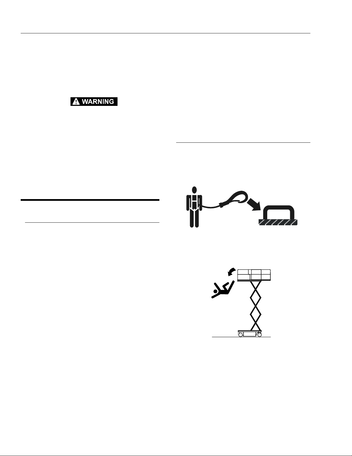
• JLG Industries, Inc. recommends that all persons in the
platform wear a full body harness with a lanyard
attached to an authorized lanyard anchorage point
while operating this machine. For further information
regarding fall protection requirements on JLG products, contact JLG Industries, Inc.
• Prior to operation, ensure all gates are fastened and
secured in their proper position. Identify the designated lanyard anchorage point(s) at the platform and
securely attach the lanyard. Attach only one (1) lanyard
per lanyard anchorage point.
• Keep both feet firmly positioned on the platform floor at
all times. Never position ladders, boxes, steps, planks,
or similar items on unit to provide additional reach for
any purpose.
• Never use the scissor arm assembly to gain access to
or leave the platform.
1-2 – JLG Lift – 3120854
Page 11
SECTION 1 - SAFETY PRECAUTIONS
• Use extreme caution when entering or leaving platform. Ensure that the scissor arm assembly is fully lowered. Face the machine when entering or leaving the
platform. Always maintain “three point contact” with
the machine, using two hands and one foot or two feet
and one hand at all times during entry and exit.
• Platform-to-structure transfers at elevated positions are
discouraged. Where transfer is necessary, enter/exit
through the gate only with the platform within 1 foot
(0.3m) of a safe and secure structure. 100% tie-off is
also required in this situation utilizing two lanyards.
One lanyard must be attached to the platform with the
second lanyard attached to the structure. The lanyard
connected to the platform must not be disconnected
until such time the transfer to the structure is safe and
complete.
• Keep oil, mud, and slippery substances cleaned from
footwear and the platform floor.
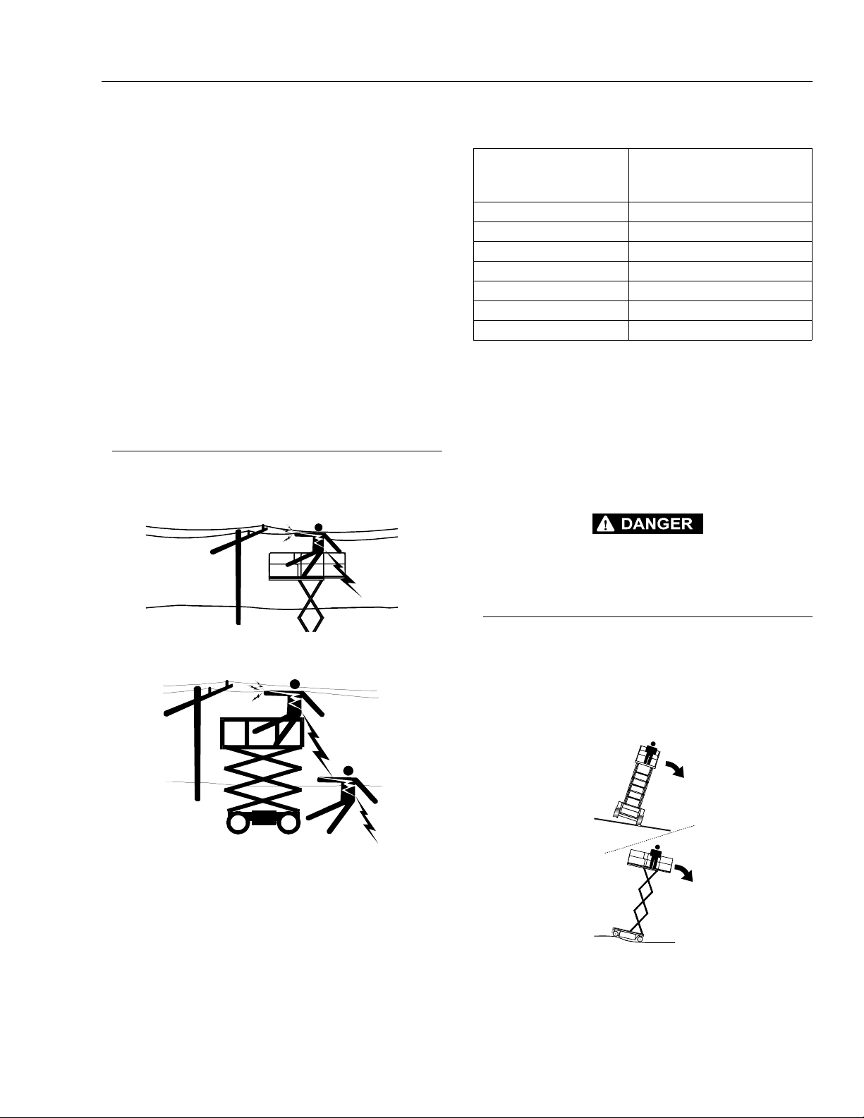
Electrocution Hazards
• This machine is not insulated and does not provide
protection from contact with an electrically charged
conductor.
Table 1-1.Minimum Safe Approach Distances (M.S.A.D.)
Voltage Range
(Phase to Phase)
0 to 300V AVOID CONTACT
Over 300V to 50 KV 10 (3)
Over 50KV to 200 KV 15 (5)
Over 200 KV to 350 KV 20 (6)
Over 350 KV to 500 KV 25 (8)
Over 500 KV to 750 KV 35 (11)
Over 750 KV to 1000 KV 45 (14)
NOTE: This requirement shall apply except where
employer, local or governmental regulations
are more stringent.
• Maintain a clearance of at least 10 ft. (3m) between any
part of the machine and its occupants, their tools, and
their equipment from any electrical line or apparatus
carrying up to 50,000 volts. One foot additional clearance is required for every additional 30,000 volts or
less.
MINIMUM SAFE APPROACH
DISTANCE
in Feet (Meters)
• Maintain safe clearance from electrical lines, apparatus, or any energized (exposed or insulated) parts in
accordance with the Minimum Safe Approach Distance
(MSAD) as specified in Table 1-1. Allow for machine
movement and electrical line swaying.
DO NOT MANEUVER MACHINE OR PERSONNEL INSIDE PROHIBITED ZONE (MSAD). ASSUME ALL ELECTRICAL PARTS AND WIRING ARE ENERGIZED UNLESS KNOWN OTHERWISE.
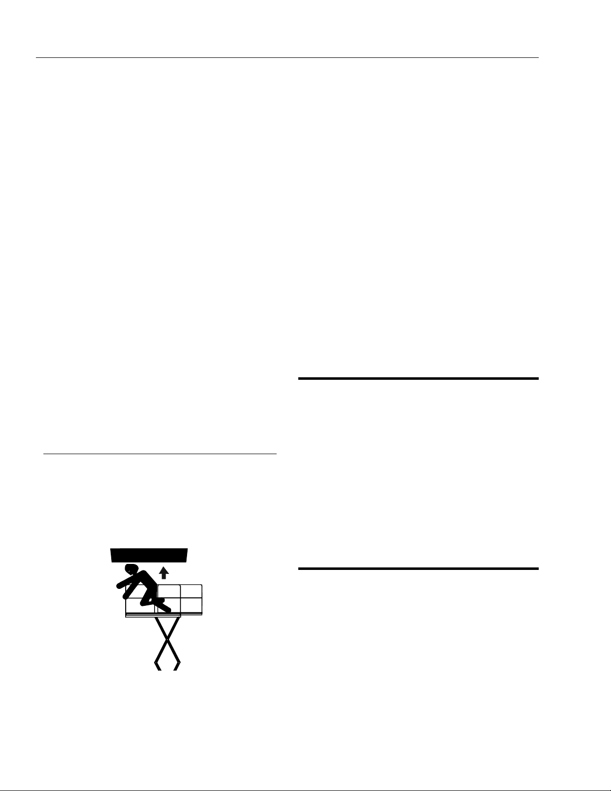
Tipping Hazards
• Ensure that the ground conditions are adequate to
support the maximum tire load indicated on the tire
load decals located on the chassis adjacent to each
wheel. Do not travel on unsupported surfaces.
• The user should be familiar with the driving surface
before driving. Do not exceed the allowable sideslope
and grade while driving.
Do not elevate platform or drive with platform elevated
while on or near a sloping, uneven, or soft surface.
Ensure machine is positioned on a firm, level and uniformly supported surface before elevating platform or
driving with the platform in the elevated position.
3120854 – JLG Lift – 1-3
Page 12
SECTION 1 - SAFETY PRECAUTIONS
• Before driving on floors, bridges, trucks, and other surfaces, check allowable capacity of the surfaces.
• Never exceed the maximum work load as specified on
the platform. Distribute loads evenly on platform floor.
Keep all loads within the confines of the platform,
unless authorized by JLG.
• Keep the chassis of the machine a minimum of 2 ft.
(0.6m) from holes, bumps, drop-offs, obstructions,
debris, concealed holes, and other potential hazards at
the ground level.
• Never attempt to use the machine as a crane. Do not
tie-off machine to any adjacent structure. Never attach
wire, cable, or any similar items to platform.
• Do not operate the machine when wind conditions
exceed 28 mph (12.5 m/s).Unless otherwise specified
on machine or accessory.
• Do not cover the platform sides or carry large surfacearea items in the platform when operating outdoors.
The addition of such items increases the exposed wind
area of the machine.
• Do not increase the platform size with unauthorized
deck extensions or attachments.
• If scissor arm assembly or platform is caught so that
one or more wheels are off the ground, all persons
must be removed before attempting to free the
machine. Use cranes, forklift trucks, or other appropriate equipment to stabilize machine and remove personnel.
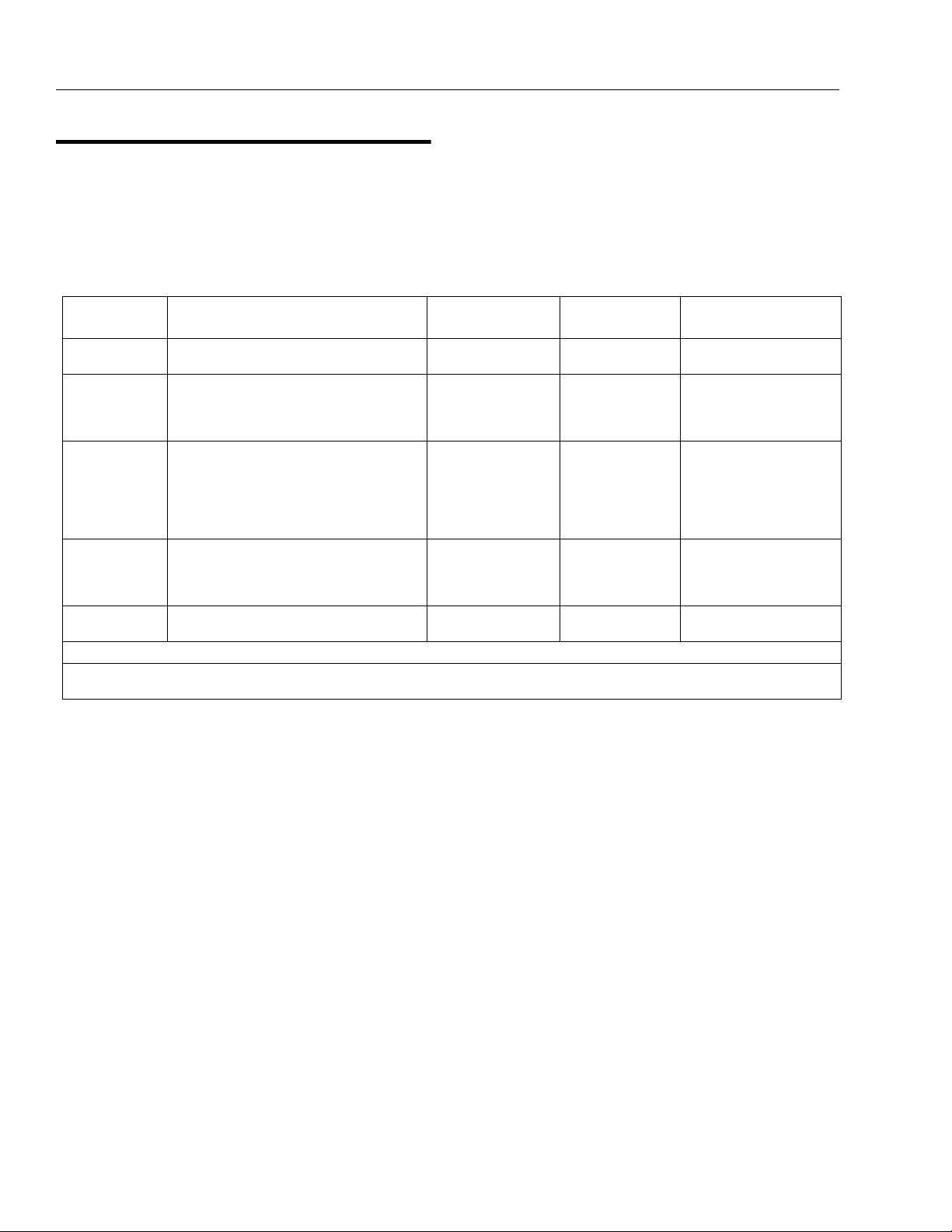
Crushing and Collision Hazards
• Approved head gear must be worn by all operating
and ground personnel.
• Keep hands and limbs out of the scissor arm assembly
during operation.
• Watch for obstructions around machine and overhead
when driving. Check clearances above, on sides, and
bottom of platform when lifting or lowering platform..
• Keep non-operating personnel at least 6 ft. (1.8m)
away from machine during all driving operations.
• Under all travel conditions, the operator must limit
travel speed according to conditions of ground surface, congestion, visibility, slope, location of personnel,
and other factors causing hazards of collision or injury
to personnel.
• Be aware of stopping distances in all drive speeds.
When driving in high speed, switch to low speed
before stopping. Travel grades in low speed only.
• Do not use high speed drive in restricted or close quarters or when driving in reverse.
• Exercise extreme caution at all times to prevent obstacles from striking or interfering with operating controls
and persons in the platform.
• Ensure that operators of other overhead and floor level
machines are aware of the aerial work platform’s presence. Disconnect power to overhead cranes. Barricade
floor area if necessary.
• Avoid operating over ground personnel. Warn personnel not to work, stand, or walk under a raised platform.
Position barricades on floor as necessary.
1.4 TOWING, LIFTING, AND HAULING
• Never allow personnel in platform while towing, lifting,
or hauling.
• This machine should not be towed, except in the event
of emergency, malfunction, power failure, or loading/
unloading. Refer to Section 6 for emergency towing
procedures.
• Ensure platform is fully retracted and completely
empty of tools prior to towing, lifting or hauling.
• When lifting machine with a forklift, position forks only
at designated areas of the machine. Lift with a forklift of
adequate capacity.
• Refer to Section 4 for lifting information.
1.5 ADDITIONAL HAZARDS / SAFETY
• Do not use machine as a ground for welding.
• When performing welding or metal cutting operations,
precautions must be taken to protect the chassis from
direct exposure to weld and metal cutting spatter.
• Do not refuel the machine with the engine running
(where applicable).
• During operation, keep all body parts inside platform
railing.
• Always post a lookout when driving in areas where
vision is obstructed.
1-4 – JLG Lift – 3120854
• Battery fluid is highly corrosive. Avoid contact with skin
and clothing at all times.
Charge batteries only in a well ventilated area.
Page 13

SECTION 2 - USER RESPONSIBILITIES, MACHINE PREPARATION, AND INSPECTION
SECTION 2. USER RESPONSIBILITIES, MACHINE PREPARATION, AND INSPECTION
2.1 PERSONNEL TRAINING
The aerial platform is a personnel handling device; so it is
necessary that it be operated and maintained only by
trained personnel.
Persons under the influence of drugs or alcohol or who
are subject to seizures, dizziness or loss of physical control must not operate this machine.
Operator Training
Operator training must cover:
1. Use and limitations of the controls in the platform
and at the ground, emergency controls and safety
systems.
2. Control labels, instructions, and warnings on the
machine.
3. Rules of the employer and government regulations.
4. Use of approved fall protection device.
5. Enough knowledge of the mechanical operation of
the machine to recognize a malfunction or potential
malfunction.
6. The safest means to operate the machine where
overhead obstructions, other moving equipment,
and obstacles, depressions, holes, drop-offs.
7. Means to avoid the hazards of unprotected electrical
conductors.
8. Specific job requirements or machine application.
Tra i nin g Sup er vis i on
Training must be done under the supervision of a qualified
person in an open area free of obstructions until the
trainee has developed the ability to safely control and
operate the machine.
Operator Responsibility
The operator must be instructed that he/she has the
responsibility and authority to shut down the machine in
case of a malfunction or other unsafe condition of either
the machine or the job site.
NOTE: The Manufacturer or Distributor will provide qualified
people for training assistance with the first unit(s)
delivered and from tha t time forwa rd as r equested b y
the user or his/her personnel.
3120854 – JLG Lift – 2-1
Page 14
SECTION 2 - USER RESPONSIBILITIES, MACHINE PREPARATION, AND INSPECTION
2.2 PREPARATION, INSPECTION, AND MAINTENANCE
The following table covers the periodic machine inspec-
maintenance must be increased as necessary when the
machine is used in a harsh or hostile environment, if the
machine is used with increased frequency, or if the
machine is used in a severe manner.
tions and maintenance recommended by JLG Industries,
Inc. Consult local regulations for further requirements for
aerial work platforms. The frequency of inspections and
Table 2-1.Inspection and Maintenance Table
Type Frequency
Pre-Start
Inspection
Pre-Delivery
Inspection
(See Note)
Frequent
Inspection
Annual
Machine
Inspection
Preventative
Maintenance
Before using each day; or
whenever there’s an Operator change.
Before each sale, lease, or rental delivery. Owner, Deale r, or
In service for 3 months or 150 hours,
whichever comes first; or
Out of service for a period of more than 3
months; or
Purchased used.
Annually, no later than 13 months from the
date of prior inspection.
At intervals as specified in the Service and
Maintenance Manual.
Primary
Responsibility
User or Operator User or Operator Op e r a t o r an d Sa f e t y
User
Owner, Dealer, or
User
Owner, Dealer, or
User
Owner, Dealer, or
User
Service
Qualification
Qualified JLG
Mechanic
Qualified JLG
Mechanic
Factory-Certified
Service Technician*
Qualified JLG
Mechanic
Reference
Manual
Service and Maintenance Manual and applicable JLG inspection
form
Service and Maintenance Manual and applicable JLG inspection
form
Service and Maintenance Manual and applicable JLG inspection
form
Service and Maintenance Manual
NOTE: Inspection forms are available from JLG. Use the Service and Maintenance Manual to perform inspections.
* JLG Industries, Inc. recognizes a Factory-Certified Service Technician as a person who has successfully completed the JLG Service
Training School for the specific JLG product model.
2-2 – JLG Lift – 3120854
Page 15

SECTION 2 - USER RESPONSIBILITIES, MACHINE PREPARATION, AND INSPECTION
Pre-Start Inspection
The Pre-Start Inspection should include each of the following:
1. Cleanliness – Check all surfaces for leakage (oil,
fuel, or battery fluid) or foreign objects. Report any
leakage to the proper maintenance personnel.
2. Decals and Placards – Check all for cleanliness
and legibility. Make sure none of the decals and
placards are missing. Make sure all illegible decals
and placards are cleaned or replaced.
3. Operators and Safety Manuals – Make sure a copy
of the Operator and Safety Manual, EMI Safety Manual (Domestic only), and ANSI Manual of Responsibilities (Domestic only) is enclosed in the weather
resistant storage container.
4. “Walk-Around” Inspection – Refer to Figures 1 and
2.
5. Battery – Charge as required.
6. Fuel (Combustion Engine Powered Machines) –
Add the proper fuel as necessary.
7. Hydraulic Oil – Check the hydraulic oil level. Ensure
hydraulic oil is added as required.
8. Function Check – Once the “Walk-Around” Inspec-
tion is complete, perform a functional check of all
systems in an area free of overhead and ground
level obstructions. Refer to Section 4 for more specific instructions.
Function Check
Perform the Function Check as follows:
1. From the ground control panel with no load in the
platform:
a. Check that all guards protecting the switches or
locks are in place;
b. Operate all functions and check all limiting and
cut-out switches; See Table 2-2, Maximum Cutout Height
c. Check auxiliary power (or manual descent);
d. Ensure that all machine functions are disabled
when the Emergency Stop Button is activated.
Table 2-2. Maximum Cutout Height
Model
1932E2 2.6 m N/A
2032E2 2.1 m N/A
2632E2
(Australian Only)
2632E2/2646E2 2.6 m N/A
3246E2 2.8 m N/A
High Drive Cutout
(Maximum Height)
2.9 m N/A
Drive Cutout
IF THE MACHINE DOES NOT OPERATE PROPERLY, TURN OFF
THE MACHINE IMMEDIATELY! REPORT THE PROBLEM TO THE
PROPER MAINTENANCE PERSONNEL. DO NOT OPERATE THE
MACHINE UNTIL IT IS DECLARED SAFE FOR OPERATION.
2. From the platform control console:
a. Ensure that the control console is firmly secured
in the proper location;
b. Check that all guards protecting the switches or
locks are in place;
c. Operate all functions and check all limiting and
cut-out switches;
d. Ensure that all machine functions are disabled
when the Emergency Stop Button is pushed in.
3. With the platform in the transport (stowed) position:
a. Drive the machine on a grade, not to exceed the
rated gradeability, and stop to ensure the brakes
hold;
Check the tilt sensor alarm to ensure proper operation.
3120854 – JLG Lift – 2-3
Page 16

SECTION 2 - USER RESPONSIBILITIES, MACHINE PREPARATION, AND INSPECTION
192120
2425262728
29 3031
32
333435
10
11
12
4
3
2
1
5
6
7
8
9
13
14
15
16
17
18
22
Figure 2-1. Daily Walk-Around Inspection - 2032E2/2632E2/2646E2/3246E2 (Sheet 1 of 2).
23
2-4 – JLG Lift – 3120854
Page 17

SECTION 2 - USER RESPONSIBILITIES, MACHINE PREPARATION, AND INSPECTION
GENERAL
Begin the “Walk-Around Inspection” at Item 1, as noted
on the diagram. Continue Left (counterclockwise viewed
from top) checking each item in sequence for the conditions listed in the following checklist.
TO AVOID POSSIBLE INJURY, BE SURE MACHINE POWER IS
“OFF” DURING “WALK-AROUND INSPECTION”.
DO NOT OVERLOOK VISUAL INSPECTION OF CHASSIS UNDERSIDE. CHECKING THIS AREA OFTEN RESULTS IN DISCOVERY
OF CONDITIONS WHICH COULD CAUSE EXTENSIVE MACHINE
DAMAGE.
NOTE: On each item, make sure there are no loose or
missing parts, that they are securely fastened, and
that no visible damage exists in addition to any
other criteria mentioned.
1. Platform Control Console - Placard secure and
legible, control lever and switches return to neutral, control lever lock and emergency stop switch
function properly, manual in storage box.
2. Spindle, Tie Rod and Steer Linkage (left front) See Note
3. Safety Prop - See Note
4. Sizzor Arms and Sliding Wear Pads - See Note
5. Wheel and Tire Assembly, Left Front - See Note
6. Drive Cutout Switch - See Note
7. Compartment Cover and Latches - See Note
8. Ground Controls - Placard secure and legible,
control switches return to neutral position, emergency stop switch functions properly. Control
markings legible.
9. Hydraulic Reservoir - Recommended hydraulic
fluid level on level indicator on tank. Breather cap
secure and working.
10. Hydraulic Filter - See Note
11. Hydraulic Pump/Motor - See Note
12. Pothole Protection System - See Note
13. Hourmeter - See Note
14. Wire Installation - See Note
15. Control Valve Installation - No unsupported wires
or hoses; no damaged or broken wires.
16. Wheel and Tire Assembly, Left Rear - See Note
17. Drive Motor, Left Rear - See Note
18. Sizzor Arms and Sliding Wear Pads - See Note
19. Handle for Manual Descent (2646E2/3246E2) See Note
20. Manual Descent Pump (2632E2/2646E2/3246E2) See Note
21. Manual Descent (2032E2) - See Note
22. Brake Cylinder - See Note
23. Ladder - See Note
24. Sizzor Arms and Sliding Wear Pads - See Note
25. Drive Motor, Right Rear - See Note
26. Wheel and Tire Assembly, Right Rear - See Note
27. Lift Cylinder - See Note
28. Tilt Switch - See Note
29. Battery Compartment - Proper electrolyte level.
30. Pothole Protection System - See Note
31. Battery Charger - See Note
32. Compartment Cover and Latches - See Note
33. Wheel and Tire Assembly, Right Front - See Note
34. Platform/Handrail Installation (Not Shown) - See
Note
35. Sizzor Arms and Sliding Wear Pads - See Note
Figure 2-1. Daily Walk-Around Inspection - 2032E2/2632E2/2646E2/3246E2 (Sheet 2 of 2).
3120854 – JLG Lift – 2-5
Page 18

SECTION 2 - USER RESPONSIBILITIES, MACHINE PREPARATION, AND INSPECTION
21
22
33
32
11
12
13
14
6
7
8
9
10
4
3
2
1
5
31
30
29
28
27
26
15
25
24
23
16
17
Figure 2-2. Daily Walk-Around Inspection - 1932E2 (Sheet 1 of 2).
2-6 – JLG Lift – 3120854
18 19
20
Page 19

SECTION 2 - USER RESPONSIBILITIES, MACHINE PREPARATION, AND INSPECTION
GENERAL
Begin the “Walk-Around Inspection” at Item 1, as noted
on the diagram. Continue Left (counterclockwise viewed
from top) checking each item in sequence for the conditions listed in the following checklist.
TO AVOID POSSIBLE INJURY, BE SURE MACHINE POWER IS
“OFF” DURING “WALK-AROUND INSPECTION”.
DO NOT OVERLOOK VISUAL INSPECTION OF CHASSIS UNDERSIDE. CHECKING THIS AREA OFTEN RESULTS IN DISCOVERY
OF CONDITIONS WHICH COULD CAUSE EXTENSIVE MACHINE
DAMAGE.
NOTE: On each item, make sure there are no loose or
missing parts, that they are securely fastened, and
that no visible damage exists in addition to any
other criteria mentioned.
1. Platform Control Console - Placard secure and legible, control lever and switches return to neutral,
control lever lock and emergency stop switch function properly, manual in storage box.
2. Spindle, Tie Rod and Steer Linkage (left front) - See
Note
3. Safety Prop - See Note
4. Sizzor Arms and Sliding Wear Pads - See Note
5. Drive Motor, Left Front - See Note
6. Wheel and Tire Assembly, Left Front - See Note
7. Drive Cutout Switch - See Note
8. Compartment Cover and Latches - See Note
9. Ground Controls - Placard secure and legible, control switches return to neutral position, emergency
stop switch functions properly. Control markings
legible.
10. Hydraulic Reservoir - Recommended hydraulic
fluid level on level indicator on tank. Breather cap
secure and working.
11. Hydraulic Filter - See Note
12. Hydraulic Pump/Motor - See Note
13. Pothole Protection System - See Note
14. Hourmeter - See Note
15. Wire Installation - See Note
16. Wheel and Tire Assembly, Left Rear - See Note
17. Sizzor Arms and Sliding Wear Pads - See Note
18. Manual Descent - See Note
19. Brake Cylinder - See Note
20. Ladder - See Note
21. Control Valve Installation - No unsupported wires or
hoses; no damaged or broken wires.
22. Sizzor Arms and Sliding Wear Pads - See Note
23. Wheel and Tire Assembly, Right Rear - See Note
24. Lift Cylinder - See Note
25. Tilt Switch - See Note
26. Battery Compartment - Proper electrolyte level
27. Pothole Protection System - See Note
28. Battery Charger - See Note
29. Compartment Cover and Latches - See Note
30. Wheel and Tire Assembly, Right Front - See Note
31. Drive Motor, Right Rear - See Note
32. Platform/Handrail Installation (Not Shown) - See
Note
33. Sizzor Arms and Sliding Wear Pads - See Note
Figure 2-2. Daily Walk-Around Inspection - 1932E2 (Sheet 2 of 2).
3120854 – JLG Lift – 2-7
Page 20

SECTION 2 - USER RESPONSIBILITIES, MACHINE PREPARATION, AND INSPECTION
This page left blank intentionally.
2-8 – JLG Lift – 3120854
Page 21

SECTION 3 - USER RESPONSIBILITIES AND MACHINE CONTROL
SECTION 3. USER RESPONSIBILITIES AND MACHINE CONTROL
3.1 GENERAL
SINCE THE MANUFACTURER HAS NO DIRECT CONTROL OVER
MACHINE APPLICATION AND OPERATION, CONFORMANCE WITH
GOOD SAFETY PRACTICES IN THESE AREAS IS THE RESPONSIBILITY OF THE USER AND HIS OPERATING PERSONNEL.
This section provides the necessary information needed
to understand control functions. Included in this section
are the operating characteristics and limitations, and functions and purposes of controls and indicators. It is important that the user read and understand the proper
procedures before operating the machine. These procedures will aid in obtaining optimum service life and safe
operation.
3.2 PERSONNEL TRAINING
The scissor lift is a personnel handling device; therefore, it
is essential that it be operated and maintained only by
authorized and qualified personnel who have demonstrated that they understand the proper use and maintenance of the machine. It is important that all personnel
who are assigned to and responsible for the operation
and maintenance of the machine undergo a thorough
training program and check out period in order to become
familiar with the characteristics prior to operating the
machine.
Persons under the influence of drugs or alcohol or who
are subject to seizures, dizziness or loss of physical control must not be permitted to operate the machine.
Operator Training
Operator training must include instruction in the following:
1. Use and limitations of the platform controls, ground
controls, emergency controls and safety systems.
2. Knowledge and understanding of this manual and of
the control markings, instructions and warnings on
the machine itself.
3. Knowledge and understanding of all safety work
rules of the employer and of Federal, State and
Local Statutes, including training in the recognition
and avoidance of potential hazards in the work
place; with particular attention to the work to be performed.
4. Proper use of all required personnel safety equipment.
5. Sufficient knowledge of the mechanical operation of
the machine to recognize a malfunction or potential
malfunction.
6. The safest means to operate near overhead obstructions, other moving equipment, obstacles, depressions, holes, dropoffs, etc. on the supporting
surface.
7. Means to avoid the hazards of unprotected electrical
conductors.
8. Any other requirements of a specific job or machine
application.
Tra i nin g Sup er vis i on
Training must be done under the supervision of a qualified
operator or supervisor in an open area free of obstructions
until the trainee has developed the ability to safely control
a scissor lift in congested work locations.
Operator Responsibility
The operator must be instructed that he has the responsibility and authority to shut down the machine in case of a
malfunction or other unsafe condition of either the
machine or the job site and to request further information
from his supervisor or JLG Distributor before proceeding.
NOTE: Manufacturer or Distributor will provide qualified per-
sons for training assistan ce with first uni t(s) delivered
and thereafter as requested by user or his personnel.
3.3 OPERATING CHARACTERISTICS AND LIMITATIONS
General
A thorough knowledge of the operating characteristics
and limitations of the machine is always the first requirement for any user, regardless of user’s experience with
similar types of equipment.
Placards
Important points to remember during operation are provided at the control stations by DANGER, WARNING,
CAUTION, IMPORTANT and INSTRUCTION placards. This
information is placed at various locations for the express
purpose of alerting personnel of potential hazards constituted by the operating characteristics and load limitations
of the machine. See foreword for definitions of the above
placards.
3120854 – JLG Lift – 3-1
Page 22

SECTION 3 - USER RESPONSIBILITIES AND MACHINE CONTROL
Capacities
Raising platform with or without any load in platform,
is based on the following criteria:
1. Machine is positioned on a smooth, firm and level
surface.
2. Load is within manufacturer’s rated capacity.
3. All machine systems are functioning properly.
Stability
This machine, as originally manufactured by JLG and
operated within its rated capacity on a smooth, firm and
level supporting surface, provides a stable aerial platform
for all platform positions.
3.4 CONTROLS AND INDICATORS FOR NON PROPORTIONAL CONTROL
Battery Charger
NOTE: If batteries are run down to under 6 volts, the sup-
plied battery charger will not pick up the charge.
The battery charger is located in the right side battery
door. The charger is a 20 Amp, SCR-style charger
equipped with a manual switch that allows the operator to
select 110-125 Volt input or 220-250 Volt input. A rocker
switch circuit breaker is included to reset the charger in
the event of a loss of power. LED’s on the front panel of
the charger indicate the status of charger operation
(Charge Complete, 80% Charge, Incomplete Charge,
Charger On, Abnormal Cycle)
Ground Control Station
DO NOT OPERATE FROM GROUND CONTROL STATION WITH
PERSONNEL IN THE PLATFORM EXCEPT IN AN EMERGENCY.
PERFORM AS MANY PRE-OPERATIONAL CHECKS AND INSPECTIONS FROM THE GROUND CONTROL STATION AS POSSIBLE.
REFER TO SECTION 2 FOR PRE-OPERATIONAL CHECKS AND
INSPECTIONS.
.
Figure 3-1. Ground Control Station
3-2 – JLG Lift – 3120854
Page 23

SECTION 3 - USER RESPONSIBILITIES AND MACHINE CONTROL
1. Power Selector Switch
A three position, key-operated power selector switch
supplies operating power to the platform or ground
controls, as selected. When positioned to platform,
the switch provides power to the emergency stop
switch at the platform controls. When positioned to
ground, the switch provides power to the emergency stop switch at the ground controls. With the
power selector switch in the center off position,
power is shut off to both platform and ground controls.
NOTE: With the power selector switch in the off position, the
key can be removed in order to avoid unauthorized
use of the machine.
Low speed is the de fault s peed fo r all fun ction s when
the platform is fully lowered. When the platform is
elevated, all functions operate in creep speed only.
2. Emergency Stop Switch
A two-position, red, mushroom-shaped emergency
stop switch, when positioned to on (pulled out) with
the power selector switch positioned to ground, furnishes operating power to the ground control station. In addition, the switch can be used to turn off
power to the function controls in the event of an
emergency. Power is turned on by pulling the switch
out (on), and is turned off by pushing the switch in
(off).
3. Lift Switch
A three-position, momentary-contact switch provides raising and lowering of the platform when
positioned to up or down.
2. Enable Switch
The enable switch is located on the left side
of the platform control box. This switch must be
depressed and held before and during actuation of
the lift function and for the duration of lift. The enable
switch works in conjunction with the lift switch.
3. Drive
The joystick is used to drive the machine forward
and reverse. To drive, the red trigger on the front of
the joystick must be depressed and held. Then the
joystick must be pushed forward for forward travel or
pulled backward for reverse travel. The adjustment
between low and high speed is determined by the
joystick travel. When motor is first activated you are
in low speed, high speed is achieved by moving the
joystick to the complete forward position.
NOTE: When the machine is raised, and a door is opened,
the machine will not drive.
The drive system may make an occ asion al cav itatio n
noise when driving with steer wheels turned all the
way in one direction or while going down hill. This
noise is a byproduct of the drive system.
4. Lift
The lift switch, when used in conjunction with the
enable switch, will raise or lower the machine. Lift is
activated by pressing and holding the enable and
moving the lift switch forward (lift up) or backward
(lift down).
4. Circuit Breaker
A push button reset 15 Amp circuit breaker, located
behind the pump/motor in the left side door, returns
interrupted power to the machine functions when
depressed.
5. Hourmeter
The machine may be equipped with an hourmeter to
indicate the number of hours the machine has been
operated. The hourmeter operates when a machine
function is operating or when key switch and emergency stop switch are on.
Platform Control Station
1. Emergency Stop Switch
A two-position, red, mushroom-shaped emergency
stop switch functions to provide power to the platform control station and also to turn off power to the
platform function controls in the event of an emergency. With the power selector switch positioned to
platform, power is turned on by pulling the switch
out (on), and is turned off by pushing the switch in
(off).
DO NOT “LIFT DOWN” WITHOUT COMPLETELY RETRACTING
THE PLATFORM EXTENSION.
5. Steer Switch
The thumb-operated steer switch, located on top of
the joystick controller, activates the steer wheels in
the direction the switch is moved (left or right).
DO NOT USE HIGH DRIVE SPEED WHEN DRIVING IN CLOSE
QUARTERS OR WHEN DRIVING IN REVERSE.
6. Drive Speed Select Switch
The speed select switch is a toggle switch which
allows you to select high or low speed.
NOTE: The High Drive Speed switch will cut-out when the
platform is raised above the stowed position, returning drive speed to low until the platform is lowered
completely.
3120854 – JLG Lift – 3-3
Page 24

SECTION 3 - USER RESPONSIBILITIES AND MACHINE CONTROL
Figure 3-2. Platform Control Station - Non Proportional Control
DO NOT OPERATE MACHINE IF HIGH DRIVE SPEED OPERATES
WHEN PLATFORM IS RAISED ABOVE THE STOWED POSITION.
NOTE: The machine is equipped with a Pothole Protection
System which lowers automatically when the platform is raised. The Pothole Protection System will
also lower when either of the door s are opene d, but
only on the side of the opened door and this will not
provide tip over protect ion. If the Poth ole Protect ion
System does not fully lower, the DRIVE function is
cut out until the platform is completely lowered.
7. Tilt Alarm Warning Horn.(If Equipped)
The Tilt Alarm Warning is activated by the Tilt Alarm
Switch when the chassis is on a slope. See Figure 31, Tilt, for degree of tilt per model.
Ta b le 3 - 1 . T i lt
1932E2/2032E2 2632E2/2646E2/3246E2
IF TILT ALARM IS ON WHEN PLATFORM IS RAISED, LOWER
PLATFORM COMPLETELY, THEN REPOSITION MACHINE SO
THAT IT IS LEVEL BEFORE RAISING PLATFORM.
8. Tilt Alarm Warning Light. (If Equipped)
A red warning light on the control box panel will illuminate when the chassis is on a slope. See Figure 31, Tilt, for degree of tilt per model
9. Horn. (If Equipped)
This push button switch, when activated, permits the
operator to warn jobsite personnel when the
machine is operating in the area.
10. Battery Discharge Indicator
The battery discharge indicator is a gauge that provides a visual indication of the condition of the batteries.
1.5 Degrees 2 Degrees
3-4 – JLG Lift – 3120854
Page 25

SECTION 3 - USER RESPONSIBILITIES AND MACHINE CONTROL
Figure 3-3. Platform Control Station - Proportional Control
3.5 CONTROLS AND INDICATORS FOR PROPORTIONAL CONTROL
The machine is equipped with control panels that use
symbols instead of words to indicate control functions.
Refer to Symbols figure for these symbols and their corresponding functions.
JLG SMART™ System
The machine is controlled by the JLG SMART™ System, a
24 volt, multiplex motor controller which works in conjunction with a joystick and several switches to operate all
machine functions.
Special operating characteristics of the JLG SMART™
System are noted where applicable. Special attention
should be paid to these operating characteristics, as they
may be somewhat different from those on previous JLG
machines.
IT IS A GOOD PRACTICE TO AVOID PRESSURE-WASHING ELECTRICAL/ELECTRONIC COMPONENTS. SHOULD PRESSUREWASHING BE UTILIZED TO WASH AREAS CONTAINING ELECTRICAL/ELECTRONIC COMPONENTS, JLG INDUSTRIES, INC. RECOMMENDS A MAXIMUM PRESSURE OF 750 PSI (52 BAR) AT A
MINIMUM DISTANCE OF 12 INCHES (30.5 CM) AWAY FROM THESE
COMPONENTS. IF ELECTRICAL/ELECTRONIC COMPONENTS
ARE SPRAYED, SPRAYING MUST NOT BE DIRECT AND BE FOR
BRIEF TIME PERIODS TO AVOID HEAVY SATURATION.
Ground Control Station
NOTE: Refer to the Ground Control Station for Non Propor-
tional Control machines.
3120854 – JLG Lift – 3-5
Page 26

SECTION 3 - USER RESPONSIBILITIES AND MACHINE CONTROL
Platform Control Station
1. Emergency Stop Switch - A two-position, red,
mushroom-shaped emergency stop switch functions to provide power to the platform control station
and also to turn off power to the platform function
controls in the event of an emergency. With the
power selector switch positioned to platform, power
is turned on by pulling the switch out (on), and is
turned off by pushing the switch in (off). Turning the
emergency stop switch off and then on again will
reset the smart system if a system fault has occurred
and the machine has shut down.
2. Membrane Switch Panel - The function switches at
the platform control station are an integral part of a
membrane switch panel, which contains switches
for drive, high drive, lift, powered deck extension (if
equipped), and posi-trac, plus a red tilt indicator
light (if equipped). The drive, lift and powered deck
extension function switches have a small green light
indicator beside them which is illuminated when that
function is active. The function switch light indicators
will flash once or twice, then go out, when the platform emergency stop switch is turned on. If the light
indicators fail to flash or if they fail to stop flashing,
re-cycle the emergency stop switch. To activate the
drive, lift, and powered deck functions, press the
applicable function switch, then activate the joystick
within three seconds to operate the function. If the
joystick is not activated within three seconds, power
is turned off to the function switch and the switch
must be pressed again. The posi-trac and high drive
functions are used in conjunction with the drive function. Do not try to operate the drive, lift, and powered
deck extension functions simultaneously. If the drive,
lift, and powered deck extension functions are
selected simultaneously, no function will operate. If
this occurs, pause, then press only one of the function switches to activate the function. Refer to the following paragraphs for more information about the
function switches.
3. Controller (Joystick) - The joystick controls three
functions: speed, direction, and powered deck
extension (if equipped). The joystick is used in conjunction with the trigger switch and controls the
drive, high drive, lift, and powered deck extension
switches to control speed and direction for the
selected function. The drive, high drive and posi-trac
functions may be operated simultaneously, but the
drive, lift, and powered deck extension functions
must be operated independently of each other. If the
drive, lift, and powered deck extension functions are
selected simultaneously, no function will operate. If
this occurs, pause, then press only one of the function switches to activate the function. To operate the
joystick, squeeze the red trigger switch, then position the joystick to forward or reverse, as desired
5. Steer Switch - The thumb-operated steer switch,
located on top of the joystick, works in conjunction
with the trigger switch and activates the steer wheels
in the direction the switch is moved (left or right).
6. Drive Switch - The drive switch, when used in con-
junction with the joystick, provides for driving the
machine in forward or reverse. Drive is activated by
pressing the drive switch, in conjunction with the
trigger switch, and moving the joystick forward (forward) or backward (reverse). Drive speed is determined by the distance the joystick is moved forward
or backward. Increased drive speed is possible
when the high drive speed switch is pressed either
simultaneously with the drive switch or while operating the drive function. The drive switch is part of the
enable circuit, which provides power to the joystick
and the drive function for 3 seconds when the drive
switch is pressed. If the joystick is not activated
within 3 seconds, the drive switch must be pressed
again before activating the joystick. When the joystick is returned to the center off position, the operator has 3 seconds to re-activate the joystick or select
another function before power is removed by the
enable circuit. In addition, the posi-trac switch can
be engaged while operating the drive function to
give a more evenly distributed oil flow to each drive
motor. Do not try to operate the drive, lift, and powered deck extension functions simultaneously. If the
drive, lift, and powered deck extension functions are
selected simultaneously, no function will operate. If
this occurs, pause, then press only one of the function switches to activate the function
NOTE: The machine is equipped with a Pothole Protection
System which lowers automatically when the platform is raised. If the Pothole Prot ect ion S ystem doe s
not fully lower, the DRIVE function is cut out until the
platform is completely lowered.
3-6 – JLG Lift – 3120854
Page 27

SECTION 3 - USER RESPONSIBILITIES AND MACHINE CONTROL
7. High Drive Speed Switch - The high drive speed
switch, when used in conjunction with the joystick
being operated in the drive mode, provides additional oil flow to the drive circuit for increased travel
speed. To operate high drive, depress the high drive
speed switch either simultaneously with the drive
switch or while operating the drive function.
DO NOT USE HIGH DRIVE SPEED WHEN DRIVING IN
CLOSE QUARTERS OR WHEN DRIVING IN REVERSE.
IF HIGH DRIVE IS SELECTED WHEN OIL TEMPERATURE IS VERY COLD (BELOW 4°C 40° F.) HIGH DRIVE
WILL NOT ENGAGE IMMEDIATELY. AS OIL WARMS
(ABOVE 4°C 40° F.) IF HIGH DRIVE IS SELECTED, IT
WILL ENGAGE AUTOMATICALLY WHILE DRIVING.
NOTE: The High Drive Speed switch will cut-out when the
platform is raised above the stowed position, returning drive speed to low until the platform is lowered
completely.
DO NOT ATTEMPT TO OPERATE THE LIFT AND DRIVE FUNCTIONS AT THE SAME TIME; NO FUNCTION WILL OPERATE AND IT
WILL BE NECESSARY TO RE-SELECT A SINGLE FUNCTION.
WHEN OPERATING LIFT DOWN MOVE THE JOYSTICK TO THE
FULL DOWN (FULLY BACKWARD) POSITION.
9. Positive Traction (Posi-Trac) Switch - This switch,
when pressed, activates a solenoid on the main control valve, forcing oil through a flow divider in the
drive circuit, maintaining hydraulic oil flow to both
drive motors for improved traction. The positive traction (Posi-trac) switch activates the positive traction
solenoid for a preset time when the positive traction
(Posi-trac) switch is pressed. Positive traction is
automatically de-activated after the preset time is
out. This function will only operate when the drive
function is activated.
10. Tilt Alarm Warning Horn (If Equipped) - The Tilt
Alarm Warning Horn is activated by the Tilt Alarm
Switch when the chassis is on a slope. (See Figure
3-1, Tilt for the appropriate degree of tilt). When the
machine is equipped with a powered deck extension, the horn is activated when the deck extension
is being extended or retracted.
DO NOT OPERATE MACHINE IF HIGH DRIVE SPEED OPERATES
WHEN PLATFORM IS RAISED ABOVE THE STOWED POSITION.
8. Lift Switch - The lift switch, when used in conjunc-
tion with the joystick, provides for raising and lowering the platform. Lift is activated by pressing the lift
switch and moving the joystick forward (lift up) or
backward (lift down). Lift up speed is determined by
the distance the joystick is moved forward. Lift down
speed is non-adjustable, and lift down is attained by
moving the joystick fully backward. The lift switch is
part of the enable circuit, which provides power to
the joystick and the lift function for 3 seconds when
the lift switch is pressed. If the joystick is not activated within 3 seconds, the lift switch must be
pressed again before activating the joystick. When
the joystick is returned to the center off position, the
operator has 3 seconds to re-activate the joystick or
select another function before power is removed by
the enable circuit. Do not try to operate the drive, lift,
and powered deck extension functions simultaneously. If the drive, lift, and powered deck extension functions are selected simultaneously, no
function will operate. If this occurs, pause, then
press only one of the function switches to activate
the function.
IF TILT ALARM IS ON WHEN PLATFORM IS RAISED, LOWER
PLATFORM COMPLETELY, THEN REPOSITION MACHINE SO
THAT IT IS LEVEL BEFORE RAISING PLATFORM.
11. Tilt Alarm Warning Light (Red) (If Equipped) - A
warning light on the membrane switch panel that
illuminates when the chassis is on a severe slope
(See Figure 3-1, Tilt for the appropriate degree of
tilt).
12. Horn (If Equipped) - This push-button switch, when
activated, permits the operator to warn jobsite personnel when the machine is operating in the area.
13. Battery Discharge Indicator (If Equipped) - The
battery discharge indicator is a gauge that provides
a visual indication of the condition of the batteries.
DO NOT LIFT DOWN WITHOUT COMPLETELY RETRACTING THE
PLATFORM EXTENSION.
3120854 – JLG Lift – 3-7
Page 28

SECTION 3 - USER RESPONSIBILITIES AND MACHINE CONTROL
1
1
3
2
3
2
Figure 3-4. Decal Location (1932E2)
3-8 – JLG Lift – 3120854
Page 29

SECTION 3 - USER RESPONSIBILITIES AND MACHINE CONTROL
Table 3-2. Decal Location Legend - 1932E2
Item #
1532E2/
1932E2
Ansi Australian
China/
English
Dutch French
French/
English
German Italian Japan
1 1702773 1702773 1702773 1702773 1702773 1702773 1702773 1702773 1702773
2 1703817 1703817 1703817 1703817 1703817 1703817 1703817 1703817 1703817
3 1703823 1703823 1704609 1703895 1703866 1703866 1703883 1703888 1703850
4 1703811 1703811 1703811 1703811 1703811 1703811 1703811 1703811 1703811
5 1704399 1704399 1704399 1704399 1704399 1704399 1704399 1704399 1704399
6 1703814 1703814 1703814 1703814 1703814 1703814 1703814 1703814 1703814
7 1703819 1703819 1703819 1703819 1703819 1703819 1703819 1703819 1703819
8 1703813 1703813 1704613 1703893 1703864 1703864 1703881 1703886 1703848
9 N/A N/A N/A 1702928 1702928 N/A 1702928 1702928 N/A
10 3252747
(1532E2)
3252598
(1932E2)
N/A
(1532E2)
3252598
(1932E2)
3252747
(1532E2)
3252598
(1932E2)
N/A
(1532E2)
3252598
(1932E2)
3252747
(1532E2)
3252598
(1932E2)
3252747
(1532E2)
3252598
(1932E2)
N/A
(1532E2)
3252598
(1932E2)
N/A
(1532E2)
3252598
(1932E2)
3252747
(1532E2)
3252598
(1932E2)
11 3251813 N/A N/A 3251813 N/A 3251813 N/A N/A N/A
12 N/A 1703969 N/A 1703973 1703970 1703868 1703971 1703972 N/A
13 1703818 1703818 1704611 1703894 1703865 1703865 1703882 1703887 1704282
14 1703869 1703869 1703869 1703869 1703869 1703869 1703869 1703869 1703869
15 1702153 1704123 1704607 N/A N/A 1703074 N/A N/A 1701621
16 1703868 N/A 1703868 N/A N/A 1703868 N/A 1703886 1703868
17 1703706 1703706 1703706 1703706 1703706 1703706 1703706 1703706 1703706
18 1703816 3252616 1704616 1704173 1704173 1703867 1704173 1704173 1704278
(1532E2)
1703868
(1932E2)
19 N/A 1703877 N/A 1703896 1703878 N/A 1703884 1703889 1704807
20 1701509 1701509 1701509 1701509 1701509 1701509 1701509 1701509 1701509
21 1704017 1704017 1704608 1704149 1704146 1704146 1704147 1704148 1704144
22 1703822 1703822 1703822 1703822 1703822 1703822 1703822 1703822 1703822
23 3252645 3252534 3252699 3252533 3252645
(1532E2)
3252533
(1932E2)
3252645 3252533 3252533 3252644
(1532E2)
3252749
(1932E2)
3120854 – JLG Lift – 3-9
Page 30

SECTION 3 - USER RESPONSIBILITIES AND MACHINE CONTROL
Table 3-3. Decal Location Legend - 1932E2 (continued)
Item #
1532E2/
1932E2
1 1702773 1702773 1702773 1702773 1702773
2 1703817 1703817 1703817 1703817 1703817
3 1703858 1703834 1703842 1703842 1703823
4 1703811 1703811 1703811 1703811 1703811
5 1704399 1704399 1704399 1704399 1704399
6 1703814 1703814 1703814 1703814 1703814
7 1703819 1703819 1703819 1703819 1703819
8 1703856 1703832 1703840 1703840 1703813
9 N/A N/A 1702928 N/A 1702928
10 3252747
11 N/A 3251813 N/A 3251813 N/A
12 N/A 1703829 1703974 1703837 1703969
13 1703857 1703865 1703841 1703841 1703818
14 1703869 1703869 1703869 1703869 1703869
15 1703962 1703961 N/A 1702552 N/A
16 1703868 1703868 N/A 1703868 N/A
17 1703706 1703706 1703706 1703706 1703706
18 1703859 1703835 1704173 1703843 1704173
19 1703868 1703868 1703897 1703868 1703877
20 1701509 1701509 1701509 1701509 1701509
21 1704145 1704142 1704143 1704143 1704017
22 1703822 1703822 1703822 1703822 1703822
23 3252645 3252645 3252533 3252645 3252533
Korean Brazil Spanish Latin CE/English
(1532E2)
3252598
(1932E2)
3252747
(1532E2)
3252598
(1932E2)
N/A
(1532E2)
3252598
(1932E2)
3252747
(1532E2)
3252598
(1932E2)
3252747
(1532E2)
3252598
(1932E2)
3-10 – JLG Lift – 3120854
Page 31

SECTION 3 - USER RESPONSIBILITIES AND MACHINE CONTROL
2
4
5
4
1
2
3
2
4
6
5
13
9
8
7
14
5
6
11
10
15
2
2
3
17
18
16
14
19
Figure 3-5. Decal Location - 2032E2/2632E2/2646E2
3120854 – JLG Lift – 3-11
Page 32

SECTION 3 - USER RESPONSIBILITIES AND MACHINE CONTROL
Table 3-4. Decal Location Legend - 2032E2/2632E2/2646E2
Item #
2032E2
2632E2
2646E2
1 1702773 1702773 1702773 1702773 1702773 1702773 1702773 1702773 1702773
2 1703817 1703817 1703817 1703817 1703817 1703817 1703817 1703817 1703817
3 1703823 1703823 1704069 1703895 1703866 1703842 1703883 1703888 1703850
4 1703811 1703811 1703811 1703811 1703811 1703811 1703811 1703811 1703811
5 1703814 1703814 1703814 1703814 1703814 1703814 1703814 1703814 1703814
6 1704400
7 1703812 1703812 1703812 1703812 1703812 1703812 1703812 1703812 1703812
8 1703706 1703706 1703706 1703706 1703706 1703706 1703706 1703706 1703706
9 1703818 1703818 1704611 1703894 1703865 1703841 1703882 1703887 1704282
10 3252567
11 N/A N/A N/A 1702928 N/A 1702928 1702928 1702928 N/A
12 1703813 1703813 1704613 1703893 1703864 1703840 1703881 1703886 1703848
13 1701509 1701509 1701509 1701509 1701509 1701509 1701509 1701509 1701509
14 1703816 1704115 1704616 1703898 1703867 1703898 1703898 1703898 1704807
15 1703821 1703969 1704610 1703973 1703861 1703874 1703971 1703972 1703845
16 1703694 1703877 1703694 1703896 1703694 1703897 1703884 1703889 1704283
17 1704420
18 1703698 1703698 1703614 1703892 N/A 1703839 1703880 1703885 1704281
19 1703822
20 1703621 1703621 1703621 1703621 1703621 1703621 1703621 1703621 1703621
21 1703697 1703697 1703697 1703697 1703697 1703697 1703697 1703697 1703697
22 3252645 3252534 3252699 3252565 3252564 3252565 3252565 3252565 3252749
23 N/A 1704123 1703694 N/A 1703694 N/A N/A N/A 1704283
24 N/A 1702153 1704607 N/A 1703074 N/A N/A N/A 1701621
Ansi Australian
(2032E2)
1704137
(2632E2)
1704402
(2646E2)
(2032E2)
1705013
(2632E2)
3252568
(2646E2)
(2632E2 only)
(2032E2 only)
(2632E2 only)
(2032E2 only)
1704400
(2032E2)
1704137
(2632E2)
1704402
(2646E2)
3252567
(2032E2)
1705013
(2632E2)
3252568
(2646E2)
1704420
1703822
China/
English
1704400
(2032E2)
N/A
(2632E2)
1704402
(2646E2)
3252567
(2032E2)
N/A
(2632E2)
3252568
(2646E2)
1704420
(2632E2 only)
1703822
(2032E2 only)
Dutch CSA/French Spanish German Italian Japan
1704400
(2032E2)
N/A
(2632E2)
1704402
(2646E2)
3252567
(2032E2)
N/A
(2632E2)
3252568
(2646E2)
1704420
(2632E2 only)
1703822
(2032E2 only)
1704400
(2032E2)
1704137
(2632E2)
1704402
(2646E2)
3252567
(2032E2)
1705013
(2632E2)
3252568
(2646E2)
1704420
(2632E2 only)
1703822
(2032E2 only)
1704400
(2032E2)
N/A
(2632E2)
1704402
(2646E2)
3252567
(2032E2)
N/A
(2632E2)
3252568
(2646E2)
1704420
(2632E2 only)
1703822
(2032E2 only)
1704400
(2032E2)
N/A
(2632E2)
1704402
(2646E2)
3252567
(2032E2)
N/A
(2632E2)
3252568
(2646E2)
1704420
(2632E2 only)
1703822
(2032E2 only)
1704400
(2032E2)
N/A
(2632E2)
1704402
(2646E2)
3252567
(2032E2)
N/A
(2632E2)
3252568
(2646E2)
1704420
(2632E2 only)
1703822
(2032E2 only)
(2632E2 only)
(2032E2 only)
1704400
(2032E2)
1704137
(2632E2)
1704402
(2646E2)
3252567
(2032E2)
1705013
(2632E2)
3252568
(2646E2)
(2032E2/
2646E2)
1703868
(2632E2)
1704420
1703822
3-12 – JLG Lift – 3120854
Page 33

SECTION 3 - USER RESPONSIBILITIES AND MACHINE CONTROL
Table 3-5. Decal Location Legend - 2032E2/2632E22646E2 (continued)
Item #
2032E2
2632E2
2646E2
1 1702773 1702773 1702773 1702773 1702773
2 1703817 1703817 1703817 1703817 1703817
3 1703842 170383 1703866 1703834 1703858
4 1703811 1703811 1703811 1703811 1703811
5 1703814 1703814 1703814 1703814 1703814
6 1704400
7 1703812 1703812 1703812 1703812 1703812
8 1703706 1703706 1703706 1703706 1703706
9 1703841 1703818 1703865 1703833 1703857
10 3252567
11 N/A 1702928 1702928 1702928 N/A
12 1703840 1703813 1703864 1703832 1703856
13 1701509 1701509 1701509 1701509 1701509
14 1703843 1703898 1703898 1703835 1703859
15 1703837 1703969 1703970 1703829 1703853
16 1703694 1703877 1703868 1703694 1703694
17 1704420
18 1703839 1703698 1703822 1703831 1703855
19 1703822
20 1702631 1702631 1702631 1703621 1703621
21 1703697 1703697 1703697 1703697 1703697
22 3252645 3252565 3252565 3252645 3252645
23 1703694 N/A N/A 1703694 1703694
24 1702552 N/A N/A 1703691 1703962
Latin CE/English CE/French Brazil Korean
(2032E2)
1704137
(2632E2)
1704402
(2646E2)
(2032E2)
1705013
(2632E2)
3252568
(2646E2)
(2632E2 only)
(2032E2 only)
1704400
(2032E2)
N/A
(2632E2)
1704402
(2646E2)
3252567
(2032E2)
N/A
(2632E2)
3252568
(2646E2)
1704420
(2632E2 only)
1703822
(2032E2 only)
1704400
(2032E2)
N/A
(2632E2)
1704402
(2646E2)
3252567
(2032E2)
N/A
(2632E2)
3252568
(2646E2)
1704420
(2632E2 only)
1703822
(2032E2 only)
1704400
(2032E2)
1704137
(2632E2)
1704402
(2646E2)
3252567
(2032E2)
1705013
(2632E2)
3252568
(2646E2)
1704420
(2632E2 only)
1703822
(2032E2 only)
1704400
(2032E2)
1704137
(2632E2)
1704402
(2646E2)
3252567
(2032E2)
1705013
(2632E2)
3252568
(2646E2)
1704420
(2632E2 only)
1703822
(2032E2 only)
3120854 – JLG Lift – 3-13
Page 34

SECTION 3 - USER RESPONSIBILITIES AND MACHINE CONTROL
16
17918
8
9
11
10
6
12
1
2
3
4
3
2
1
6
5
8
7
2
3
5
30
9
1
13
14
1
11
7
5
15
5
3
2
19
21
20
25
20
22
23
24
26
27
17
2
2
Figure 3-6. Decal Location - 3246E2
3-14 – JLG Lift – 3120854
Page 35

SECTION 3 - USER RESPONSIBILITIES AND MACHINE CONTROL
Table 3-6. Decal Location Legend - 3246E2
Item #
3246E2
1 1703817 1703817 1703817 1703817 1703817 1703817 1703817 1703817 1703817
2 1703811 1703811 1703811 1703811 1703811 1703811 1703811 1703811 1703811
3 1703814 1703814 1703814 1703814 1703814 1703814 1703814 1703814 1703814
4 1703823 1703842 1703850 1703866 1703842 1703823 1703866 1703883 1703888
5 1704403 1704403 1704403 1704403 1704403 1704403 1704403 1704403 1704403
6 1703819 1703819 1703819 1703819 1703819 1703819 1703819 1703819 1703819
7 3252619 3252619 3252619 3252619 3252619 3252619 3252619 3252619 3252619
8 1703813 1703840 1703848 1703864 1703840 1703813 1703864 1703881 1703886
9 1703818 1703841 1704282 1703865 1703841 1703818 1703865 1703882 1703887
10 3251813 3251813 N/A 3251813 N/A N/A N/A N/A N/A
11 1704277 1704277 1704277 1704277 1704277 1704277 1704277 1704277 1704277
12 1702631 1702631 1702631 1702631 1702631 1702631 1702631 1702631 1702631
13 1703823 1703842 1703850 1703866 1703842 1703823 1703866 1703883 1703888
14 3252645 3252645 3252749 3252645 3252565 3252565 3252565 3252565 3252565
15 1703812 1703812 1703812 1703812 1703812 1703812 1703812 1703812 1703812
16 1703706 1703706 1703706 1703706 1703706 1703706 1703706 1703706 1703706
17 1704201 1704201 1704282 1704201 N/A N/A N/A N/A N/A
18 1702153 1702552 1701621 1703064 N/A N/A N/A N/A N/A
19 1703697 1703697 1703697 1703697 1703697 1703697 1703697 1703697 1703697
20 1701509 1701509 1701509 1701509 1701509 1701509 1701509 1701509 1701509
21 1704201 1704201 1704201 1704201 N/A N/A N/A N/A N/A
22 1703821 1703837 1703845 1703861 N/A N/A N/A N/A N/A
23 1703695 1703838 1704280 1703862 N/A N/A N/A N/A N/A
24 1703816 1703843 1704807 1703867 N/A N/A N/A N/A N/A
25 N/A N/A N/A N/A 1704202 1704202 1704202 1704202 1704202
26 N/A N/A N/A N/A 1703974 1703969 1703970 1703971 1703972
27 N/A N/A N/A N/A 1703897 1703877 1703878 1703884 1703889
28 1704420 1704420 1704420 1704420 1704420 1704420 1704420 1704420 1704420
29 1703698 1703839 1704281 1703863 1703839 1703698 1703863 1703880 1703885
30 N/A N/A N/A N/A 1702928 N/A 1702928 N/A N/A
Ansi Latin Japan CSA/French CE/Spanish CE/English CE/French German Italian
3120854 – JLG Lift – 3-15
Page 36

SECTION 3 - USER RESPONSIBILITIES AND MACHINE CONTROL
Table 3-7. Decal Location Legend - 3246E2 (continued)
Item #
3246E2
1 1703817 1703817 1703817 1703817 1703817
2 1703811 1703811 1703811 1703811 1703811
3 1703814 1703814 1703814 1703814 1703814
4 1703823 1703834 1703858 1704609 1703895
5 1704403 1704403 1704403 1704403 1704403
6 1703819 1703819 1703819 1703819 1703819
7 3252619 3252619 3252619 3252619 3252619
8 1703813 1703832 1703856 1704613 1703893
9 1703818 1703833 1703857 1704611 1703894
10 N/A 3251813 N/A 3251813 N/A
11 1704277 1704277 1704277 1704277 1704277
12 1702631 1702631 1702631 1702631 1702631
13 1703823 1703834 1703858 1704609 1703895
14 3252534 3252645 3252645 3252699 3252565
15 1703812 1703812 1703812 1703812 1703812
16 1703706 1703706 1703706 1703706 1703706
17 1704133 1704201 1704201 1704201 N/A
18 1702153 1703961 1703962 1704607 N/A
19 1703697 1703697 1703697 1703697 1703697
20 1701509 1701509 1701509 1701509 1701509
21 N/A 1704201 1704201 1704201 N/A
22 N/A 1703820 1703853 1704610 N/A
23 N/A 1703830 1703854 1704615 N/A
24 N/A 1703835 1703859 1704616 N/A
25 1704203 N/A N/A N/A 1704202
26 1703969 N/A N/A N/A 1703973
27 1703877 N/A N/A N/A 1703896
28 1704420 1704420 1704420 1704420 1704420
29 1703698 1703831 1703855 1704614 1703892
30 N/A N/A N/A N/A 1702928
Australian Brazil Korean China Dutch
3-16 – JLG Lift – 3120854
Page 37

SECTION 4 - MACHINE OPERATION
SECTION 4. MACHINE OPERATION
4.1 DESCRIPTION
This machine is a self-propelled hydraulic lift equipped
with a work platform on an elevating scissor mechanism.
Vibrations emitted by these machines are not hazardous
to an operator in the work platform. The equivalent continuous A-Weighted sound pressure level at the work platform is less than 70 dB(A).
Table 4-1. Operating Specifications (CE and Australian)
MODEL 1932E2 2032E2 2632E2 (Aust Only) 2646E2 3246E2
Maximum Work Load (Ca pacity)
Extension Only:
Maximum Occupants
Extension Only
Maximum Travel Grade (Gradeab ility) 20% / 11.3 ° 25% / 14 ° 20% / 11.3 ° 25% / 14 ° 25% / 14 °
Maximum Travel Grade (Sidesl ope) 1.5° 1.5° 2° 2° 2°
Maximum Platform H eight 5.8 m 6.1 m 7.9 m 7.9 m 9.75 m
Maximum Tire Load Reference Decal on Machine
Maximum Travel Speed 4.0 kmh 4.2 kmh 3.6 kmh 3.6 kmh 3.6 kmh
Maximum Allowable W ind Speed (CE) 12.5 m/s 12.5 m/s N/A 12.5 m/s 12.5 m/s
Maximum Allowable W ind Speed (Aust) 8 m/s 8 m/s 8 m/s 8 m/s 8 m/s
Maximum Manual For ce 450 N 500 N 450N 500 N 465 N
Inside Turning Radius 0.5 m 1.0 m 1.0 m 1.0 m 1.1 m
Maximum Hydrauli c System Pressure 207 Bar
Electrical System Voltage 24 Volt
Gross Machine Weight (Platform
Empty)
230 kg
120 kg
persons + 70 kg
2
1 pe rson + 40kg
1360 kg 2091 kg 2415 kg 2086 kg 2804kg
340 kg
120 kg
2 persons + 180 kg
1 person + 40kg
The primary operator control station is in the platform.
From this control station, the operator can drive and steer
the machine in both forward and reverse directions. The
machine has a Ground Control Station which will override
the Platform Control Station. Ground Controls operate lift
and lower and are to be used in an emergency to lower
the platform to the ground should the operator in the platform be unable to do so. Ground Control is also to be
used in Pre-Start Inspection.
230 kg
120 kg
2 persons + 70 kg
1 pe rson + 40kg
340 kg
120 kg
2 persons + 180 kg
1 person + 40kg
320 kg
120 kg
2 persons + 155 kg
1 person + 40kg
3120854 – JLG Lift – 4-1
Page 38

SECTION 4 - MACHINE OPERATION
4.2 GENERAL
This section provides the necessary information needed
to operate the machine. Included in this section are the
procedures for starting, stopping, traveling, steering, parking, platform loading and transporting the machine. It is
important that the user read and understand the proper
procedures before operating the machine.
4.3 MOTOR OPERATION
Power Selector Switch
The power selector switch functions to direct battery
power to the desired control station. With the switch in the
ground position, battery power is supplied to the emergency stop switch at the ground control station. When the
switch is in the platform position, battery power is supplied to the emergency stop switch at the platform control
station. The power selector switch should be in the off
position when recharging the batteries and/or parking the
machine overnight.
Emergency Stop Switch
This switch, when in the on (out) position, provides battery
power to the ground controls or platform controls, as
applicable. In addition, the switch can be used to turn off
power (push the switch in) to the function controls in the
event of an emergency.
4.4 RAISING AND LOWERING (LIFTING)
DO NOT RAISE PLATFORM EXCEPT ON A HARD, LEVEL SURFACE FREE OF OBSTRUCTIONS AND HOLES.
NOTE: The lift switch will not operate if the red trigger switch
on the joystick is depressed.
Raising
1. If the machine is shut down, place the power selector switch to the desired position (platform or
ground).
2. Position the applicable emergency stop switch to
the on position.
3. If operating from the ground controls, position the lift
switch to up and hold until desired elevation is
achieved. If operating from the platform controls,
press and hold the enable switch, move the lift
switch forward (up) and hold until desired elevation
is reached. The lift switch works in conjunction with
the enable switch.
Lowering
ENSURE SCISSOR ARM AREA IS FREE OF PERSONNEL PRIOR
TO LOWERING PLATFORM.
Motor Activation
With the power selector switch in the appropriate position
(platform or ground) and the applicable emergency stop
switch in the on position and a function switch or controller is operated and held, the motor becomes activated
and operates the desired function. When operating from
the ground controls, the power selector switch must be
held in the ground position while the function is being
operated. When operating the platform controls, the lift
switch must be used in conjunction with the enable
switch, to drive the lever must be depressed in conjunction with the joystick travel.
IF A MOTOR MALFUNCTION NECESSITATES UNSCHEDULED
SHUTDOWN, DETERMINE AND CORRECT CAUSE BEFORE
RESUMING ANY OPERATION.
ALWAYS POSITION POWER SELECTOR AND EMERGENCY STOP
SWITCHES TO THE ‘OFF’ POSITION WHEN MACHINE IS NOT IN
USE.
If operating from the ground controls, position the lift
switch to down and hold until desired elevation is
achieved or until platform is fully lowered. If operating
from the platform controls, press the enable switch and
push the lift switch backward (down) and hold until
desired elevation is reached or until platform is fully lowered. The lift switch works in conjunction with the enable
switch.
DO NOT ‘LIFT DOWN’ WITHOUT COMPLETELY RETRACTING THE
PLATFORM EXTENSION.
4-2 – JLG Lift – 3120854
Page 39

SECTION 4 - MACHINE OPERATION
4.5 PLATFORM EXTENSION
Manual Platform Extension
The machine is equipped with a mechanically extendible
deck, which adds 0.9 m (3 ft.) to the front of the platform,
giving the operator better access to worksites. To extend
the deck, pull pins, attached to lanyards, located at both
sides at the front of the platform extension, extend platform extension and replace pins in holes. Do not drive
machine unless platform extension is properly pinned. To
retract the deck, remove pins pull platform extension back
in and install pins back into holes. Do not drive machine
unless platform extension is properly pinned. Maximum
capacity of the deck extension is 120 kg (250 lb) - 1 person.
4.6 STEERING
To steer the machine, the thumb operated steer control
switch on the joystick is positioned to the right for traveling
right, or to the left for traveling left. When released, the
switch will return to the center-off position and the wheels
will remain in the previously selected position. To return
the wheels to the straightened position, the switch must
be activated in the opposite direction until the wheels are
centered.
4.7 TRAVELING (DRIVING)
NOTE: High drive is cut out when the platform is raised
above the preset heights listed in Figure 4-2, High
Drive Cutout:
Table 4-2. High Drive Cutout
Model
1932E2 104 in (2.6 m)
2032E2 84 in (2.1 m)
2632E2
(Australian Only)
2632E2/2646E2 102 in (2.6 m)
3246E2 112 in (2.8 m)
DO NOT DRIVE WITH PLATFORM RAISED EXCEPT ON A
SMOOTH, FIRM AND LEVEL SURFACE FREE OF OBSTRUCTIONS
AND HOLES.
TO AVOID LOSS OF TRAVEL CONTROL OR UPSET ON GRADES
AND SIDESLOPES, DO NOT DRIVE MACHINE ON GRADES OR
SIDESLOPES EXCEEDING THOSE SPECIFIED FOR THE
MACHINE.
TRAVEL GRADES IN “LOW” DRIVE SPEED ONLY. USE EXTREME
CAUTION WHEN DRIVING IN REVERSE AND AT ALL TIMES WHEN
DRIVING WITH PLATFORM ELEVATED AND ESPECIALLY WHEN
DRIVING WITH ANY PART OF MACHINE WITHIN 1.8 METERS (6
FT) OF AN OBSTRUCTION.
TO GO BACK DOWN THE GRADE, IF TRAVELING FORWARD UP
THE GRADE, BUMP THE CONTROL HANDLE FORWARD
SLIGHTLY TO ENSURE THE BRAKES ARE RELEASED BEFORE
DESCENDING THE GRADE.
High Drive Cutout
(Maximum Height)
114 in (2.9 m)
Figure 4-1. Grade and Sideslope
3120854 – JLG Lift – 4-3
Page 40

SECTION 4 - MACHINE OPERATION
MAKE SURE DECK EXTENSION IS LOCKED IN PLACE BEFORE
DRIVING MACHINE.
NOTE: The machine is equipped with a Pothole Protection
System which lowers automatically when the platform is raised or a door is opened. If the pothole protection does not fully lower, the drive function is cut
out until the platform is completely lowered.
NOTE: When the machine is raised, and a door is opened,
the machine will not drive.
4.8 PARKING AND STOWING
NOTE: Whe n parking battery -powered units ov ernight, bat-
teries should b e charg ed in a ccord ance wit h inst ructions in Section 2 to ensure readiness for the
following workday.
Park and stow machine as follows:
1. Drive machine to a reasonably well-protected and
well-ventilated area.
2. Ensure platform is fully lowered.
3. Position emergency stop switch to off position.
Tra v elin g For w ard
1. Place power selector switch at ground control station to platform.
2. Position emergency stop switch at platform control
station to on position.
3. Using the speed select switch, select low or high
speed.
4. Squeeze controller (joystick), depressing red trigger
on front of joystick, and move joystick forward for
duration of travel. For additional drive speed, push
the joystick completely forward, this will run the
machine in high drive.
WHEN TRAVELING A GRADE, MAXIMUM TRACTION IS OBTAINED
BY TRAVELING IN REVERSE ON 1932E2. REVERSE TRAVEL
SHOULD BE USED WHEN LOADING ON A TRUCK OR WHEN ADEQUATE TRACTION IS NOT ACHIEVED BY TRAVELING FORWARD.
Tra v elin g in Re ver s e
4. If necessary, cover the instruction placards, caution
and warning decals so that they will be protected
from hostile environment.
5. Chock at least two wheels when parking machine for
an extended period of time.
6. Turn switch to off and remove key to disable
machine from unauthorized use.
5. Position power selector switch at ground control station to platform.
6. Position emergency stop switch at platform control
station to on position.
7. Squeeze joystick, depressing red trigger on front of
joystick, and move joystick backward (reverse) for
duration of travel. For additional drive speed pull joystick completely back, this will run the machine in
high drive. When driving in reverse only use low
speed.
MAKE SURE DECK EXTENSION IS PINNED IN PLACE BEFORE
DRIVING MACHINE.
4-4 – JLG Lift – 3120854
Page 41

SECTION 4 - MACHINE OPERATION
4.9 PLATFORM LOADING
The platform maximum rated load capacity is shown on a
placard located on the platform and the manufactures
nameplate located at the front of the machine and is
based upon the following criteria.
1. Machine is positioned on a smooth, firm and level
surface.
2. All braking devices are engaged.
3. Maximum platform capacity for each model in its
standard configuration is as follows:
Table 4-3. Platform Capacity
Model Capacity
1932E2 230 kg
2032E2 340 kg
2632E2 230 kg
2646E2
(Australian Only)
3246E2 320 kg
340 kg
4.11 TIE DOWN AND LIFTING
When transporting the machine, the platform extension
must be fully retracted and the platform fully lowered in
the stowed mode with the machine securely tied down to
the truck or trailer deck. There are tie down eyes located
at all four corners of the machine to secure the machine
for shipping. Refer to Figure 4-2., Lift and Tie Down for
specific tie down instructions.
Figure 4-2. Lift and Tie Down
(Front and Rear Typical)
4. Maximum capacity of the manual platform extension
is 120 kg - 1 person.
NOTE: The weight in the platform should be uniformly dis-
tributed in the platform. The to tal combi ned weight of
personal, tools and supplies must not exceed the
above figures.
4.10 SAFETY PROP
THE SAFETY PROP MUST BE USED WHENEVER MAINTENANCE
PERFORMED ON THE MACHINE REQUIRES THE SCISSOR ARMS
TO BE RAISED.
To engage the safety prop, raise the platform, then
remove the prop from the prop bracket until it hangs vertically. Lower the platform until the safety prop rests on the
point provided on the arm. Maintenance can now begin.
To store the safety prop, raise the platform so that the
prop can be rotated counterclockwise until it rests on the
bracket provided on the scissor arms.
3120854 – JLG Lift – 4-5
Page 42

SECTION 4 - MACHINE OPERATION
Z
RIGHT
Lifting
If it becomes necessary to lift the machine, it is possible to
lift the machine with a forklift. On 2032E2/2632E2/2646E2
and 3246E2 forklift pockets are provided at the front and
rear of the machine. The 1932E2 can only be lifted from
the rear forklift pockets. It is very important that the forklift
operator use only the designated lifting areas to lift the
machine.
NOTE: Do not lift the machine from the sides.
Forklifts, cranes, or other lifting devices must be capable
of handling the following weights:
Model
GVW CE Specifications
(Approximate)
1932E2 1360 kg
2032E2 2091 kg
2632E2
2415 kg
(Australian Only)
2646E2 2086 kg
3246E2 2804 kg
TOWING
It is not recommended that this machine be towed, except
in the event of an emergency such as a machine malfunction or a total machine power failure. Refer to Section 6 for
emergency towing procedures.
FRONT REAR LEFT
MODEL
1932E2 603 617
2032E2
2646E2
3246E2
2632E2
FRONT AXLE
(kg .)
982
932
1506 1298
1254 1161
X
REAR AXLE
(kg.)
837
982
GVW
kg)
1360
2091
2086
2804
2415
WHEELBASE
(cm)
117 79 39
174
174
174
174
X
(cm.)Z(cm.)
90
34
86 52
93
52
90
34
Figure 4-3. Lifting Chart
4-6 – JLG Lift – 3120854
Page 43

SECTION 5 - EMERGENCY PROCEDURES
SECTION 5. EMERGENCY PROCEDURES
5.1 GENERAL
This section provides information on the procedures to be
followed and on the systems and controls to be used in
the event an emergency situation is encountered during
machine operation. Prior to operation of the machine and
periodically thereafter, the entire operating manual, including this section, should be reviewed by all personnel
whose responsibilities include any work or contact with
the machine.
5.2 EMERGENCY TOWING PROCEDURES
Although towing the machine is prohibited, provisions for
moving the machine, in case of a malfunction, power failure, or for loading on a truck, have been incorporated.
The following procedures are to be used ONLY for emergency movement to a suitable maintenance area or to
load the machine on a truck. These procedures are also
found on a decal affixed to the frame at the rear of the
machine.
1. Chock the wheels securely.
2. Turn the black knob on the main control valve counterclockwise all the way out to disengage the drive
motors.
3. Using a 19mm wrench, release the parking brake by
moving the brake cams to the horizontal position.
4. Using suitable equipment for assistance, remove the
chocks, and move the machine to an appropriate
maintenance area or onto the truck.
5.3 EMERGENCY CONTROLS AND THEIR LOCATIONS
Emergency Stop Switch
These large red buttons, one located at the Ground Control Station and one at the Platform Control Station, will
immediately stop the machine when depressed.
CHECK MACHINE DAILY TO MAKE SURE EMERGENCY STOP
BUTTON IS IN PLACE AND THAT GROUND CONTROL INSTRUCTIONS ARE IN PLACE AND LEGIBLE.
Power Selector Switch
The key-operated power select switch, located at the
Ground Control Station, can also be used to shut down
the machine in an emergency situation. To shut off
machine power, turn the power select switch to the center
off (O) position.
Ground Control Station
The Ground Control Station is located on the left side of
the machine frame. The controls on this panel provide the
means for overriding the platform controls and for controlling the platform lift up and down functions from the
ground. Place the power select switch in the ground position and operate the lift switch to lift up or down.
After moving the machine, complete the following procedures:
1. Position the machine on a firm, level surface.
2. Chock the wheels securely.
3. Using a 19mm wrench, engage the parking brake by
moving the brake cams to the vertical position.
4. Turn the black knob on the main control valve clockwise all the way in to engage the drive motors.
5. Remove the chocks from the wheels.
3120854 – JLG Lift – 5-1
Page 44

SECTION 5 - EMERGENCY PROCEDURES
Manual Descent
In the event of total power failure, the manual descent
valve is used to lower the platform using gravity. The manual descent control is located at the rear behind the ladder.
• 1932E2/2032E2/2632E2 - These are all equipped with
a manual descent handle which opens the valve spool
and lowers the platform.
• 2646E2/3246E2 equipped with a manual descent
lever - Pushing the manual descent lever opens the
valve spool and lowers the platform.
• 2646E2/3246E2 equipped with a manual descentpump - Operate as follows:
1. Turn knob (clockwise) on lowering valve until fully
closed
2. Install handle, and pump until holding valve opens
and desired descent speed is attained.
3. When platform is fully lowered, turn knob on lowering valve (counterclockwise) to reopen valve and
return handle to stowed position.
5.4 EMERGENCY OPERATION
Use of Ground Controls
3. Cranes, forklift trucks or other equipment which may
be available are to be used to remove platform
occupants and stabilize motion of the machine in
case machine controls are inadequate or malfunction when used.
Platform Caught Overhead
If the platform becomes jammed or snagged in overhead
structures or equipment, do not continue operation of the
machine from either the platform or the ground until the
operator and all personnel are safely moved to a secure
location. Only then should an attempt be made to free the
platform using any necessary equipment and personnel.
Do not operate controls to cause one or more wheels to
leave the ground.
Righting of Tipped Machine
A forktruck of suitable capacity or equivalent equipment
should be placed under the elevated side of the chassis,
with a crane or other suitable lifting equipment used to lift
the platform while the chassis is lowered by the forklift or
other equipment.
Post-Incident Inspection
Following any accident, thoroughly inspect the machine
and test all functions first from the ground controls, then
from the platform controls. Do not lift above 3 meters until
you are certain that all damage has been repaired, if
required, and that all controls are operating correctly.
KNOW HOW TO USE THE GROUND CONTROLS IN AN EMERGENCY SITUATION.
Ground personnel must be thoroughly familiar with the
machine operating characteristics and the ground control
functions. Training should include operation of the
machine, review and understanding of this section and
hands-on operation of the controls in simulated emergencies.
Operator Unable to Control Machine
IF THE PLATFORM OPERATOR IS PINNED, TRAPPED OR UNABLE
TO OPERATE OR CONTROL THE MACHINE.
1. Operate the machine from ground controls ONLY
with the assistance of other personnel and equipment (cranes, overhead hoists, etc.) as may be
required to safely remove the danger or emergency
condition.
2. Other qualified personnel on the platform may use
the platform controls. DO NOT CONTINUE OPERATION IF CONTROLS DO NOT FUNCTION NORMALLY.
5.5 INCIDENT NOTIFICATION
It is imperative that JLG Industries, Inc. be notified immediately of any incident involving a JLG product. Even if no
injury or property damage is evident, the Product Safety
and Reliability Department at the factory should be contacted by telephone and provided with all necessary
details.
It should be noted that failure to notify the Manufacturer of
an incident involving a JLG Industries product within 48
hours of such an occurrence may void any warranty consideration on that particular machine.
5-2 – JLG Lift – 3120854
Page 45

SECTION 6 - INSPECTION AND REPAIR LOG
SECTION 6. INSPECTION AND REPAIR LOG
Table 6-1.Inspection and Repair Log
Date Comments
3120854 – JLG LIft – 6-1
Page 46

SECTION 6 - INSPECTION AND REPAIR LOG
Table 6-1.Inspection and Repair Log
Date Comments
6-2 – JLG Lift – 3120854
 Loading...