


 Loading...
Hardware Guide
HP Notebook Series
Document Part Number: 355386-001
November 2003
This guide explains how to identify and use notebook hardware features, including connectors for external devices. It also includes power and environmental specifications, which might be helpful when traveling with the notebook.
Thank you for purchasing this Factory Service Manual CD/DVD from servicemanuals4u.com.
Please check out our eBay auctions for more great deals on Factory Service Manuals:
servicemanuals4u
© 2003 Hewlett-Packard Development Company, L.P.
Microsoft® and Windows® are U.S. registered trademarks of Microsoft Corporation. SD Logo is a trademark of its proprietor. Bluetooth® is a trademark owned by its proprietor and used by Hewlett-Packard Company under license.
The information contained herein is subject to change without notice. The only warranties for HP products and services are set forth in the express warranty statements accompanying such products and services. Nothing herein should be construed as constituting an additional warranty. HP shall not be liable for technical or editorial errors or omissions contained herein.
Hardware Guide HP Notebook Series
First Edition November 2003
Reference Number: zx5000/zv5000/nx9100/nx9105/nx9110 Document Part Number: 355386-001

Contents
1 Hardware Components
Identifying Parts of the Notebook . . . . . . . . . . . . . . . . . . 1–1
Display . . . . . . . . . . . . . . . . . . . . . . . . . . . . . . . . . . . . . . . 1–1
TouchPad . . . . . . . . . . . . . . . . . . . . . . . . . . . . . . . . . . . . . 1–3
Top Components . . . . . . . . . . . . . . . . . . . . . . . . . . . . . . . 1–5
Power Lights . . . . . . . . . . . . . . . . . . . . . . . . . . . . . . . 1–5
Keyboard and Drive Lights . . . . . . . . . . . . . . . . . . . . 1–7
Power and Volume Controls . . . . . . . . . . . . . . . . . . . 1–9
Quick Launch Buttons and Keyboard Keys . . . . . . 1–11
Wireless On/Off Button and Application Keys. . . . 1–13
Function and Keypad Keys . . . . . . . . . . . . . . . . . . . 1–14
Front Components . . . . . . . . . . . . . . . . . . . . . . . . . . . . . 1–16
Rear Components. . . . . . . . . . . . . . . . . . . . . . . . . . . . . . 1–20
Left-Side Components . . . . . . . . . . . . . . . . . . . . . . . . . . 1–22
Right-Side Components . . . . . . . . . . . . . . . . . . . . . . . . . 1–26
Bottom Components. . . . . . . . . . . . . . . . . . . . . . . . . . . . 1–30
Labels. . . . . . . . . . . . . . . . . . . . . . . . . . . . . . . . . . . . 1–32
Additional Standard Components . . . . . . . . . . . . . . . . . 1–33
Documentation Library CD. . . . . . . . . . . . . . . . . . . 1–33
Cords, Cables and Adapters. . . . . . . . . . . . . . . . . . . 1–34
2 TouchPad and Keyboard
Using the TouchPad . . . . . . . . . . . . . . . . . . . . . . . . . . . . . 2–1
Setting TouchPad Preferences . . . . . . . . . . . . . . . . . . 2–4
Using the Hotkeys . . . . . . . . . . . . . . . . . . . . . . . . . . . 2–5
Hotkey Quick Reference . . . . . . . . . . . . . . . . . . . . . . 2–7
Hardware Guide |
iii |

Contents
Hotkey Procedures. . . . . . . . . . . . . . . . . . . . . . . . . . . 2–8
Hotkey Commands . . . . . . . . . . . . . . . . . . . . . . . . . . 2–8
Using Quick Launch Buttons. . . . . . . . . . . . . . . . . . . . . 2–11
Reprogramming the Quick Launch Buttons . . . . . . 2–12
Keypad . . . . . . . . . . . . . . . . . . . . . . . . . . . . . . . . . . . . . . 2–13
Using the Keypad . . . . . . . . . . . . . . . . . . . . . . . . . . 2–13
3 Battery Packs
Running the Notebook on Battery Power . . . . . . . . . . . . 3–1 Inserting or Removing the Battery Pack . . . . . . . . . . . . . 3–2 Charging a Battery Pack. . . . . . . . . . . . . . . . . . . . . . . . . . 3–4 Obtaining Accurate Charge Information . . . . . . . . . . 3–5 Accessing the Battery Charge Display . . . . . . . . . . . 3–5 Placing the Power Meter Icon on the Taskbar . . . . . . . . . 3–6 Managing Low-Battery Conditions . . . . . . . . . . . . . . . . . 3–6 Identifying a Low-Battery Condition . . . . . . . . . . . . 3–6 Identifying a Critical Low-Battery Condition . . . . . . 3–6 Verifying Hibernation Settings . . . . . . . . . . . . . . . . . 3–7 Resolving Low-Battery Conditions . . . . . . . . . . . . . . . . . 3–7 Calibrating a Battery Pack . . . . . . . . . . . . . . . . . . . . . . . . 3–8 When to Calibrate . . . . . . . . . . . . . . . . . . . . . . . . . . . 3–8 How to Calibrate . . . . . . . . . . . . . . . . . . . . . . . . . . . . 3–8 Battery Conservation Procedures and Settings . . . . . . . 3–10 Conserving Power as You Work . . . . . . . . . . . . . . . 3–10 Storing a Battery Pack . . . . . . . . . . . . . . . . . . . . . . . 3–11 Disposing of a Used Battery Pack . . . . . . . . . . . . . . . . . 3–12 Finding More Power Information . . . . . . . . . . . . . . . . . 3–12
4 Drives
About Drive Terms . . . . . . . . . . . . . . . . . . . . . . . . . . . . . 4–1 Caring for Drives and Drive Media . . . . . . . . . . . . . . . . . 4–3 Caring for Drives . . . . . . . . . . . . . . . . . . . . . . . . . . . . 4–3 Caring for Drive Media . . . . . . . . . . . . . . . . . . . . . . . 4–4
iv |
Hardware Guide |

Contents
Using Drive Media. . . . . . . . . . . . . . . . . . . . . . . . . . . . . . 4–4 Avoiding Standby and Hibernation . . . . . . . . . . . . . . 4–4 Displaying Media Contents . . . . . . . . . . . . . . . . . . . . 4–5 Adding a Drive to the System . . . . . . . . . . . . . . . . . . . . . 4–6 Using the IDE Drive Light. . . . . . . . . . . . . . . . . . . . . . . . 4–7 Inserting and Removing Drive Media . . . . . . . . . . . . . . . 4–8 Inserting a CD or DVD . . . . . . . . . . . . . . . . . . . . . . . 4–8 Removing a CD or DVD (With Power) . . . . . . . . . 4–10 Removing a CD or DVD (Without Power) . . . . . . . 4–12 Inserting a Diskette (Select Models) . . . . . . . . . . . . 4–14 Removing a Diskette (Select Models). . . . . . . . . . . 4–15
Installing an Optional HP USB Digital Drive
(Select Models) . . . . . . . . . . . . . . . . . . . . . . . . . . . . . . . 4–16 Installing an Optional SD Memory Card. . . . . . . . . 4–17 Connecting an Optional Digital Drive to the
USB Port . . . . . . . . . . . . . . . . . . . . . . . . . . . . . . . . . 4–18 Inserting an Optional Digital Drive into an
Optional Digital Bay . . . . . . . . . . . . . . . . . . . . . . . . 4–22 Removing an Optional Digital Drive from an
Optional Digital Bay . . . . . . . . . . . . . . . . . . . . . . . . 4–24 Finding Optional Drive Software Information . . . . 4–25
5 Audio and Video
Adjusting Volume . . . . . . . . . . . . . . . . . . . . . . . . . . . . . . 5–1
Using the Volume Buttons . . . . . . . . . . . . . . . . . . . . 5–1
Using the Volume Control Icon. . . . . . . . . . . . . . . . . 5–2
Using the Internal Speakers . . . . . . . . . . . . . . . . . . . . . . . 5–3
Connecting an Audio Device . . . . . . . . . . . . . . . . . . . . . . 5–4
Identifying Audio Jacks. . . . . . . . . . . . . . . . . . . . . . . 5–4
Using the Microphone Jack . . . . . . . . . . . . . . . . . . . . 5–5
Using the Audio-Out Jack . . . . . . . . . . . . . . . . . . . . . 5–6
Connecting an S-Video Device . . . . . . . . . . . . . . . . . . . . 5–7
Connecting the Audio . . . . . . . . . . . . . . . . . . . . . . . . 5–7
Turning a Video Device On and Off . . . . . . . . . . . . . 5–9
Changing the Color Television Format . . . . . . . . . . . 5–9
Hardware Guide |
v |

Contents
6 External Device Connections
Connecting a Standard Device . . . . . . . . . . . . . . . . . . . . . 6–1 Connecting a USB Device . . . . . . . . . . . . . . . . . . . . . . . . 6–2 Using a USB Device . . . . . . . . . . . . . . . . . . . . . . . . . 6–3 Linking to an Infrared Device (Select Models) . . . . . . . . 6–4 Setting Up an Infrared Transmission. . . . . . . . . . . . . 6–5 Avoiding Standby While Using Infrared. . . . . . . . . . 6–6 Connecting an Optional Cable Lock . . . . . . . . . . . . . . . . 6–7
7 Modem and Network Connections
Using the Modem (Select Models) . . . . . . . . . . . . . . . . . 7–1 Connecting the Modem to an RJ-11 Jack . . . . . . . . . 7–3 Connecting the Modem with an Adapter. . . . . . . . . . 7–5 Special Restrictions in Certain Countries . . . . . . . . . 7–6 Changing Your Modem Settings . . . . . . . . . . . . . . . . 7–6
Connecting to a Local Area Network (LAN). . . . . . . . . . 7–7 Turning a Network Connection Off and On . . . . . . . 7–9
Making Wireless Network Connections
(Select Models) . . . . . . . . . . . . . . . . . . . . . . . . . . . . . . . 7–10 Turning Wireless Communication On and Off . . . . 7–12 Connecting to a Wireless Network . . . . . . . . . . . . . 7–14 Checking the Wireless Connection Status. . . . . . . . 7–14
Making Bluetooth Wireless Connections
(Select Models) . . . . . . . . . . . . . . . . . . . . . . . . . . . . . . . 7–15
8 Hardware Upgrades
Obtaining Upgrades . . . . . . . . . . . . . . . . . . . . . . . . . . . . . 8–1
Using PC Cards . . . . . . . . . . . . . . . . . . . . . . . . . . . . . . . . 8–2
Selecting a PC Card. . . . . . . . . . . . . . . . . . . . . . . . . . 8–2
Configuring a PC Card . . . . . . . . . . . . . . . . . . . . . . . 8–2
Inserting a PC Card . . . . . . . . . . . . . . . . . . . . . . . . . . 8–3
Stopping and Removing a PC Card. . . . . . . . . . . . . . 8–5
vi |
Hardware Guide |

Contents
Using Digital Media Cards (Select Models) . . . . . . . . . . 8–6 Inserting an Optional Digital Media Card . . . . . . . . . 8–7 Removing an Optional Digital Media Card. . . . . . . . 8–9 Disabling an Optional Digital Media Card . . . . . . . 8–10 Increasing Memory . . . . . . . . . . . . . . . . . . . . . . . . . . . . 8–11 Displaying Memory Information. . . . . . . . . . . . . . . 8–11 Removing or Inserting a Memory Module . . . . . . . 8–12 Replacing the Hard Drive. . . . . . . . . . . . . . . . . . . . . . . . 8–21 Finding More Upgrade Information. . . . . . . . . . . . . . . . 8–28
9 Specifications
Operating Environment . . . . . . . . . . . . . . . . . . . . . . . . . . 9–1
Rated Input Power . . . . . . . . . . . . . . . . . . . . . . . . . . . . . . 9–2
Index
Hardware Guide |
vii |

1
Hardware Components
Identifying Parts of the Notebook
Components included with the notebook vary by geographical region and by model. This guide includes illustrations for
the different models and features. In each section, refer to the illustrations that closely match your notebook.
The illustrations in Chapter 1 identify the standard external features included in most notebook models.
Display
Component |
Description |
|
|
Display release latch |
Opens the notebook. |
|
|
Hardware Guide |
1–1 |

Hardware Components
Component |
Description |
|
|
Display release latch |
Opens the notebook. |
|
|
1–2 |
Hardware Guide |
Hardware Components
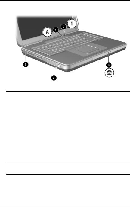
TouchPad
Component |
Description |
|
|
|
|
1 |
TouchPad* |
Moves the pointer and selects or |
|
|
activates items on the screen. |
|
|
|
2 |
Left and right TouchPad |
Function like the left and right buttons |
|
buttons |
of an external mouse. |
|
|
|
3 |
TouchPad scroll pad |
Functions like the wheel of an external |
|
|
mouse for scrolling up and down. |
|
|
|
4 |
TouchPad on/off button |
Turns TouchPad on or off. |
|
|
|
5 |
TouchPad light |
On: TouchPad is enabled. |
*For information about TouchPad settings, see Chapter 2, “TouchPad and Keyboard.”
Hardware Guide |
1–3 |

Hardware Components
Component |
Description |
|
|
|
|
1 |
TouchPad* |
Moves the pointer and selects or |
|
|
activates items on the screen. |
|
|
|
2 |
Left and right TouchPad |
Function like the left and right buttons |
|
buttons |
on an external mouse. |
|
|
|
3 |
TouchPad on/off button |
Turns TouchPad on or off. |
|
|
|
4 |
TouchPad light |
On: TouchPad is enabled. |
*For information about TouchPad settings, see Chapter 2, “TouchPad and Keyboard.”
1–4 |
Hardware Guide |

Hardware Components
Top Components
Power Lights
Component |
Description |
|
|
|
|
1 |
Power button light |
On: Notebook is turned on. |
|
|
Blinking: Notebook is in Standby. |
|
|
Off: Notebook is off or in Hibernation. |
|
|
|
2 |
Power/Standby light |
On: Notebook is turned on. |
|
|
Blinking: Notebook is in Standby. |
|
|
Off: Notebook is off or in Hibernation. |
|
|
|
3 |
Battery light |
On: Battery pack is charging. |
|
|
Blinking: Battery pack has reached a |
|
|
low-battery condition. |
Off: AC power is applied, with battery pack either fully charged or not installed, or no AC power is applied.
Hardware Guide |
1–5 |

Hardware Components
Component |
Description |
|
|
|
|
1 |
Power button light |
On: Notebook is turned on. |
|
|
Blinking: Notebook is in Standby. |
|
|
Off: Notebook is off or in Hibernation. |
|
|
|
2 |
Power/Standby light |
On: Notebook is turned on. |
|
|
Blinking: Notebook is in Standby. |
|
|
Off: Notebook is off or in Hibernation. |
|
|
|
3 |
Battery light |
On: Battery pack is charging. |
|
|
Blinking: Battery pack has reached a |
|
|
low-battery condition. |
Off: AC power is applied, with battery pack either fully charged or not installed, or no AC power is applied.
1–6 |
Hardware Guide |

Hardware Components
Keyboard and Drive Lights
Component |
Description |
|
|
|
|
1 |
Caps lock light |
On: Caps lock is on. |
|
|
|
2 |
Num lock light |
On: Num lock or the internal |
|
|
keypad is on.* |
|
|
|
3 |
IDE (Integrated Drive |
On: The internal hard drive or optical |
|
Electronics) light; also |
drive bay is being accessed. |
|
referred to as hard |
|
|
drive/optical drive activity |
|
|
light |
|
|
|
|
4 |
Optical disk drive light |
On: The optical drive bay is being |
|
|
accessed. |
|
|
|
5 |
5-in-1 Digital Media slot light |
On: Slot is accessing an optional |
|
(select models). |
digital media card. |
*For information about using num lock, the internal keypad, or an external keypad, see Chapter 2, “TouchPad and Keyboard.”
Hardware Guide |
1–7 |
Hardware Components
Component |
Description |
|
|
|
|
1 |
Caps lock light |
On: Caps lock is on. |
|
|
|
2 |
Num lock light |
On: Num lock or the internal |
|
|
keypad is on.* |
|
|
|
3 |
IDE (Integrated Drive |
On: The internal hard drive or the |
|
Electronics) light; also |
optical drive bay is being accessed. |
|
referred to as hard |
|
|
drive/optical drive activity |
|
|
light |
|
|
|
|
4 |
Optical disk drive light |
On: The optical drive bay is being |
|
|
accessed. |
|
|
|
5 |
5-in-1 Digital Media slot light |
On: Slot is accessing an optional |
|
(select models) |
digital media card. |
*For information about using num lock, the internal keypad, or an external keypad, see Chapter 2, “TouchPad and Keyboard.”
1–8 |
Hardware Guide |
Hardware Components
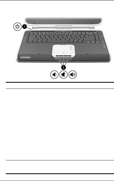
Power and Volume Controls
Component Description
1 Power button* When the notebook is:
■Off, press the button to turn on the notebook.
■On, briefly press the button to initiate Hibernation.
■In Standby, briefly press the button to resume from Standby.
■In Hibernation, briefly press the button to resume from Hibernation.
|
If the system has stopped responding |
|
and Windows shutdown procedures cannot |
|
be used, press and hold the button for at least |
|
4 seconds to turn off the notebook. |
|
|
2 Volume |
Decrease, mute, and increase the system volume: |
buttons (3) |
■ To decrease volume, use the left button. |
|
|
|
■ To mute or restore volume, use the middle button. |
|
■ To increase volume, use the right button. |
*This table describes default settings. For information about changing the function of the power button, refer to the “Power” chapter in the Software Guide on this CD.
Hardware Guide |
1–9 |
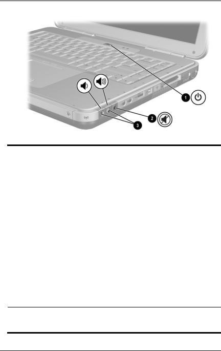
Hardware Components
Component |
Description |
|
|
|
|
1 |
Power button* |
When the notebook is: |
|
|
■ Off, press the button to turn on the notebook. |
|
|
■ On, briefly press the button to initiate Hibernation. |
|
|
■ In Standby, briefly press the button to resume |
|
|
from Standby. |
|
|
■ In Hibernation, briefly press the button to resume |
|
|
from Hibernation. |
|
|
If the system has stopped responding and |
|
|
Microsoft® Windows® shutdown |
|
|
procedures cannot be used, press and hold |
|
|
the button for at least 4 seconds to turn off |
|
|
the notebook. |
|
|
|
2 |
Mute button |
On: Audio is muted. |
|
|
|
3 |
Volume |
Decrease and increase the system volume: |
|
buttons (2) |
■ To decrease volume, use the left button. |
|
|
|
■ To increase volume, use the right button.
*This table describes default settings. For information about changing the function of the power button, refer to the “Power” chapter in the Software Guide on this CD.
1–10 |
Hardware Guide |

Hardware Components
Quick Launch Buttons and Keyboard Keys
Component |
Description |
|
|
1 Quick Launch buttons: |
From left to right: 3 programmable |
Picture, Media, and Internet |
buttons enable you to access the |
|
My Pictures folder, a multimedia |
|
application, and the Internet with |
|
one keystroke. |
|
The icon on each button represents the |
|
default destination. Buttons can be |
|
programmed to point to other locations. |
|
See the instructions on |
|
changing the destination of |
|
Quick Launch buttons in |
|
Chapter 2, “TouchPad and |
|
Keyboard.” |
|
|
|
(continued) |
Hardware Guide |
1–11 |

Hardware Components
2 |
Wireless On/Off button |
Enables wireless functionality, but does |
|
|
not create a wireless connection. |
|
|
To set up and complete a |
|
|
wireless connection, additional |
|
|
hardware and software might |
|
|
be required. |
|
|
|
3 |
Windows logo key |
Displays Windows Start menu. |
|
|
|
4 |
Windows Applications key |
Displays shortcut menu for any |
|
|
highlighted items. |
|
|
|
1–12 |
Hardware Guide |
Hardware Components
Wireless On/Off Button and
Application Keys
Component |
Description |
|
|
|
|
1 |
Wireless On/Off button |
Enables wireless functionality, but |
|
|
does not create a wireless connection. |
|
|
To set up and complete a |
|
|
wireless connection, |
|
|
additional hardware and |
|
|
software might be required. |
|
|
|
2 |
Windows logo key |
Displays Windows Start menu. |
|
|
|
3 |
Windows Applications key |
Displays shortcut menu for any |
|
|
highlighted items. |
|
|
|
Hardware Guide |
1–13 |
Hardware Components
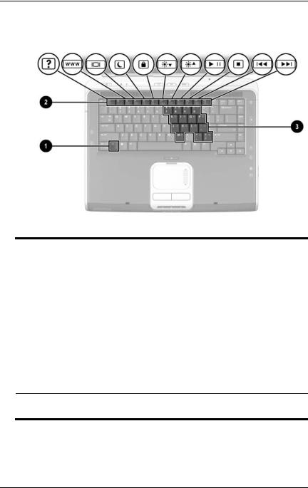
Function and Keypad Keys
Component |
Description |
|
|
|
|
1 |
Fn key |
Combines with the function keys to |
|
|
perform additional system and |
|
|
application tasks. For example, |
|
|
pressing Fn+F8 increases screen |
|
|
brightness. |
|
|
|
2 |
Function keys (11)* |
Perform system and application tasks. |
|
|
When combined with the Fn key, |
|
|
function keys F1 through F12 perform |
|
|
additional tasks as hotkeys. (The |
|
|
F2 function key is not used.) |
|
|
|
3 |
Keypad keys (15) |
Can be used like the keys on an |
|
|
external numeric keypad. |
*For more information, refer to the “Hotkey Quick Reference” section in Chapter 2, “TouchPad and Keyboard.”
1–14 |
Hardware Guide |

Hardware Components
Component |
Description |
|
|
|
|
1 |
Fn key |
Combines with the function keys to |
|
|
perform additional system and |
|
|
application tasks. For example, |
|
|
pressing Fn+F8 increases screen |
|
|
brightness. |
|
|
|
2 |
Function keys (11)* |
Perform system and application tasks. |
|
|
When combined with the Fn key, |
|
|
function keys F1 through F12 perform |
|
|
additional tasks as hotkeys. (The |
|
|
F2 function key is not used.) |
|
|
|
3 |
Keypad keys (15) |
Can be used like the keys on an |
|
|
external numeric keypad. |
*For more information, refer to the “Hotkey Quick Reference” section in Chapter 2, “TouchPad and Keyboard.”
Hardware Guide |
1–15 |
Hardware Components
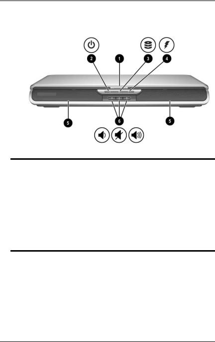
Front Components
Component |
Description |
|
|
|
|
1 |
Display release latch |
Opens the notebook. |
|
|
|
2 |
Power/Standby light |
On: Notebook is turned on. |
|
|
Blinking: Notebook is in Standby. |
|
|
Off: Notebook is off or in Hibernation. |
|
|
|
3 |
IDE (Integrated Drive |
On: The internal hard drive or optical |
|
Electronics) light; also |
drive bay is being accessed. |
|
referred to as hard |
|
|
drive/optical drive activity |
|
|
light |
|
(continued)
1–16 |
Hardware Guide |

|
|
|
Hardware Components |
|
|
|
|
4 |
Battery light |
On: Battery pack is charging. |
|
|
|
|
Blinking: Battery pack has reached a |
|
|
|
low-battery condition. |
|
|
|
Off: AC power is applied, with battery |
|
|
|
pack either fully charged or not |
|
|
|
installed, or no AC power is applied. |
|
|
|
|
5 |
Stereo speakers (2) |
Produce stereo sound. |
|
6Volume and mute buttons (3) Decrease, mute, and increase the
system volume:
■To decrease volume, use the left button.
■To mute or restore volume, use the middle button.
■To increase volume, use the right button.
Hardware Guide |
1–17 |

Hardware Components
Component |
Description |
|
|
|
|
1 |
Stereo speakers (2) |
Produce stereo sound. |
|
|
|
2 |
Power/Standby light |
On: Notebook is turned on. |
|
|
Blinking: Notebook is in Standby. |
|
|
Off: Notebook is off or in Hibernation. |
|
|
|
3 |
Display release latch |
Opens the notebook. |
4IDE (Integrated Drive Electronics) light; also referred to as hard drive/optical drive activity light
On: The internal hard drive or optical drive bay is being accessed.
1–18 |
Hardware Guide |

|
|
|
Hardware Components |
|
|
|
|
5 |
Battery light |
On: Battery pack is charging. |
|
|
|
|
Blinking: Battery pack has reached a |
|
|
|
low-battery condition. |
|
|
|
Off: AC power is applied, with battery |
|
|
|
pack either fully charged or not |
|
|
|
installed, or no AC power is applied. |
|
|
|
|
6 |
Wireless On/Off button |
Enables wireless functionality, but |
|
|
|
|
does not create a wireless connection. |
To set up and complete a wireless connection, additional hardware and software might be required.
Hardware Guide |
1–19 |

Hardware Components
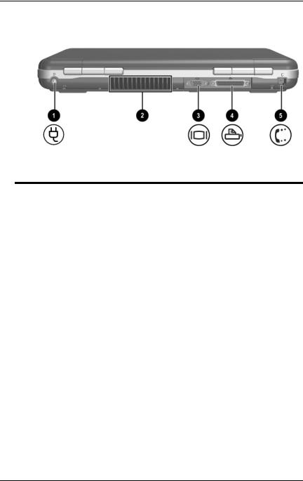
Rear Components
Component |
Description |
|
|
|
|
1 |
Power connector |
Connects an AC adapter. |
|
|
|
2 |
Exhaust vent |
Allows airflow to cool internal |
|
|
components. Additional vents are on |
|
|
the bottom of the notebook. |
|
|
Ä To prevent overheating, do |
|
|
not obstruct the vent. Do not |
|
|
allow a hard surface, such as |
|
|
an adjoining printer, or a soft |
|
|
surface, such as bedding or |
|
|
clothing, to block airflow. |
|
|
|
3 |
External monitor connector |
Connects an optional external monitor |
|
|
or overhead projector. |
|
|
|
4 |
Parallel connector |
Connects an optional parallel device, |
|
|
such as a printer. |
|
|
|
5 |
RJ-11 jack |
Connects the modem cable. |
|
|
|
1–20 |
Hardware Guide |
Hardware Components
Component |
Description |
|
|
|
|
1 |
Power connector |
Connects an AC adapter. |
|
|
|
2 |
Exhaust vent |
Allows airflow to cool internal |
|
|
components. Additional vents are |
|
|
on the bottom of the notebook. |
|
|
Ä To prevent overheating, do |
|
|
not obstruct the vent. Do not |
|
|
allow a hard surface, such as |
|
|
an adjoining printer, or a soft |
|
|
surface, such as bedding or |
|
|
clothing, to block airflow. |
|
|
|
3 |
External monitor connector |
Connects an optional external monitor |
|
|
or overhead projector. |
|
|
|
4 |
Parallel connector |
Connects an optional parallel device, |
|
|
such as a printer. |
|
|
|
5 |
RJ-11 jack (select models) |
Connects the modem cable. |
|
|
(select models) |
|
|
|
Hardware Guide |
1–21 |
Hardware Components
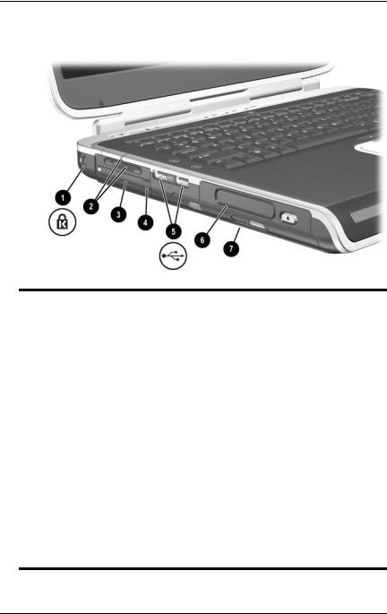
Left-Side Components
1
Component |
Description |
|
|
|
|
1 |
Security cable slot |
Attaches an optional security cable to |
|
|
the notebook. |
|
|
The purpose of security |
|
|
solutions is to act as a |
|
|
deterrent. These solutions do |
|
|
not prevent the product from |
|
|
being mishandled or stolen. |
|
|
|
2 |
5-in-1 Digital Media slot and |
Supports 5 optional digital media |
|
light (select models) |
formats: SD Memory Card, |
|
|
MultiMediaCard, SmartMedia, Memory |
|
|
Stick, and Memory Stick Pro. |
|
|
Light On: Slot is accessing digital |
|
|
media. |
|
|
|
3 |
PC Card slot |
Supports an optional Type I or Type II |
|
|
32-bit (CardBus) or 16-bit PC Card. |
|
|
|
4 |
PC Card eject button |
Ejects an optional PC Card from the |
|
|
PC Card slot. |
(continued)
1–22 |
Hardware Guide |
Loading...