


 Loading...
Maintenance and Service
Guide
HP Pavilion zd8000 Notebook PC
Document Part Number: 372712-002
February 2008
This guide is a troubleshooting reference used for maintaining and servicing the notebook. It provides comprehensive information on identifying notebook features, components, and spare parts; troubleshooting notebook problems; and performing notebook disassembly procedures.
© Copyright 2005–2008 Hewlett-Packard Development Company, L.P.
Microsoft and Windows are U.S. registered trademarks of Microsoft Corporation. Intel and Pentium are trademarks or registered trademarks of Intel Corporation or its subsidiaries in the United States and other countries. Bluetooth is a trademark owned by its proprietor and used by Hewlett-Packard Company under license. SD logo is a trademark of its proprietor.
The information contained herein is subject to change without notice. The only warranties for HP products and services are set forth in the express warranty statements accompanying such products and services. Nothing herein should be construed as constituting an additional warranty. HP shall not be liable for technical or editorial errors or omissions contained herein.
Maintenance and Service Guide
HP Pavilion zd8000 Notebook PC
Second Edition: February 2008
First Edition: January 2005
Document Part Number: 372712-002

Contents
1 Product Description
1.1 Features . . . . . . . . . . . . . . . . . . . . . . . . . . . . . . . . . . 1–2
1.2 Resetting the Notebook . . . . . . . . . . . . . . . . . . . . . . 1–4
1.3 Power Management . . . . . . . . . . . . . . . . . . . . . . . . . 1–4
1.4 External Components. . . . . . . . . . . . . . . . . . . . . . . . 1–5
1.5 Design Overview . . . . . . . . . . . . . . . . . . . . . . . . . . 1–18
2 Troubleshooting
2.1 Computer Setup . . . . . . . . . . . . . . . . . . . . . . . . . . . . 2–1
2.2 Troubleshooting Flowcharts. . . . . . . . . . . . . . . . . . . 2–5
3 Illustrated Parts Catalog
3.1 Serial Number Location . . . . . . . . . . . . . . . . . . . . . . 3–1
3.2 Notebook Major Components . . . . . . . . . . . . . . . . . 3–2
3.3 Miscellaneous Plastics Kit . . . . . . . . . . . . . . . . . . . . 3–8
3.4 Mass Storage Devices . . . . . . . . . . . . . . . . . . . . . . . 3–9
3.5 Media Center Edition Accessories. . . . . . . . . . . . . 3–10
3.6 Miscellaneous (Not Illustrated) . . . . . . . . . . . . . . . 3–11
3.7 Sequential Part Number Listing. . . . . . . . . . . . . . . 3–14
4 Removal and Replacement Preliminaries
4.1 Tools Required. . . . . . . . . . . . . . . . . . . . . . . . . . . . . 4–1 4.2 Service Considerations. . . . . . . . . . . . . . . . . . . . . . . 4–2 4.3 Preventing Damage to Removable Drives . . . . . . . . 4–3 4.4 Preventing Electrostatic Damage . . . . . . . . . . . . . . . 4–4 4.5 Packaging and Transporting Precautions. . . . . . . . . 4–5 4.6 Workstation Precautions . . . . . . . . . . . . . . . . . . . . . 4–6 4.7 Grounding Equipment and Methods . . . . . . . . . . . . 4–7
Maintenance and Service Guide |
1 |

Contents
5 Removal and Replacement Procedures
5.1 Serial Number . . . . . . . . . . . . . . . . . . . . . . . . . . . . . 5–2 5.2 Disassembly Sequence Chart . . . . . . . . . . . . . . . . . . 5–3 5.3 Preparing the Notebook for Disassembly . . . . . . . . 5–5 5.4 Notebook Feet . . . . . . . . . . . . . . . . . . . . . . . . . . . . 5–11 5.5 Optical Drive . . . . . . . . . . . . . . . . . . . . . . . . . . . . . 5–12 5.6 Memory Module. . . . . . . . . . . . . . . . . . . . . . . . . . . 5–14 5.7 Mini PCI Communications Card . . . . . . . . . . . . . . 5–16 5.8 Switch Cover . . . . . . . . . . . . . . . . . . . . . . . . . . . . . 5–18 5.9 LED Board . . . . . . . . . . . . . . . . . . . . . . . . . . . . . . . 5–20 5.10 Keyboard . . . . . . . . . . . . . . . . . . . . . . . . . . . . . . . 5–22 5.11 Display Assembly . . . . . . . . . . . . . . . . . . . . . . . . 5–26 5.12 Top Cover. . . . . . . . . . . . . . . . . . . . . . . . . . . . . . . 5–30 5.13 Infrared Board . . . . . . . . . . . . . . . . . . . . . . . . . . . 5–34 5.14 Audio/USB Board . . . . . . . . . . . . . . . . . . . . . . . . 5–36 5.15 Bluetooth Board . . . . . . . . . . . . . . . . . . . . . . . . . . 5–38 5.16 System Board . . . . . . . . . . . . . . . . . . . . . . . . . . . . 5–40 5.17 Speakers . . . . . . . . . . . . . . . . . . . . . . . . . . . . . . . . 5–45 5.18 USB Digital Drive Board. . . . . . . . . . . . . . . . . . . 5–48 5.19 Base Enclosure Fans . . . . . . . . . . . . . . . . . . . . . . 5–50 5.20 Modem Board. . . . . . . . . . . . . . . . . . . . . . . . . . . . 5–52 5.21 Heat Sink Module . . . . . . . . . . . . . . . . . . . . . . . . 5–54 5.22 Processor . . . . . . . . . . . . . . . . . . . . . . . . . . . . . . . 5–56
6 Specifications
AConnector Pin Assignments
BPower Cord Set Requirements
CScrew Listing
Index
2 |
Maintenance and Service Guide |
1
Product Description
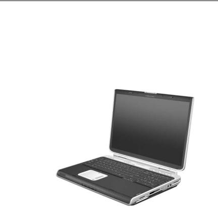
The HP Pavilion zd8000 Notebook PC offers advanced modularity, Intel® Mobile Pentium® 4 processors, and extensive multimedia support.
HP Pavilion zd8000 Notebook PC
Maintenance and Service Guide |
1–1 |

Product Description
1.1Features
The following processors are available, varying by notebook model:
Intel Pentium 4 560 (3.6-GHz) with 800-MHz front side bus (FSB) with HT Technology
Intel Pentium 4 550 (3.4-GHz) with 800-MHz FSB with HT Technology
Intel Pentium 4 540 (3.2-GHz) with 800-MHz FSB with HT Technology
Intel Pentium 4 530 (3.0-GHz) with 800-MHz FSB with HT Technology
Intel Pentium 4 520 (2.8-GHz) with 800-MHz FSB with HT Technology
The following displays are available, varying by notebook model:
17.0-inch WSXGA+WVA (1680 × 1050) with Brightview TFT display with over 16.7 million colors
17.0-inch WXGA+WVA (1440 × 900) with Brightview TFT display with over 16.7 million colors
17.0-inch WXGA+WVA (1440 × 900) TFT display with over 16.7 million colors
100-, 80-, 60-, or 40-GB high-capacity hard drive, varying by notebook model
256-MB DDR2 synchronous DRAM (SDRAM) at 400 and 533 MHz, expandable to 2.0 GB
Microsoft® Windows® XP Home Edition or Windows XP Professional, varying by notebook model
Full-size Windows keyboard with full-size numeric keypad
TouchPad pointing device, including a dedicated vertical scroll region and a button that enables/disables TouchPad operation.
Integrated 10 Base-T/100 Base-TX Ethernet local area network (LAN) network interface card (NIC) with RJ-45 jack
1–2 |
Maintenance and Service Guide |

Product Description
Integrated high-speed 56K modem with RJ-11 jack
Integrated wireless support for Mini PCI IEEE 802.11b and 802.11b/g WLAN device
Support for one Type II PC Card slot, with support for both 32-bit (CardBus) and 16-bit PC Cards
External 180and 135-watt AC adapter with 3-wire power cord, varying by notebook model
12-cell Li-Ion battery pack
Stereo speakers with volume up, volume mute, and volume down buttons
Support for the following optical drives:
8X Max DVD±RW/R and CD-RW Combo Drive
24X Max DVD/CD-RW Combo Drive
Connectors:
External monitor
Universal Serial Bus (USB) v. 2.0 (four ports)
RJ-11 (modem)
RJ-45 (network)
Audio-out (headphone)
Audio-in (microphone)
Power
IEEE 1394 (select models only)
S-Video-out (select models only)
Infrared
Expansion port 2
Digital Media Slot
Digital drive bay
ExpressCard
Maintenance and Service Guide |
1–3 |

Product Description
1.2 Resetting the Notebook
If the notebook you are servicing has an unknown password, follow these steps to clear the password. These steps also clear CMOS:
1.Prepare the notebook for disassembly (refer to Section 5.3, “Preparing the Notebook for Disassembly,” for more information).
2.Remove the real time clock (RTC) battery (refer to Section 5.16, “System Board,” for more information on removing and replacing the RTC battery).
3.Wait approximately 5 minutes.
4.Replace the RTC battery and reassemble the notebook.
5.Connect AC power to the notebook. Do not reinsert any battery packs at this time.
6.Turn on the notebook.
All passwords and all CMOS settings have been cleared.
1.3 Power Management
The notebook comes with power management features that extend battery operating time and conserve power. The notebook supports the following power management features:
■Standby
■Hibernation
■Setting customization by the user
■Hotkeys for setting the level of performance
■Battery calibration
■Lid switch standby/resume
■Power/standby button
■Advanced Configuration and Power Management (ACPM) compliance
1–4 |
Maintenance and Service Guide |
Product Description
1.4 External Components
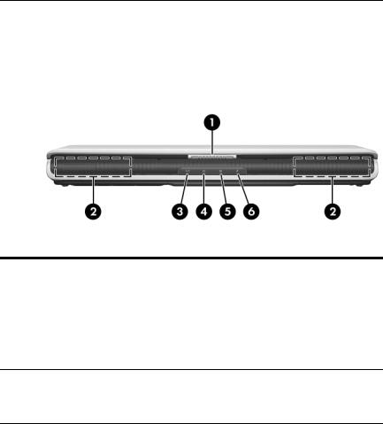
The external components on the front of the notebook are shown below and described in Table 1-1.
Front Components
|
|
Table 1-1 |
|
Front Components |
|
|
|
|
Item |
Component |
Function |
|
|
|
1 |
Display release latch |
Opens the notebook. |
|
|
|
2 |
Stereo speakers (2) |
Produce stereo sound. |
3Power/standby light ■ On: Notebook is turned on.
■Blinking: Notebook is in standby.
■Off: Notebook is off.
4 |
Battery light |
■ |
On: Battery pack is charging. |
|
|
■ Blinking: Battery pack has reached a |
|
|
|
|
low-battery condition. |
|
|
|
|
5 |
AC power light |
On: Notebook is receiving AC power. |
|
|
|
|
|
6 |
Hard drive activity light |
On: A notebook drive is being accessed. |
|
|
|
|
|
Maintenance and Service Guide |
1–5 |

Product Description
The external components on the right side of the notebook are shown below and described in Table 1-2.
Right-Side Components
Table 1-2
Right-Side Components
Item |
Component |
Function |
|
|
|
1 |
Digital Media Slot |
Supports the following optional digital |
|
|
media: Secure Digital (SD) Memory Card, |
|
|
Secure Digital Input/Output (SD I/O), |
|
|
Memory Stick, Memory Stick Pro, |
|
|
MultiMediaCard, xD-Picture Card, and |
|
|
SmartMedia card. |
|
|
|
2 |
ExpressCard slot |
Supports an optional ExpressCard. |
|
|
|
3 |
1394 port |
Connects an optional 1394a device such |
|
|
as a scanner, digital camera, or digital |
|
|
camcorder. |
|
|
|
1–6 |
Maintenance and Service Guide |
Product Description
Table 1-2
Right-Side Components (Continued)
Item |
Component |
Function |
|
|
|
4 |
Expansion port 2 |
Connects to an optional notebook |
|
|
expansion product. |
|
|
|
5 |
PC Card eject button |
Ejects an optional PC Card from the |
|
|
PC Card slot. |
|
|
|
6 |
PC Card slot |
Supports an optional Type I or Type II 32-bit |
|
|
(CardBus) or 16-bit PC Card. |
|
|
Also serves as a storage location for the |
|
|
optional mobile remote control. |
|
|
|
7 |
Digital drive bay |
Supports an optional USB digital drive. |
|
|
|
8 |
Digital drive eject |
Ejects an optional USB digital drive from the |
|
button |
digital drive bay. |
|
|
|
9 |
USB ports (2) |
Connect an optional 1.1- or 2.0-compliant |
|
|
USB device. |
|
|
|
10 |
RJ-11 (modem) jack |
Connects the modem cable. |
|
|
|
11 |
RJ-45 (network) jack |
Connects an optional network cable. |
|
|
|
12 |
Exhaust vent |
Provides airflow to cool internal |
|
|
components. |
Ä To prevent overheating, do not obstruct vents. Do not allow a hard surface, such as a printer, or a soft surface, such as pillows, thick rugs or clothing, to block airflow.
Maintenance and Service Guide |
1–7 |
Product Description
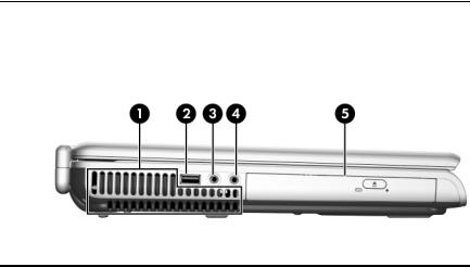
The external components on the left side of the notebook are shown below and described in Table 1-3.
Left-Side Components
|
|
Table 1-3 |
|
Left-Side Components |
|
|
|
|
Item |
Component |
Function |
|
|
|
1 |
Exhaust vent |
Provides airflow to cool internal |
|
|
components. |
|
|
ÄTo prevent overheating, do not |
|
|
obstruct vents. Do not allow a hard |
|
|
surface, such as a printer, or a soft |
|
|
surface, such as pillows, thick rugs |
|
|
or clothing, to block airflow. |
|
|
|
2 |
USB port |
Connects an optional 1.1- or 2.0-compliant |
|
|
USB device. |
|
|
|
3 |
Audio-in |
Connects an optional monaural |
|
(microphone) jack |
microphone. |
|
|
|
4 |
Audio-out |
Connect optional headphones or powered |
|
(headphone) jack (2) |
stereo speakers. Also connects the audio |
|
|
function of an audio/video device such as |
|
|
a television or VCR. |
|
|
|
5 |
Optical drive |
Supports an optical disc. The type of |
|
|
optical drive, such as a combination |
|
|
CD-ROM/DVD-ROM, varies by model. |
|
|
|
1–8 |
Maintenance and Service Guide |

Product Description
The external components on the rear panel of the notebook are shown below and described in Table 1-4.
Rear Panel Components
Table 1-4
Rear Panel Components
Item |
Component |
Function |
|
|
|
1 |
Security cable slot |
Attaches an optional security cable to the |
|
|
notebook. |
|
|
|
2 |
Power connector |
Connects an AC adapter. |
|
|
|
3 |
USB port |
Connects an optional 1.1- or 2.0-compliant |
|
|
USB device. |
|
|
|
4 |
S-Video-out jack |
Connects an optional S-Video device, |
|
|
such as a television, VCR, camcorder, |
|
|
projector, or video capture card. |
|
|
|
5 |
External monitor port |
Connects an optional VGA external |
|
|
monitor or projector. |
|
|
|
6 |
Exhaust vent |
Provides airflow to cool internal |
|
|
components. |
ÄTo prevent overheating, do not obstruct vents. Do not allow a hard surface, such as a printer, or a soft surface, such as pillows, thick rugs or clothing, to block airflow.
Maintenance and Service Guide |
1–9 |
Product Description
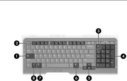
The standard keyboard components of the notebook are shown below and described in Table 1-5.
Standard Keyboard Components
1–10 |
Maintenance and Service Guide |

Product Description
Table 1-5
Standard Keyboard Components
Item |
Component |
Function |
|
|
|
1 |
caps lock key |
Enables caps lock and turns on the |
|
|
caps lock light. |
|
|
|
2 |
f1 to f12 keys (12) |
Perform system and application tasks. |
|
|
When combined with the fn key, several |
|
|
keys and buttons perform additional tasks |
|
|
as hotkeys. |
|
|
|
3 |
num lock key |
Enables numeric lock, turns on the |
|
|
embedded numeric keypad, and turns |
|
|
on the num lock light. |
|
|
|
4 |
Keypad keys (15) |
In Windows, can be used like the keys |
|
|
on an external numeric keypad. |
|
|
|
5 |
Arrow keys |
Moves the cursor around the screen. |
|
|
|
6 |
Windows |
In Windows, displays a shortcut menu |
|
applications key |
for items beneath the pointer. |
|
|
|
7 |
Windows logo key |
In Windows, displays the Windows |
|
|
Start menu. |
|
|
|
8 |
fn key |
Combines with other keys to perform |
|
|
system tasks. For example, pressing |
|
|
fn+f7 decreases screen brightness. |
|
|
|
Maintenance and Service Guide |
1–11 |
Product Description
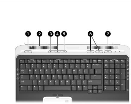
The upper components of the keyboard are shown below and on the following page and described in Tables 1-6 and 1-7.
Upper Keyboard Components
1–12 |
Maintenance and Service Guide |

Product Description
Table 1-6
Upper Keyboard Components
Item |
Component |
Function |
|
|
|
1 |
Power/standby button |
When the notebook is: |
|
|
■ Off, press to turn on the notebook. |
|
|
■ On, briefly press to initiate standby. |
|
|
■ In standby, briefly press to resume from |
|
|
standby. |
|
|
■ In hibernation, briefly press to restore |
|
|
from hibernation. |
|
|
If the system has stopped |
|
|
responding and Microsoft Windows |
|
|
shutdown procedures cannot be |
|
|
used, press and hold the |
|
|
power/standby button for at least |
|
|
4 seconds to turn off the notebook. |
|
|
|
2 |
Exhaust vents |
Provide airflow to cool internal |
|
|
components. |
|
|
ÄTo prevent overheating, do not |
|
|
obstruct vents. Do not allow a hard |
|
|
surface, such as a printer, or a soft |
|
|
surface, such as pillows, thick rugs |
|
|
or clothing, to block airflow. |
|
|
|
3 |
Volume down button |
Decreases system volume. |
|
|
|
4 |
Volume mute button |
Mutes or restores system volume. |
|
|
|
5 |
Volume up button |
Increases system volume. |
|
|
|
6 |
Quick Launch buttons |
Launch default multimedia, digital |
|
(2) |
imaging, or music applications (varies by |
|
|
model). |
To reassign another application to a Quick Launch button, refer to “Using Custom Assignments and Schemes” in Chapter 2 of the Hardware and Software Guide included with the notebook.
Maintenance and Service Guide |
1–13 |
Product Description
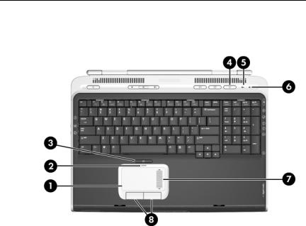
The top components of the notebook are shown below and described in Table 1-7.
Notebook Top Components
1–14 |
Maintenance and Service Guide |

Product Description
Table 1-7
Notebook Top Components
Item |
Component |
Function |
|
|
|
1 |
TouchPad |
Moves the pointer and selects or |
|
|
activates items on the screen. |
|
|
|
2 |
TouchPad light |
On: TouchPad is enabled. |
|
|
|
3 |
TouchPad button |
Enables/disables the TouchPad. |
|
|
|
4 |
Wireless button |
Turns the wireless network device on and |
|
|
off (select models only). |
|
Wireless light |
On: An integrated wireless device has |
|
|
been enabled. |
|
|
|
5 |
Caps lock light |
On: caps lock is on. |
|
|
|
6 |
Num lock light |
On: num lock or the numeric keypad is on. |
|
|
|
7 |
TouchPad scroll zone |
Scrolls up or down. |
|
|
|
8 |
Left and right TouchPad |
Function like the left and right buttons on |
|
buttons |
an external mouse. |
|
|
|
Maintenance and Service Guide |
1–15 |
Product Description
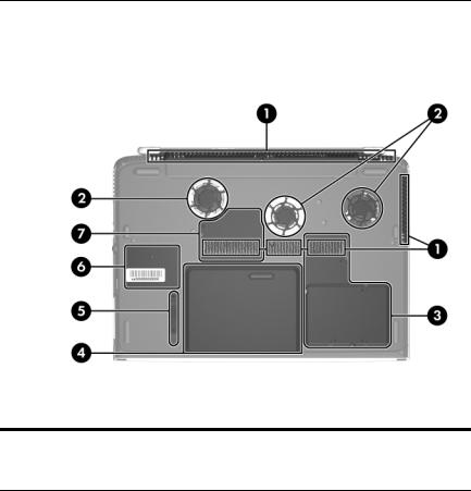
The external components on the bottom of the notebook are shown below and described in Table 1-8.
Bottom Components
Table 1-8
Bottom Components
Item |
Component |
Function |
|
|
|
1 |
Exhaust vents (4) |
Provide airflow to cool internal |
|
|
components. |
|
|
Ä To prevent overheating, do not |
|
|
obstruct vents. Do not allow a |
|
|
hard surface, such as a printer, or |
|
|
a soft surface, such as pillows, |
|
|
thick rugs or clothing, to block |
|
|
airflow. |
|
|
|
1–16 |
Maintenance and Service Guide |
Product Description
Table 1-8
Bottom Components (Continued)
Item |
Component |
Function |
|
|
|
2 |
Fans (2) |
Provide airflow to cool internal |
|
|
components. |
|
|
Ä To prevent overheating, do not |
|
|
obstruct fans. Do not allow a hard |
|
|
surface, such as a printer, or a |
|
|
soft surface, such as pillows, |
|
|
thick rugs or clothing, to block |
|
|
airflow. |
|
|
|
3 |
Hard drive bay |
Holds the internal hard drive. |
|
Mini PCI compartment |
Holds an optional wireless LAN device. |
|
|
Ä To prevent an unresponsive |
|
|
system and the display of a |
|
|
warning message, install only a |
|
|
Mini PCI device authorized for |
|
|
use in your notebook by the |
|
|
governmental agency that |
|
|
regulates wireless devices in your |
|
|
country. If you install a device |
|
|
and then receive a warning |
|
|
message, remove the device to |
|
|
restore notebook functionality. |
|
|
Then contact Customer Care. |
|
|
|
4 |
Battery bay |
Holds a battery pack. |
|
|
|
5 |
Battery pack release latch |
Releases a battery pack from the |
|
|
battery bay. |
|
|
|
6 |
Label areas (2) |
Contains the notebook serial number |
|
|
and other applicable regulatory labels. |
|
|
|
7 |
Memory module |
Contains two memory slots that support |
|
compartment |
replaceable memory modules. The |
|
|
number of preinstalled memory |
|
|
modules varies by notebook model. |
|
|
|
Maintenance and Service Guide |
1–17 |

Product Description
1.5 Design Overview
This section presents a design overview of key parts and features of the notebook. Refer to Chapter 3, “Illustrated Parts Catalog,” to identify replacement parts, and Chapter 5, “Removal and Replacement Procedures,” for disassembly steps.
The system board provides the following device connections:
■Memory module
■Mini PCI communications devices
■Hard drive
■Display
■Keyboard and TouchPad
■Audio
■Intel Pentium 4 processors
■PC Card
ÄCAUTION: To properly ventilate the notebook, allow at least a 7.6--cm (3-inch) clearance on the left and right sides of the notebook.
The notebook uses an electric fan for ventilation. The fan is controlled by a temperature sensor and is designed to be turned on automatically when high temperature conditions exist. These conditions are affected by high external temperatures, system power consumption, power management/battery conservation configurations, battery fast charging, and software applications. Exhaust air is displaced through the ventilation grill located on the left side of the notebook.
1–18 |
Maintenance and Service Guide |

2
Troubleshooting
ÅWARNING: Only authorized technicians trained by HP should repair this equipment. All troubleshooting and repair procedures are detailed to allow only subassembly-/module-level repair. Because of the complexity of the individual boards and subassemblies, do not attempt to make repairs at the component level or modifications to any printed wiring board. Improper repairs can create a safety hazard. Any indication of component replacement or printed wiring board modification may void any warranty or exchange allowances.
2.1Computer Setup
Computer Setup is a system information and customization utility that can be used even when your operating system is not working or will not load. This utility includes settings that are not available in Windows.
Using Computer Setup
Information and settings in Computer Setup are accessed from the Main, Security, Advanced, or Tools menus:
1.Turn on or restart the notebook. Press f10 while the F10 = ROM-Based Setup message is displayed in the lower-left corner of the screen.
To change the language, use the cursor control keys to navigate to the Advanced menu.
To view navigation information, press f1.
To return to the Computer Setup menu, press esc.
Maintenance and Service Guide |
2–1 |

Troubleshooting
2.Select the Main, Security, Advanced, or Tools menu.
3.To close Computer Setup and restart the notebook:
Select Exit > Exit Saving Changes, and then press enter.
– or –
Select Exit > Exit Discarding Changes, and then press enter.
– or –
Select Exit > Load Setup Defaults, and then press enter.
4.When you are prompted to confirm your action, press f10.
Selecting from the Main Menu
|
Table 2-1 |
|
Main Menu |
|
|
Select |
To Do This |
|
|
System Information |
■ Change the system time and system date. |
|
■ View identification information about the |
|
notebook. |
|
■ View specification information about the |
|
processor, memory and cache size, and |
|
system ROM. |
|
|
2–2 |
Maintenance and Service Guide |

Troubleshooting
Selecting from the Security Menu
|
Table 2-2 |
|
|
Security Menu |
|
|
|
|
Select |
To Do This |
|
|
|
|
Administrator Password |
Enter, change, or delete an Administrator |
|
|
password. |
|
|
|
|
Power-on Password |
Enter, change, or delete a power-on password. |
|
|
|
|
DriveLock Passwords |
Enable/disable DriveLock; change a DriveLock |
|
|
user or master password. |
|
|
DriveLock Settings are accessible only |
|
|
when you enter Computer Setup by turning |
|
|
on (not restarting) the notebook. |
|
|
|
|
Password Options |
Enable/disable: |
|
(Password options can |
■ QuickLock |
|
be selected only when |
■ QuickLock on standby |
|
a power-on password |
||
■ QuickBlank |
||
has been set.) |
||
|
||
|
To enable QuickLock on standby or |
|
|
QuickBlank, you must first enable |
|
|
QuickLock. |
|
|
|
|
Device Security |
Enable/disable: |
|
|
■ Diskette drive startup* |
|
|
■ CD-ROM or diskette startup |
|
|
Settings for a DVD-ROM can be entered |
|
|
in the CD-ROM field. |
*Not applicable to SuperDisk LS-120 drives.
Maintenance and Service Guide |
2–3 |

Troubleshooting
Selecting from the Advanced Menu
|
Table 2-3 |
|
Advanced Menu |
|
|
Select |
To Do This |
|
|
Language |
Change the Computer Setup language. |
|
|
Boot Order |
Enable/disable MultiBoot, which sets a startup |
|
sequence that can include most bootable devices |
|
and media in the system. |
|
|
Accessibility Options |
Allows electronic and information technology to |
|
be accessible to people with varying ranges of |
|
abilities. |
|
|
Video Memory |
Displays the amount of video memory available |
|
on the notebook. |
|
|
Selecting from the Tools Menu
|
Table 2-4 |
|
Tools Menu |
|
|
Select |
To Do This |
|
|
Hard Drive Self Test |
Run a quick comprehensive self test on hard |
|
drives in the system that support the test features. |
|
|
2–4 |
Maintenance and Service Guide |

Troubleshooting
2.2 Troubleshooting Flowcharts
|
Table 2-5 |
|
Troubleshooting Flowcharts Overview |
|
|
Flowchart |
Description |
|
|
2.1 |
“Flowchart 2.1—Initial Troubleshooting” |
|
|
2.2 |
“Flowchart 2.2—No Power, Part 1” |
|
|
2.3 |
“Flowchart 2.3—No Power, Part 2” |
|
|
2.4 |
“Flowchart 2.4—No Power, Part 3” |
|
|
2.5 |
“Flowchart 2.5—No Power, Part 4” |
|
|
2.6 |
“Flowchart 2.6—No Video, Part 1” |
|
|
2.7 |
“Flowchart 2.7—No Video, Part 2” |
|
|
2.8 |
“Flowchart 2.8—Nonfunctioning Expansion Base (if applicable)” |
|
|
2.9 |
“Flowchart 2.9—No Operating System (OS) Loading” |
|
|
2.10 |
“Flowchart 2.10—No OS Loading, Hard Drive, Part 1” |
|
|
2.11 |
“Flowchart 2.11—No OS Loading, Hard Drive, Part 2” |
|
|
2.12 |
“Flowchart 2.12—No OS Loading, Hard Drive, Part 3” |
|
|
2.13 |
“Flowchart 2.13—No OS Loading, Diskette Drive” |
|
|
Maintenance and Service Guide |
2–5 |

Troubleshooting
|
Table 2-5 |
Troubleshooting Flowcharts Overview (Continued) |
|
|
|
Flowchart |
Description |
|
|
2.14 |
“Flowchart 2.14—No OS Loading, Optical Drive” |
|
|
2.15 |
“Flowchart 2.15—No Audio, Part 1” |
|
|
2.16 |
“Flowchart 2.16—No Audio, Part 2” |
|
|
2.17 |
“Flowchart 2.17—Nonfunctioning Device” |
|
|
2.18 |
“Flowchart 2.18—Nonfunctioning Keyboard” |
|
|
2.19 |
“Flowchart 2.19—Nonfunctioning Pointing Device” |
|
|
2.20 |
“Flowchart 2.20—No Network/Modem Connection” |
|
|
2–6 |
Maintenance and Service Guide |

Troubleshooting
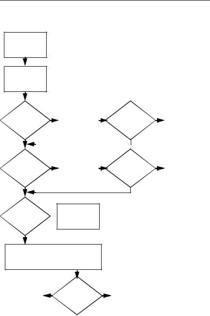
Flowchart 2.1—Initial Troubleshooting
Begin  troubleshooting.
|
N |
|
Is there |
|
Go to |
|
“Flowchart |
|
power? |
|
2.2—No Power, |
|
|
Part 1.” |
Y
N |
|
|
|
|
Beeps, |
Check |
|
|
|
LED board, |
|
|
|
|
LEDs, or error |
|
N |
|
|
speaker |
|
|
||
messages? |
|
|
||
connections. |
|
|
Go to |
|
Y |
|
|
||
|
All drives |
|
||
|
|
“Flowchart |
||
|
|
working? |
|
2.17—Nonfunction |
N |
|
Y |
|
ing Device.” |
|
|
|
||
|
Go to |
|
|
|
Is there video? |
|
|
|
|
“Flowchart |
|
N |
Go to |
|
(no boot) |
2.6—No Video, |
|
||
|
“Flowchart |
|||
|
Part 1.” |
Keyboard/ |
|
|
Y |
|
2.18—Nonfunction |
||
|
|
|||
|
pointing |
|
ing Keyboard” or |
|
|
|
device |
|
“Flowchart |
N |
|
working? |
|
2.19—Nonfunction |
|
|
ing Pointing |
||
|
Go to |
Y |
|
|
Is the OS |
|
|
Device.” |
|
“Flowchart |
|
|
||
|
|
|
||
loading? |
2.9—No Operating |
|
N |
|
|
System (OS) |
Connecting |
|
Go to |
Y |
Loading.” |
|
||
|
“Flowchart |
|||
|
|
to network |
|
2.20—No |
|
|
or modem? |
|
|
N |
|
|
Network/Modem |
|
|
|
|
||
|
Y |
|
Connection.” |
|
|
Go to |
|
||
Is there |
|
|
|
|
“Flowchart |
|
|
|
|
sound? |
2.15—No Audio, |
|
|
|
Y |
Part 1.” |
End |
|
|
|
|
|
|
Maintenance and Service Guide |
2–7 |
Troubleshooting
Flowchart 2.2—No Power, Part 1
No power (power LED is off).
Remove from expansion base (if applicable).
|
|
N |
|
|
N |
||
Power up |
|
Reset |
Power up |
|
Go to |
||
|
|
“Flowchart |
|||||
on battery |
|
on battery |
|
||||
|
power.* |
|
2.3—No Power, |
||||
power? |
|
power? |
|
||||
|
|
|
Part 2.” |
||||
Y |
|
|
Y |
|
|||
|
|
|
|
||||
|
|
|
|
|
|
||
|
|
N |
|
|
N |
||
Power up |
|
Reset |
Power up |
|
Go to |
||
|
|
“Flowchart |
|||||
on AC |
|
on |
AC |
|
|||
|
power.* |
|
2.4—No Power, |
||||
power? |
|
power? |
|
||||
|
|
|
Part 3.” |
||||
Y |
|
|
Y |
|
|||
|
|
|
|
||||
Y
Power up in
docking 
 Done device?
N
1.Reseat the power cables in the expansion base and at the AC outlet.
2.Ensure the AC power source is active.
3.Ensure that the power strip is working.
*NOTES
1.On select models, there is a separate reset button.
2.On select models, the notebook can be reset using the standby switch and either the lid switch or the main power switch.
|
Y |
N |
|
|
Go to |
||
|
Power up |
|
|
Done |
|
“Flowchart |
|
in expansion |
|
2.8—Nonfunctioning |
|
|
base? |
|
Expansion Base (if |
|
|
|
applicable).” |
|
|
||
|
|
|
|
2–8 |
Maintenance and Service Guide |
Loading...