

Page 1

Service Manual
iTNC 530
July 2010
Page 2

Page 3

1 How to Use this Service Manual........................................................................................ 11
1.1 Target Group.................................................................................................................. 11
1.2 About this Manual ......................................................................................................... 11
1.3 Other Service Manuals.................................................................................................. 12
1.4 Other Documentation.................................................................................................... 12
1.5 Support.......................................................................................................................... 12
1.6 Service Training ............................................................................................................. 12
1.7 Meaning of the Symbols Used in this Manual............................................................... 13
1.8 Safety ............................................................................................................................ 13
2 Safety Precautions............................................................................................................... 15
2.1 Overview ....................................................................................................................... 15
3 Code Numbers ..................................................................................................................... 17
3.1 Introduction ................................................................................................................... 17
3.2 Overview ....................................................................................................................... 17
3.3 Input of Code Numbers ................................................................................................ 18
4 Error Messages .................................................................................................................... 21
4.1 Introduction ................................................................................................................... 21
4.2 HELP Key....................................................................................................................... 25
4.3 ERR Key ........................................................................................................................ 26
4.4 CE Key .......................................................................................................................... 28
4.5 List of NC Error Messages ............................................................................................ 29
5 Errors Patterns ..................................................................................................................... 55
5.1 Introduction ................................................................................................................... 55
5.2 Overview of Possible Error Patterns ............................................................................. 55
6 Procedures and Tips for Error Diagnosis........................................................................... 59
6.1 Introduction ................................................................................................................... 59
6.2 Power Off and On ......................................................................................................... 59
6.3 Sequence for Finding Serious Electrical Errors.............................................................. 60
6.4 Sequence for Finding Errors in the Control Loop .......................................................... 62
6.5 Error Localization by Process of Interchange ................................................................ 65
6.6 Error Localization by Process of Exclusion .................................................................... 66
6.7 Finding Position Differences of Direct and Indirect Encoder......................................... 68
6.8 Error Localization by Switching from Direct to Indirect Position Measurement............ 70
6.9 Notes and Tips............................................................................................................... 72
7 Creating and Downloading of Service Files ...................................................................... 77
7.1 Introduction ................................................................................................................... 77
7.2 Automatic Generation of Service Files .......................................................................... 78
7.3 Automatic Generation of Service Files .......................................................................... 78
7.4 Downloading of Service Files ........................................................................................ 79
8 Log......................................................................................................................................... 81
8.1 Introduction ................................................................................................................... 81
8.2 Calling the Log............................................................................................................... 82
verview of Log En
8.3 O
8.4 Log Entries at Program Cancelation .............................................................................. 87
9 Integrated Diagnostic Functions and DriveDiag ............................................................... 89
9.1 Introduction ................................................................................................................... 89
9.2 Activation and Operation ............................................................................................... 90
9.3 For Error Diagnosis........................................................................................................ 98
10 Integrated Oscilloscope..................................................................................................... 99
10.1 Introduction ................................................................................................................. 99
10.2 Activation and Settings.............................................................................................. 100
10.3 Recording and Adjusting the Signals......................................................................... 105
10.4 Saving and Loading Recordings................................................................................. 110
tries................................................................................................ 83
July 2010 HEIDENHAIN Service Manual iTNC 530
Page 4

10.5 For Error Diagnosis.................................................................................................... 111
10.5.1 Triggering on error marker ............................................................................... 111
10.5.2 Circular interpolation test ................................................................................. 113
10.5.3 Descriptions in this manual ............................................................................. 114
11 PLC Diagnosis................................................................................................................... 115
11.1 Introduction ............................................................................................................... 115
11.2 Possible Causes of Errors ......................................................................................... 118
11.3 Diagnosis Tools in the PLC Mode ............................................................................. 119
11.3.1 The TABLE function ......................................................................................... 119
11.3.2 The LOGIC diagram ......................................................................................... 125
11.3.3 The TRACE function ....................................................................................... 128
11.3.4 The WATCH LIST function .............................................................................. 129
11.3.5 The I / O - FORCE LIST .................................................................................... 131
11.3.6 PROFIBUS diagnosis ....................................................................................... 133
11.4 Non-Volatile PLC Markers and Words ....................................................................... 136
11.5 Overviews ................................................................................................................. 138
11.6 Specifications ............................................................................................................ 147
11.6.1 PLC inputs ....................................................................................................... 147
11.6.2 Analog inputs ................................................................................................... 148
11.6.3 Inputs for thermistors ...................................................................................... 148
11.6.4 PLC outputs ..................................................................................................... 149
12 Hard Disk and File Manager of the iTNC 530 ................................................................ 151
12.1 Introduction ............................................................................................................... 151
12.2 Structure of the Hard Disk......................................................................................... 152
12.3 Possible Causes of Error ........................................................................................... 152
12.4 Test of Hard Disk ..................................................................................................... 153
12.5 Setting the System Time........................................................................................... 159
12.6 Setting the Program Manager .................................................................................. 162
12.7 File Management of TNC Partition ........................................................................... 163
12.8 File Management of PLC Partition ............................................................................ 165
13 Data Backup ..................................................................................................................... 169
13.1 Introduction ............................................................................................................... 169
13.2 Connection Setup...................................................................................................... 172
13.2.1 Via Ethernet ..................................................................................................... 172
13.2.2 Via serial interface RS-232-C or RS-422 ........................................................... 182
13.2.3 Via USB ............................................................................................................ 185
13.3 Reading In and Out of Individual Files or Directories ................................................ 186
13.4 Backup on an External Data Medium........................................................................ 192
13.5 Extracting Files from the Backup File........................................................................ 196
13.6 Restoring Data........................................................................................................... 197
13.7 Cable Overview ......................................................................................................... 200
13.7.1 Ethernet interface RJ45 connection ................................................................ 200
13.7.2 RS-232-C (V.24) ............................................................................................... 201
13.7.3 RS-422 (V.11) .................................................................................................. 204
13.8 Operating Modes of the Data Interfaces................................................................... 205
13.8.1 Overview of operating modes ......................................................................... 205
13.8.2 Interface configuration and assignment of
13.9 Drive Symbols
14 Reloading the NC Software Used .................................................................................. 209
14.1 Introduction ............................................................................................................... 209
14.2 Preparations .............................................................................................................. 209
14.3 Proceeding up to NC Software 34049x-02 (Single-Processor Version) ..................... 210
14.4 Proceeding as of NC Software 34049x-02 (Single-Processor Version)...................... 212
14.5 Proceeding for the Dual-Processor Version............................................................... 215
........................................................................................................... 207
mode ............................................ 206
HEIDENHAIN Service Manual iTNC 530
Page 5

15 Loading of Service Packs ................................................................................................ 219
15.1 Introduction ............................................................................................................... 219
15.2 Preparations............................................................................................................... 220
15.3 Execution up to NC Software 34049x-01 (Single and Dual Processor Version) ........ 221
15.4 Execution as of NC Software 34049x-02 (Single-Processor Version)........................ 223
15.5 Execution as of NC Software 34049x-02 (Dual-Processor Version) .......................... 226
16 Checking the Enables on the iTNC 530.......................................................................... 229
16.1 Introduction ............................................................................................................... 229
16.2 Examination............................................................................................................... 232
16.2.1 Checking the "Control is ready" output and input
(EMERGENCY STOP chain) ....................................................................................... 233
16.2.2 Checking the global drive enable I32, connector X42 / pin 33 ......................... 239
16.2.3 Checking the drive enabling for the axis groups via connector
X150 and X151 (if wired) ............................................................................................ 242
16.2.4 Checking the readiness of the inverter system ............................................... 243
16.2.5 Checking PLC modules, markers and words ................................................... 248
17 Power Supply ................................................................................................................... 251
17.1 Power Supply for the iTNC 530 ................................................................................. 251
17.1.1 Introduction ...................................................................................................... 251
17.1.2 UV 105, UV 105 B ............................................................................................ 256
17.1.3 UV 106, UV 106 B ............................................................................................ 260
17.2 Power Supply for "Control-Is-Ready Signal"............................................................... 262
17.3 Buffer Battery............................................................................................................ 264
17.4 Information Menu...................................................................................................... 267
17.5 Power Supply for PLC Outputs ................................................................................. 268
17.5.1 Introduction ...................................................................................................... 268
17.5.2 Supply voltage for PLC outputs on the MC ..................................................... 269
17.5.3 Supply voltage for PLC outputs on the PL 4xx B ............................................. 272
17.5.4 Supply voltage for PLC outputs on the PL 510 ................................................ 274
17.6 Power Supply for the Display Units........................................................................... 276
18 Encoder Interface ............................................................................................................. 277
18.1 Position Encoders...................................................................................................... 277
18.1.1 Introduction ...................................................................................................... 277
18.1.2 Possible causes of errors ................................................................................. 279
18.1.3 Troubleshooting ............................................................................................... 280
18.1.4 Possibilities with the integrated diagnosis or DriveDiag .................................. 282
18.1.5 Possibilities with the integrated oscilloscope .................................................. 283
18.1.6 Corrective action .............................................................................................. 286
18.1.7 Determining the field angle on linear motors, torque motors and
synchronous spindles ................................................................................................ 287
18.1.8 Resetting the machine datum ......................................................................... 288
18.1.9 Restoring the spindle orientation ..................................................................... 292
18.2 Speed Encoders ........................................................................................................ 293
18.2.1 Introduction ...
18.2.2 Possible causes of errors ................................................................................. 295
18.2.3 Trouble shooting on the CC 422 ...................................................................... 296
18.2.4 Trouble shooting on the CC 424 (B) ................................................................. 298
18.2.5 Possibilities with the integrated diagnosis or DriveDiag .................................. 300
18.2.6 Possibilities with the integrated oscilloscope .................................................. 301
18.2.7 Corrective action .............................................................................................. 304
18.2.8 Readjusting the trip dog for reference end position ........................................ 305
18.2.9 Resetting the machine datum ......................................................................... 306
18.2.10 Restoring the spindle orientation ................................................................... 306
18.3 Error Codes for Encoders with EnDat Interface ........................................................ 307
18.4 Further Examination of Position and Speed Encoders .............................................. 308
..............
.................................................................................... 293
July 2010 HEIDENHAIN Service Manual iTNC 530
Page 6

18.5 Position Measurement via Motor Encoder (Indirect Position Measurement) ........... 311
18.6 Switching over the Position Display for Servicing ..................................................... 315
19 Reference Run .................................................................................................................. 317
19.1 Definition................................................................................................................... 317
19.2 Traversing the Reference Marks............................................................................... 318
19.3 Possible Causes of Errors ......................................................................................... 318
19.4 Troubleshooting......................................................................................................... 319
19.5 Corrective Action....................................................................................................... 320
19.6 Deselecting the Reference Run for Axes .................................................................. 320
19.7 Retraction after an Error with Control Reset ............................................................. 321
20 Interface to the Drives..................................................................................................... 323
20.1 Digital PWM Interface............................................................................................... 323
20.1.1 Introduction ..................................................................................................... 323
20.1.2 Tables for power supply modules, power stages and motors ........................ 326
20.1.3 Possible causes of error .................................................................................. 332
20.1.4 Sequence for finding errors in the control loop ............................................... 332
20.1.5 Troubleshooting: Interchanging PWM outputs on the CC 422 ........................ 333
20.1.6 Troubleshooting: Interchanging PWM outputs on the CC 424 (B) .................. 336
20.1.7 Troubleshooting: Interchanging power modules or output stages of
the same type ............................................................................................................. 339
20.1.8 Troubleshooting: Interchanging the HEIDENHAIN interface boards
for the SIMODRIVE 611 system ............................................................................... 342
20.1.9 Corrective action .............................................................................................. 343
20.2 Analog Speed Command Interface ........................................................................... 344
20.2.1 Introduction ..................................................................................................... 344
20.2.2 Possible causes of error .................................................................................. 344
20.2.3 Sequence for finding errors in the control loop ............................................... 345
20.2.4 Checking the analog speed command interface ............................................. 346
20.2.5 Adjusting the electrical offset (drift adjustment) ............................................. 349
20.2.6 Speed adjustment at the servo amplifier (tachometer adjustment) ................ 352
20.2.7 Corrective action .............................................................................................. 354
21 Visual Display Unit .......................................................................................................... 355
21.1 Introduction ............................................................................................................... 355
21.2 Possible Causes of Errors ......................................................................................... 355
21.3 Troubleshooting......................................................................................................... 356
21.4 Corrective Action....................................................................................................... 358
22 Keyboard Unit .................................................................................................................. 359
22.1 Introduction ............................................................................................................... 359
22.2 Front View of the Keyboard Units ............................................................................ 360
22.3 Possible Causes of Error ........................................................................................... 362
22.4 Checking the Keys..................................................................................................... 363
22.5 Checking the Potentiometers.................................................................................... 367
22.6 Checking the Touchpads ........................................................................................... 370
22.7 Corrective Action....................................................................................................... 371
22.8 Key Matrix of the Keyboard Units ............................................................................. 372
22.9 Key Matrix of the Keyboard Units ............................................................................. 388
23 Machine Operating Panel................................................................................................ 389
23.1 Introduction ............................................................................................................... 389
23.2 Possible Causes of Errors ......................................................................................... 390
23.3 Checking the Power Supply ...................................................................................... 391
23.4 Checking the Keys..................................................................................................... 392
23.5 Checking the Outputs ............................................................................................... 397
23.6 Corrective Action....................................................................................................... 398
HEIDENHAIN Service Manual iTNC 530
Page 7

24 Handwheel........................................................................................................................ 399
24.1 Introduction ............................................................................................................... 399
24.2 Possible Causes of Errors.......................................................................................... 400
24.3 Error Location on Portable Handwheel with HR 420 Display .................................... 401
24.4 Error Diagnosis at HR 410 Portable Handwheel........................................................ 406
24.5 Deselecting and Disconnecting the Portable Handwheel ......................................... 409
24.6 Error Diagnosis at Panel-Mounted Handwheels........................................................ 410
24.7 Corrective Action....................................................................................................... 412
25 Touch Probe ..................................................................................................................... 413
25.1 Introduction ............................................................................................................... 413
25.2 Possible Causes of Errors.......................................................................................... 417
25.3 Error Diagnosis on TS Touch Probes......................................................................... 418
25.4 Error Diagnosis on TT Touch Probes ......................................................................... 422
25.5 Error Diagnosis on Laser Touch Probe...................................................................... 425
25.6 Deselecting and Disconnecting the Touch Probe...................................................... 426
25.7 Corrective Action....................................................................................................... 427
26 Important Features of HEIDENHAIN Components ....................................................... 429
26.1 HEIDENHAIN Components in a Machine Tool .......................................................... 429
26.2 Hardware Identification ............................................................................................. 430
26.3 Display of Important System Information.................................................................. 443
27 Connector Designation and Layout ............................................................................... 447
27.1 Important Note .......................................................................................................... 447
27.2 MC and CC ................................................................................................................ 447
27.2.1 Designation and position of connectors .......................................................... 447
27.2.2 Pin Layouts on the MC and CC ........................................................................457
27.3 Power Supply Units................................................................................................... 487
27.3.1 UV 105 power supply unit ............................................................................... 488
27.3.2 UV 105 B power supply unit ............................................................................ 490
27.3.3 UV 106 (B) power supply unit .......................................................................... 492
27.4 Monitors .................................................................................................................... 493
27.4.1 Designation and position of connectors ......................................................... 493
27.4.2 Pin layouts ...................................................................................................... 494
27.5 Keyboard Units .......................................................................................................... 495
27.5.1 Designation and position of connectors .......................................................... 495
27.5.2 Pin layouts ....................................................................................................... 497
27.6 BTS 1x0 Monitor/Keyboard Switch............................................................................ 498
27.7 Machine Operating Panel ....................................................................................... 499
27.7.1 Designation and position of connectors .......................................................... 499
27.7.2 Pin Layouts on MB 420 ................................................................................... 499
27.7.3 Pin layouts on MB 520 ..................................................................................... 500
27.8 Handwheels............................................................................................................... 503
27.8.1 HR 4xx portable handwheel ............................................................................. 503
27.8.2 HR 130 panel-mounted handwheel ................................................................. 504
27.8.3 HRA 110 handwheel adapter ........................................................................... 505
27.9 Touch Probes............................................................................................................. 507
27.10 PLC Input/Output Units........................................................................................ 507
27.10.1 Designation and position of connectors ........................................................ 507
27.10.2 PL 4xxB Pin Layouts ...................................................................................... 510
27.10.3 Pin layouts for PL 510 .................................................................................... 516
27.11 Encoders.................................................................................................................. 520
27.11.1 Position encoders .......................................................................................... 520
27.11.2 Speed encoders .............................................................................................
27.12 Inverters and Mo
27.13 Interface Boards for the SIMODRIVE System 611D............................................. 522
tors.............................................................................................. 522
522
July 2010 HEIDENHAIN Service Manual iTNC 530
Page 8

28 Exchange of HEIDENHAIN Components........................................................................ 523
28.1 Important Information ............................................................................................... 523
28.2 Exchange of the MC 422........................................................................................... 531
28.3 Exchange of the Drive Assembly .............................................................................. 537
28.4 Exchange of the MC 422 B, MC 422 C, MC 420 ...................................................... 542
28.5 Exchange of the HDR................................................................................................ 544
28.6 Exchange of the CC................................................................................................... 551
28.7 Exchange of the Buffer Battery................................................................................. 552
28.8 Exchange of Other HEIDENHAIN Components ........................................................ 553
28.9 Exchange of HEIDENHAIN Components in the SIMODRIVE System ...................... 554
29 Measuring, Testing and Inspection Equipment............................................................ 561
29.1 Important Notes ........................................................................................................ 561
29.2 Test Adapter.............................................................................................................. 562
29.3 PWM 9 Encoder Diagnostic Set................................................................................ 566
29.4 PWT 10/17/18 Testing Unit ....................................................................................... 568
29.5 IK 215 Adjusting and Testing Package ...................................................................... 570
30 Machine Parameter ........................................................................................................ 571
30.1 Explanation................................................................................................................ 571
30.2 The Machine Parameter Editor.................................................................................. 572
30.3 Meaning of the Machine Parameters........................................................................ 579
30.4 List of Machine Parameters ...................................................................................... 580
30.4.1 Encoders and machines .................................................................................. 580
30.4.2 Positioning ....................................................................................................... 586
30.4.3 Operation with Velocity Feedforward Control ................................................. 592
30.4.4 Operation with following error (servo lag) ....................................................... 593
30.4.5 Integrated speed and current control .............................................................. 594
30.4.6 Spindle ............................................................................................................. 603
30.4.7 Integrated PLC ................................................................................................. 606
30.4.8 Configuration of the Data Interface ................................................................. 609
30.4.9 3-D touch probe ............................................................................................... 611
30.4.10 Tool Measurement with TT ........................................................................... 613
30.4.11 Tapping .......................................................................................................... 616
12 Display and operation ..
30.4.
30.4.13 Color .............................................................................................................. 624
30.4.14 Machining and Program Run ......................................................................... 627
30.4.15 Hardware ....................................................................................................... 634
30.4.16 Second spindle .............................................................................................. 643
.................................................................................. 617
1 Annex: Principle of Function of the iTNC 530 Control.................................................... 645
1.1 Introduction ................................................................................................................. 645
1.2 The Control Loop......................................................................................................... 645
1.3 PWM Signals............................................................................................................... 654
2 Annex: Principle of Function of the iTNC 530 Control.................................................... 657
3 Annex: Monitoring Functions........................................................................................... 661
3.1 Introduction ................................................................................................................. 661
3.2 During Start-Up............................................................................................................ 661
3.3 During Operation......................................................................................................... 663
3.3.1 Position or servo lag monitoring ........................................................................ 664
3.3.2 Nominal speed value monitoring ....................................................................... 666
3.3.3 Movement monitoring ....................................................................................... 667
3.3.4 Standstill monitoring .......................................................................................... 669
3.3.5 Positioning window ........................................................................................... 670
3.3.6 Monitoring of the power supply unit ................................................................. 672
3.3.7 Temperature monitoring .................................................................................... 674
3.3.8 Internal power supply and housing fan .............................................................. 675
HEIDENHAIN Service Manual iTNC 530
Page 9

3.3.9 I2t monitoring ..................................................................................................... 676
3.3.10 Actual utilization of drive motors .....................................................................681
3.3.11 Status of HEIDENHAIN inverters ..................................................................... 682
3.3.12 Controlling the motor brakes ...........................................................................684
3.3.13 EMERGENCY STOP monitoring during operation ........................................... 687
July 2010 HEIDENHAIN Service Manual iTNC 530
Page 10

HEIDENHAIN Service Manual iTNC 530
Page 11

1 How to Use this Service Manual
Note
1.1 Target Group
This Service Manual has been written for specialist electricians for service, maintenance and
commissioning.
Specialists who perform work on the electrical system of a machine tool and its components
must have the required technical knowledge and competence!
1.2 About this Manual
This Service Manual assists service personnel in the field in diagnosing and
correcting errors on machine tools controlled by iTNC 530.
It includes:
Error messages and types of errors that indicate technical defects
Information on possible error causes
Descriptions of error diagnosis
Application descriptions of the diagnosis tools
Information on corrective action
Data backup instructions
Theoretical explanations of functions and their correlations
The ”List of NC Error Messages” on page 4 – 29 and the ”Overview of Possible Error Patterns”
on page 5 – 55 include many references to the descriptions for error diagnosis. You will find
these descriptions in the chapters of this Service Manual sorted by topics.
The Service Manual does not provide any commissioning support!
It comprises the service possibilities with the current hardware and software at the editing date
of this manual. The service possibilities of your devices may differ from those described here.
The descriptions also provide information on any peculiarities of the hardware or software.
This manual is valid for:
iTNC 530, single-processor with NC software 340420 / 421
iTNC 530, single-processor with NC software 340422 / 423
iTNC 530, dual-processor with NC software 340480 / 481
iTNC 530, single-processor with NC software 340490 / 491
iTNC 530, dual-processor with NC software 340492 / 493
For the instructions for the field service it is assumed that ...
the machine had been working perfectly before the error occurred!
only original parts are used!
Basic knowledge in Windows is required for some descriptions in this Service Manual
concerning the handling of the dual-processor control iTNC 530 and the use of a service
laptop or PC.
July 2010 1 – 11
Page 12

Udpate service This Service Manual is updated at irregular intervals.
Note
Note
Caution
Note
You find the current printable version on our website -->
http://www.heidenhain.de/ ... /SHB iTNC 530
If you take part in a service training, you receive also a paper version of the Service Manual.
1.3 Other Service Manuals
Service Manual for Inverter Systems and Motors
1.4 Other Documentation
For more important information please refer to the following documentation:
Machine documentation by the manufacturer
(circuit diagrams, wiring diagrams, machine operating manual, etc.)
HEIDENHAIN User's Manual for iTNC 530
HEIDENHAIN TNCguide on DVD
Mounting instructions by HEIDENHAIN
Brochures of the respective HEIDENHAIN products
PWM 9 User's Manual
PWT Operating Instructions
IK 215 Operating Instructions
1.5 Support
However, support will also be provided by the Service Department of HEIDENHAIN Traunreut
or by the HEIDENHAIN agencies.
You will find telephone numbers as well as e-mail addresses on the back cover of this Service
Manual, or on the HEIDENHAIN website (www.heidenhain.de).
1.6 Service Training
HEIDENHAIN Traunreut offers service training courses in German language. We recommend
the HEIDENHAIN Service Training Seminars for iTNC 530 for the technician who works with this
Service Manual.
Please contact HEIDENHAIN Traunreut or visit our website (www.heidenhain.de).
You can find up-to-date issues of this and other HEIDENHAIN documents quickly on our
website --> www.heidenhain.de
HEIDENHAIN software tools (e.g. TNCremoNT) feature detailed on-line help.
The machine manufacturer must be contacted first for error diagnosis on your machine
tool!
If required, please inquire at the HEIDENHAIN subsidiary in your country whether Service
Training Seminars are offered in your language.
1 – 12 HEIDENHAIN Service Manual iTNC 530
Page 13

1.7 Meaning of the Symbols Used in this Manual
DANGER
Caution
Note
DANGER
Failure to comply with this information could result in most serious or fatal injuries, and/or
in substantial material damage.
Failure to comply with this information could result in injuries and interruptions of operation,
including material damage.
These boxes contain important and useful information.
1.8 Safety
It is extremely important that you read the safety precautions in chapter 2 before you start
servicing!
See “Safety Precautions” on page 2 – 15.
July 2010 1 – 13
Page 14

1 – 14 HEIDENHAIN Service Manual iTNC 530
Page 15

2 Safety Precautions
DANGER
DANGER
DANGER
DANGER
DANGER
Caution
DANGER
2.1 Overview
Ground
Ensure that the equipment grounding conductor is continuous!
Interruptions in the equipment grounding conductor may cause damage to persons or
property.
Zero potential
Ensure that the main switch of the control is switched off and that connected devices are
not under power when you engage or disengage any connectors or terminals.
Take precautions against restart!
Use an appropriate voltage test unit to ensure that the unit is not under voltage!
Fundamental knowledge
In order to be able to judge the behavior of an NC controlled machine, service engineers
need to have fundamental knowledge of controls, encoders, drives, electronics and
mechanics.
Improper use can result in serious injury to persons and damage to equipment.
Know-how and competence
Suitable tools
Safety precautions of the machine manufacturer
Regulations for
power installations
and instructions for
safety and prevention of accidents
Technicians who work on the electrical system of the machine must have the required
know-how and competence!
Use suitable tools, e.g. insulated screwdrivers and pincers!
Note the safety precautions on the machine (e.g. labels, signs) and the safety precautions
in the documentation of the machine manufacturer (e.g., operating instructions).
Observe the national regulations for power installations and the general instructions for
safety and prevention of accidents!
July 2010 2 – 15
Page 16

Basic insulation
DANGER
DANGER
DANGER
Caution
Vertical axes
Changes to entry values
The interfaces for the PLC inputs/outputs, machine operating panel and PL expansion cards
comply with the basic insulation in accordance with IEC 742 EN 50 178.
Only units that comply with the requirements of IEC 742 EN 50 178 for basic insulation may
be connected, otherwise damage to persons or property may be caused.
The maximum dc voltage mean value of the PLC inputs is 31 V.
Always secure vertical axes to prevent them from falling down before you perform tests on
these axes!
Incorrect or non-optimized input values can lead to faulty machine performance and
therefore to serious injury to persons and damage to equipment.
Machine parameters may only be changed by the machine manufacturer or after consulting
the machine manufacturer!
Uncontrolled axis and spindle movements must be expected.
Settings that have an effect on the control's feedback loops may only be altered when the
EMERGENCY STOP button of the machine is pressed.
Liability
HEIDENHAIN does not accept any responsibility for indirect or direct damage caused to
persons or property through incorrect use or operation of the machine!
2 – 16 HEIDENHAIN Service Manual iTNC 530
Page 17

3 Code Numbers
DANGER
Note
3.1 Introduction
With code numbers …
certain areas of the hard disk
certain file types
certain functions
... can be called.
Code numbers may only be passed on to and be used by trained service technicians.
Keep the code numbers confidential!
Inexpert handling may result in a loss of important data, in faulty machine performance and
thus lead to damage or injury to property or persons.
3.2 Overview
Code number Brief description Description in
this manual
0 Delete the code numbers entered so far --> Code-number
softkeys, such as MP EDIT or PLC EDIT are deleted.
123 Edit subset of machine parameters for the machine operator See page 30 - 571
75368 Offset adjustment for analog axes See page 20 – 349
79513 Info menu (U[BATT], U[ACCU], U[VCC], TEMP, T[CPU1]), See page 17 – 267
95148 Call the active machine parameter list See page 30 – 572
531210 Reset non-volatile PLC markers and PLC words in the RAM See page 11 – 133
688379 Integrated oscilloscope See page 10 – 99
807667 Call the PLC area See page 11 – 115
857282 Reset the operating times -
LOGBOOK Call and save the internal log of the TNC See page 8 – 81
NET123 Network settings for the single-processor control See page 13 – 172
SETUP Call for loading of service packs and NC software for the single-
processor control
SIK Display of the number of the system identification key and of the
enabled options
VERSION Create the file TNC:\Version.a
System data is saved in this file for diagnostic purposes. The file
can be read out for diagnosis.
In this chapter
See page 15 – 219
See page 28 – 525
-
The machine manufacturer can define own MP and PLC code numbers.
In this event the HEIDENHAIN code numbers do not function any longer, or only function to
a limited extent. --> Contact your machine manufacturer!
July 2010 3 – 17
Page 18
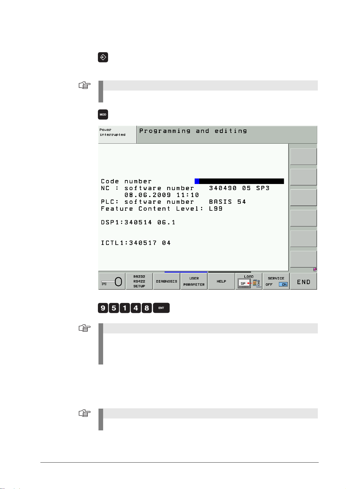
3.3 Input of Code Numbers
Note
Note
Note
8 If open: Close the program management by pressing the END button.
Pressing the MOD key while the program manager is open calls the interface settings.
8 Select the Programming and Editing operating mode.
8 Call the code number window.
8 Enter the code number and press ENT to confirm.
When certain code numbers are entered, new soft keys are displayed, MP EDIT,
PLC EDIT, OSCI.
With these soft keys you can also change to the corresponding areas without having to
enter the code number again.
When you have finished your work, reset all previously entered code numbers:
8 Enter the code number 0 and press ENT to confirm.
8 Press END to exit the code-number page.
All key codes are reset when the control is restarted.
3 – 18 HEIDENHAIN Service Manual iTNC 530
Page 19

Additional notes
As long as the machine parameter list is in the editor, no further code number can be
entered. First close the MP editor if you want to enter a new code number
After you have entered the code number for the machine parameters the PLC tree can be
seen in the program manager.
Only files with the extension .MP are displayed.
After entering the PLC code number all files in the PLC tree can be seen and loaded in the
editor.
However, to edit machine parameters, the soft key MP EDIT needs to be pressed first.
July 2010 3 – 19
Page 20

3 – 20 HEIDENHAIN Service Manual iTNC 530
Page 21

4Error Messages
Note
4.1 Introduction
iTNC features a comprehensive integral monitoring system for the prevention of input or
operation errors, as well as for identification and diagnosis of technical defects on the control
and the connected devices. The monitoring system is an integral component of the iTNC
hardware and software and is active as long as the control is switched on. The presence of a
technical fault or an operation error is made known through a plain-language message.
The effect of the monitoring functions is described in the annex -- .> See “Annex: Monitoring
Functions” on page 3 – 661.
Moreover, the machine manufacturer can define specific PLC error messages.
Type of error message
PLC error messages
Machine-specific error messages
Are defined by the machine manufacturer (e.g., coolant pump defective, protective door
open).
The machine manufacturer defines how the control reacts to a PLC error message (NC Stop,
EMERGENCY STOP, etc.).
The machine manufacturer defines whether the control can still be operated or has to be
rebooted after a PLC error message.
If you have any questions, please contact your machine manufacturer.
NC error messages
Are part of the HEIDENHAIN NC software.
Can be subdivided into error messages that result from operation, programming and machine
applications and those that indicate a technical defect (devices, electronic and mechanical
components, etc.)
HEIDENHAIN defines how the control reacts to an NC error message (NC Stop, EMERGENCY
STOP, etc.)
HEIDENHAIN defines whether the control can still be operated or has to be rebooted after an
NC error message.
If you have any questions, please contact your machine manufacturer and/or HEIDENHAIN.
Is the displayed error message an NC or PLC error message?
Display PLC error message NC error message
ERR window in the column
"Group".
Call -->
See “ERR Key” on page 4 – 26.
Log
Call -->
See “Log” on page 8 – 81.
There are no error numbers assigned to NC error messages that begin with N-1.
Operating-system error messages
Often contain the note CHILD PROCESS ERROR.
The control cannot be operated any more and has to be rebooted.
If you have any questions, please contact your machine manufacturer and/or HEIDENHAIN.
July 2010 4 – 21
PLC GENERAL
or
OPERATION
or
PROGRAMMING
P- (number and text of
error message)
N- (number and text of
error message)
Page 22
Display of the error message
All error messages that can be acknowledged with the CE key are …
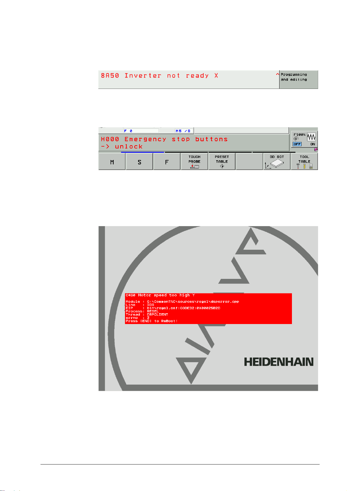
Displayed in the screen header (at the top of the screen) usually in red color.
As a plain-language message.
Figure: Error message in the header
The machine manufacturer can display additional information on PLC error messages in the
small PLC window (above the soft-key row).
Figure: Additional information in the small PLC window
Error messages that require a rebooting of the control ...
are displayed in a red or gray window (depending on the NC software version) in the center
of the screen.
are made known through a plain-language message.
Figure: Red error window
4 – 22 HEIDENHAIN Service Manual iTNC 530
Page 23

Figure: Gray error window
July 2010 4 – 23
Page 24

Reaction of control and machine
Display only
A message (info, warning, error) is only displayed.
The machine does not react. Programs are not stopped.
The error message can be acknowledged anytime.
Feed stop
The feed-rate enable is reset. The "F"symbol for the feed rate is highlighted.
The axes are braked at the nominal-value characteristic.
The contour of the workpiece is usually not damaged.
Once the error message is acknowledged, the machine continues to operate at the set feed
rate.
Program cancellation
The running NC progam is canceled.
The axes are braked at the nominal-value characteristic.
The contour of the workpiece is usually not damaged.
After the error message was acknowledged, the NC program needs to be restarted
(GOTO 0, NC-START).
NC stop
The running NC progam is stopped. The star "*" (STIB) flashes.
The axes are braked at the nominal-value characteristic.
The contour of the workpiece is usually not damaged.
After the error message was acknowledged, the NC program can be restarted at the position
where it was interrupted (NC-START key).
EMERGENCY STOP
Automatic generation of service files
An EMERGENCY STOP is triggered at the machine.
Axes and spindles decelerate at the current limit; the machine must be brought to a standstill
as quickly as possible.
The contour of the workpiece is not taken into account and may be damaged.
After the error message was acknowledged, the machine must be switched on completely.
Now, the PLC program can be restarted (GOTO 0, NC START).
RESET
An EMERGENCY STOP is triggered at the machine.
Axes and spindles decelerate at the current limit; the machine must be brought to a standstill
as quickly as possible.
The contour of the workpiece is not taken into account and may be damaged.
The error message cannot be acknowledged. The control must be shut down and restarted.
Now, the PLC program can be restarted (GOTO 0, NC START).
As of NC software version 340 49x-04:
In the event of serious NC software errors or PLC error messages especially defined for this
purpose service files are generated automatically.
See “Creating and Downloading of Service Files” on page 7 – 77.
4 – 24 HEIDENHAIN Service Manual iTNC 530
Page 25
4.2 HELP Key
Note
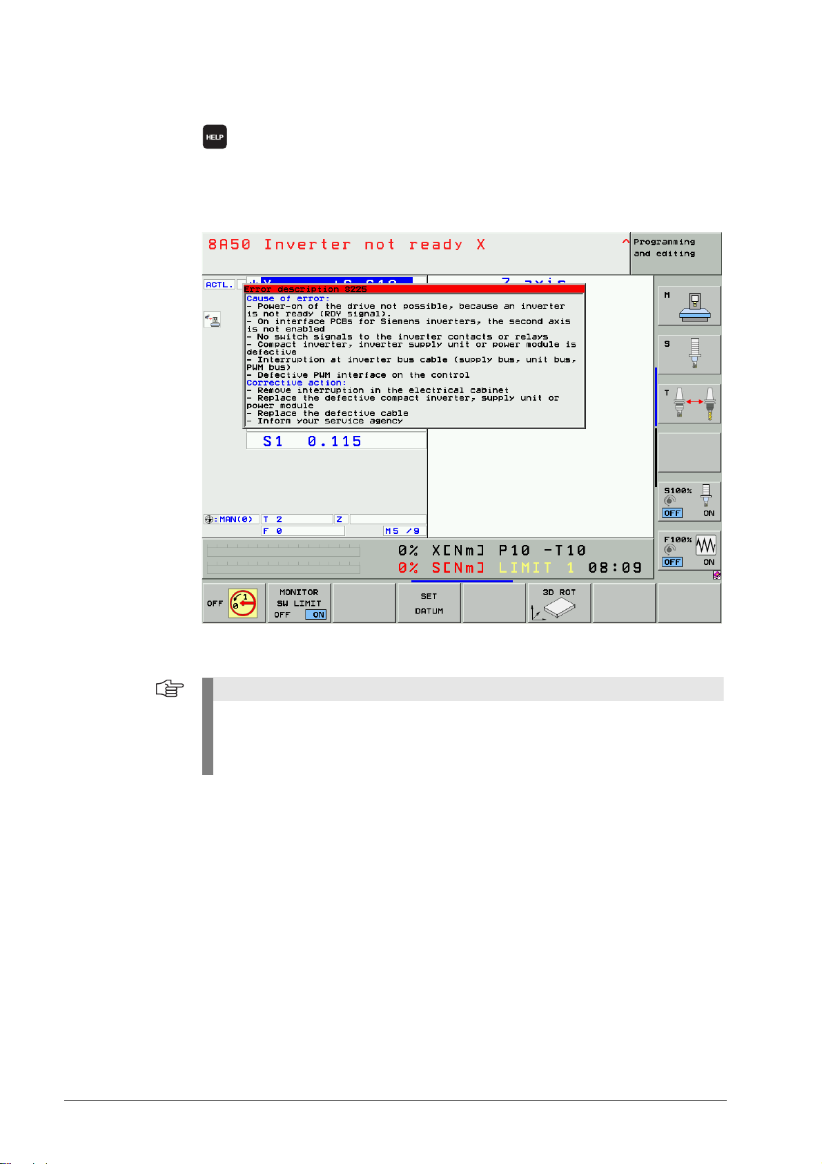
8 Display help texts for error messages
(If you press this key again, the window will close.)
If the service technician presses the HELP key a window is shown that describes the cause
of error and possibilities of corrective action in addition to the displayed error message.
This support can also be realized for PLC error messages by the machine manufacturer!
Figure: HELP window
HELP texts cannot be displayed for error messages in red or gray windows. The control
must be rebooted.
Information on these errors can be found in the list of NC error messages, See “List of NC
Error Messages” on page 4 – 29.
July 2010 4 – 25
Page 26

4.3 ERR Key
Note
8 Display all pending error messages in a list
(If you press this key again, the window will close.)
If there is an AND symbol (little red roof) in the header in addition to the error message, there is
more than one pending error message.
The ERR key (ERROR) is located directly over the HELP key. When this key is pressed all
pending NC and PLC error messages of the control are displayed in an own window.
List of error messages
In the ERR window In the log
In order of priority In chronological order
Errors with a higher priority are at the top of
the list.
The log is written from top to bottom, i.e.,
older errors are at the top, younger errors at
the bottom.
In addition, the help window can be called with the HELP key.
If your machine still features an old keyboard without an ERR key over the HELP key, press
the respective "space key" over the HELP key. --> If the NC software of the iTNC 530
supports the function of the ERR key, it can also be used to call the ERR list!
4 – 26 HEIDENHAIN Service Manual iTNC 530
Page 27

The columns in the ERR window have the following meanings:
Column Description
Number Error number (–1: no error number defined), issued by HEIDENHAIN or your
machine tool builder
Class Error class. Defines the reaction of the control:
ERROR
Program run is interrupted by the iTNC
FEED HOLD
The feed-rate release is canceled
PGM HOLD
The program run is interrupted (the control-in-operation symbol blinks)
PGM ABORT
The program run is interrupted (INTERNAL STOP)
EMERG. STOP
EMERGENCY STOP is set off
RESET
iTNC executes a system restart
WARNING
Warning message, program run resumes
INFO
Info message, program run resumes
Group Error source.
GENERAL
General error
OPERATING
Error during machining and machine traverse
PROGRAMMING
Error during programming
PLC
PLC error message of the machine manufacturer
Error
message
Displayed error text
The individual error messages can be selected with the cursor; the open help window shows
the appertaining text.
July 2010 4 – 27
Page 28

4.4 CE Key
Note
8 Clear error message (Clear Error)
Acknowledge error messages displayed by pressing the CE key.
If the error cause is still existing, the corresponding error message is displayed again. -->
Eliminate the error!
Messages regarding very fatal errors, cannot be confirmed with the CE key.
The control must be rebooted.--> Press the END key.
If this does not work --> Switch the power switch of the machine off and wait for several
seconds before you switch it on again.
4 – 28 HEIDENHAIN Service Manual iTNC 530
Page 29

4.5 List of NC Error Messages
Complete list You can find the complete list of all NC error messages (including operator errors) on the
TNCguide DVD in several languages and sorted by error numbers.
This TNCguide information is also available on our website --> www.heidenhain.de/...
This is the official list of NC error messages which contains all possible errors of HEIDENHAIN
controls that operate with the HeROS operating system.
It consists primarily of error messages related to operation and handling as well as technical error
messages.
Filtered list The list below contains the most important error messages that indicate a technical defect
in numerical and subsequently in alphabetical order.
A reference is made, if there are additional descriptions in this Service Manual.
Error message Possible cause of error Measures for error diagnosis and/or
corrective action
8040 Heat-sink
temp. UV 1xx
8041 Excessive Iz
in UV 1xx
8043 No inverterready signal
8060 Leakage
current in UV 1xx
Additional information and descriptions in
the manual
Heat-sink temperature of UV 1xx power
supply unit is too high.
If the heat-sink temperature continues to
increase, the unit will be switched off.
See “Status of HEIDENHAIN inverters” on
page 3 – 682.
DC-link current of UV 1xx power supply unit
too high
See “Status of HEIDENHAIN inverters” on
page 3 – 682.
Readiness signal of the inverter (supply unit)
is inactive after the feedback control starts.
Master contactor has opened.
Error in PLC program
Inverter defective
See “Status of HEIDENHAIN inverters” on
page 3 – 682.
Insulation problem (e.g. defective motor). Check the motor.
Additional information and descriptions in
the manual
Stop the machine and let it cool down.
Continue working with lower power (reduce
the feed rate).
See Service Manual Inverter Systems and
Motors
Continue working with lower power (reduce
the feed rate).
See Service Manual Inverter Systems and
Motors
Try to restart.
Check the wiring (master contactor).
Check the PLC program.
Exchange the inverter (supply unit).
See “Checking the readiness of the inverter
system” on page 16 – 243.
See Service Manual Inverter Systems and
Motors.
Check the wiring.
See “Status of HEIDENHAIN inverters” on
page 3 – 682.
8061 No inverterready signal
July 2010 4 – 29
Readiness signal of the inverter (supply unit)
is inactive after the feedback control starts.
Master contactor has opened.
Error in PLC program
Inverter defective
See “Status of HEIDENHAIN inverters” on
page 3 – 682.
See Service Manual Inverter Systems and
Motors.
Try to restart.
Check the wiring (master contactor).
Check the PLC program.
Exchange the inverter (supply unit).
See “Checking the readiness of the inverter
system”
See Service Manual Invert
Motors.
on page 16 – 243.
er Systems and
Page 30

Error message Possible cause of error Measures for error diagnosis and/or
corrective action
8080 Uz UV 1xx
too high
8092 Pos. contr.
cyc. time error
8130 Motor brake
defective <axis>
8140 Error <axis>
field orientation
Additional information and descriptions in
the manual
DC-link voltage of the power supply unit too
high.
See “Status of HEIDENHAIN inverters” on
page 3 – 682.
MC is outputting erroneous cycle time for
CC position controller.
Hardware error
Motor brake defective. Traverse the axis to a safe position before
Field orientation impossible for mechanical
reasons.
Incorrect relation between electrical field
and mechanical motor motion.
Incorrect motor encoder signal.
Incorrect motor connection.
Mechanical brakes not released.
Additional information and descriptions in
the manual
Check the configuration datum (braking of
the spindle).
Check the braking resistor.
Replace the power supply unit.
See Service Manual Inverter Systems and
Motors.
Check machine parameter 7600.x.
Exchange the drive control board.
power-off.
Check controls for motor brakes.
Exchange the motor.
See “Controlling the motor brakes” on page
3 – 684.
See Service Manual Inverter Systems and
Motors.
Check the machine parameters for number
of signal periods and distance for the
number of signal periods.
Check the machine parameter for the linear
distance of one motor revolution.
For linear motors: Check STR column of the
motor table.
Check the speed encoder connection.
Check the motor connection.
Release brakes during orientation.
8300 Motor brake
defective <axis>
831
0 No current in
brake test <axis>
See “Speed Encoders” on page 18 – 293. See “Sequence for Finding Errors in the
Control Loop” on page 6 – 62.
See “Speed Encoders” on page 18 – 293.
See Service Manual Inverter Systems and
Motors.
Motor brake defective. Traverse the axis to a safe position before
power-off.
Check controls for motor brakes.
Exchange the motor.
See “Controlling the motor brakes” on page
3 – 684.
Manual Inverter Systems and
Motor connected incorrectly
Inverter connected incorrectly
Inverter defective
Motor defective
See Service
Motors.
Check the wiring of motor and inverter.
Check the inverter.
Check the motor.
See “Controlling the motor brakes” on page
3 – 684.
See Service Manual Inverter Systems and
Motors.
4 – 30 HEIDENHAIN Service Manual iTNC 530
Page 31

Error message Possible cause of error Measures for error diagnosis and/or
corrective action
8610 I2T value is
too high <axis>
8620 Load is too
high <axis>
8640 I2T value of
motor is too high
<axis>
Additional information and descriptions in
the manual
Excessive load over the time of the drive. Reduce the load or the duration.
See “I2t monitoring” on page 3 – 676. See Service Manual Inverter Systems and
Drive has maximum current and cannot
accelerate.
Excessive load (torque, power) on the drive.
The load of the motor is too high over the
duration.
Additional information and descriptions in
the manual
Check the motor table, power stage table
and configuration data.
Check whether the motor and power
module are designed for the load.
Motors.
Reduce the load on the drive.
Check the motor table, power stage table
and machine parameters.
Check whether the motor and power
module are designed for the load.
See “Sequence for Finding Errors in the
Control Loop” on page 6 – 62.
See Service Manual Inverter Systems and
Motors.
Reduce the load or the duration.
Check the motor table and machine
parameters.
Check whether the motor is designed for
the load.
8650 I2T value of
motor is too high
<axis>
8800 Signal LTRDY inactive
<axis>
8810 Signal LTRDY inactive
<axis>
8820 Field angle
unknown <axis>
See “I2t monitoring” on page 3 – 676. See Service Manual Inverter Systems and
Motors.
The load of the power module is too high
over the duration.
See “I2t monitoring” on page 3 – 676. See Service Manual Inverter Systems and
Inverter switch-off during closed-loop
control of a vertical axis (cause = vertical
axis).
See “Status of HEIDENHAIN inverters” on
page 3 – 682.
Inverter switch-off during closed-loop
control of a vertical axis (cause = vertical
axis).
See “Status of HEIDENHAIN inverters” on
page 3 – 682.
Field angle of the motor on the reference
point of the speed encoder has not yet been
ascertained.
Reduce the load or the duration.
Check the motor table and machine
parameters.
Check whether the power module is
designed for the load.
Motors.
Check the PLC program.
Check the wiring of the inverter.
See Service Manual Inverter Systems and
Motors.
Ch
eck the PLC program.
Check the wiring of the inverter.
See Service Manual Inverter Systems and
Motors.
Run a field orientation.
Check the motor table (column SYS).
See “Speed Encoders” on page 18 – 293.
July 2010 4 – 31
Page 32

Error message Possible cause of error Measures for error diagnosis and/or
corrective action
8830 EnDat: No
field angle <axis>
8860 Input
frequency from
speed encoder
<axis>
8870 Input
frequency from
position encoder
<axis>
8A00 No inverter
enabling %.2s
Additional information and descriptions in
the manual
Field angle of the motor with unaligned
speed encoder with EnDat interface has not
been ascertained.
The transferred EnDat serial number does
not match the stored EnDat serial number.
Connected EnDat encoder or encoder cable
is defective.
Noise on speed encoder signals Check the encoder signals.
Noise on position encoder signals Check the encoder signals.
Power-on of the drive not possible due to
missing enabling of the inverter via –SH1.
Additional information and descriptions in
the manual
Run a field orientation.
Check the motor table (column SYS).
See “Speed Encoders” on page 18 – 293.
Check the shielding.
See “Further Examination of Position and
Speed Encoders” on page 18 – 308.
Check the shielding.
See “Further Examination of Position and
Speed Encoders” on page 18 – 308.
Check the wiring.
8A10 AC fail %.2s Power-on of the drive not possible, because
an AC-fail signal (power supply) is active.
8A20 Powerfail
%.2s
8A30 Drive
enabling (I32)
%.2s
Power-on of the drive not possible, because
a powerfail signal (power supply) is active.
Power-on of the drive not possible due to
missing drive enabling via I32.
See “Checking the readiness of the inverter
system” on page 16 – 243.
See Service Manual Inverter Systems and
Motors
Test the power supply.
Check the wiring of the power supply.
See Service Manual Inverter Systems and
Motors
Test the power supply.
Check the wiring of the power supply.
See Service Manual Inverter Systems and
Motors
Check the wiring of the emergency-stop
loop.
See “Checking the global drive enable I32,
connector X42 / pin 33” on page 16 – 239.
4 – 32 HEIDENHAIN Service Manual iTNC 530
Page 33

Error message Possible cause of error Measures for error diagnosis and/or
corrective action
8A40 Enabling of
axis group %.2s
8A50 Inverter not
ready %.2s
8AF0 Encoder
<axis> defective
Additional information and descriptions in
the manual
Because of missing drive enabling for axis
groups (X150/X151), the drive cannot be
switched on.
Power-on of the drive not possible, because
an inverter is not ready (RDY signal).
Contamination of the position encoder
Encoder cable defective
Motor control board defective
See “Position Encoders” on page 18 – 277. See “Position Encoders” on page 18 – 277.
Additional information and descriptions in
the manual
Check the connector on X150/X151 for
correct fit.
Check the wiring of X150/X151.
Check MP2040.x.
See “Checking the drive enabling for the
axis groups via connector X150 and X151 (if
wired)” on page 16 – 242.
Check the Ready LED of the inverter.
Check the wiring of the inverter.
On interface PCBs for Siemens inverters,
the second axis is not enabled.
See “Checking the readiness of the inverter
system” on page 16 – 243.
See Service Manual Inverter Systems and
Motors.
Exchange position encoder.
Check encoder cable.
Exchange the motor drive control board.
8B00 <Achse>
motor encoder
defective
8B00 Zn track
%.2s error
8B10 Wrong
traverse direction
<axis>
No encoder signal available.
Interruption in motor encoder cable.
Signal amplitude of motor encoder is
missing or too small.
See “Speed Encoders” on page 18 – 293. See “Speed Encoders” on page 18 – 293.
Contamination of the motor encoder
(Zn track)
Motor encoder cable is defective.
Motor control board is defective.
See “Speed Encoders” on page 18 – 293. See “Speed Encoders” on page 18 – 293.
DIR entry in motor table is incorrect.
Incorrect motor power connection.
Check connection of motor encoder.
Check the motor encoder.
Check the amplitude of the encoder signal.
Exchange the motor.
Check the motor encoder cable.
Exchange the motor drive control board.
Check the DIR entry in the motor table.
eck the motor power connection.
Ch
See Service Manual Inverter Syst
Motors.
ems and
July 2010 4 – 33
Page 34

Error message Possible cause of error Measures for error diagnosis and/or
corrective action
8B20 Error <axis>
field orientation
8B30 Motor
temperature
%.2s too high
Additional information and descriptions in
the manual
Field orientation impossible for mechanical
reasons.
Incorrect relation between electrical field
and mechanical motor motion.
Incorrect motor encoder signal.
Incorrect motor connection.
Mechanical brakes not released.
See “Speed Encoders” on page 18 – 293. See “Sequence for Finding Errors in the
Measured motor temperature is too high.
No temperature sensor
Motor encoder cable is defective (wire
broken).
Entry in motor table is incorrect.
Incorrect or defective temperature sensor
was installed.
Additional information and descriptions in
the manual
Check the machine parameters for number
of signal periods and distance for the
number of signal periods.
Check the machine parameter for the linear
distance of one motor revolution.
For linear motors: check column STR of the
motor table.
Check the speed encoder connection.
Check the motor connection.
Release brakes during orientation.
Control Loop” on page 6 – 62.
See “Speed Encoders” on page 18 – 293.
See Service Manual Inverter Systems and
Motors.
Let the motor cool down.
Check the motor encoder cable.
Check the entry in the motor table.
Measure the temperature sensor (576
[Ohm] at 20 [°C]).
See “Speed Encoders” on page 18 – 293.
See Service Manual Inverter Systems and
Motors.
See “Speed Encoders” on page 18 – 293.
See Service Manual Inverter Systems and
Motors.
4 – 34 HEIDENHAIN Service Manual iTNC 530
Page 35

Error message Possible cause of error Measures for error diagnosis and/or
corrective action
8B40 No drive
enabling %.2s
Additional information and descriptions in
the manual
Inverter is not ready for operation.
No pulse release for the power module.
Uz too high
Power-fail signal is active.
With M controls: I32 input inactive
With P controls: Drive release at X50
inactive
In addition, for 246 261-xx (digital current
controller):
For the given axis an illegal motor model
(e.g. linear motor) was selected.
The CC receives a "Drive on" command for a
nonexistent axis.
The power module is not ready when the
field orientation starts.
Readiness of the power module is detected
through the Ready signal on the PWM cable.
The power module is not ready when the
current controller adjustment begins.
Motor control board defective
PWM cable defective
Noise pulses
Additional information and descriptions in
the manual
Check the activation and wiring of the pulse
release.
Check Uz.
Check the emergency stop circuit.
For a non-regenerative system: Is the
braking resistor connected?
For a regenerative system: Is the energy
recovery activated?
Check the grounding and shielding of the
cable.
Exchange the power module.
For SIEMENS power converter (inverter):
Exchange the interface card.
Exchange drive control board.
Check the control and cabling of the pulse
release.
8B50 Axis module
%.2s not ready
No pulse release for the power module
Uz too high
5-V power supply too weak
Inverter not ready for operation
Motor control board defective
PWM cable defective
Noise pulses
See “Checking the Enables on the iTNC
530” on page 16 – 229.
See Service Manual Inverter Systems and
Motors.
Check the control and cabling of the pulse
release.
Check Uz.
If the power supply is not regenerative: Is
the braking resistor connected?
If the power supply is regenerative: Is the
energy recovery activated?
Check the grounding and shielding of the
cable.
Exchang
For P controls: Exchange the interface card.
Exchange
See “Checking the Enables on the iTNC
530” on page 16 – 229.
See Service Manual Inverter Systems and
Motors.
e the power module.
the motor drive control board.
July 2010 4 – 35
Page 36

Error message Possible cause of error Measures for error diagnosis and/or
corrective action
8B60 Overcurrent
cutoff %.2s
8BA0 Incorrect
reference signal or
line count %.2s
Additional information and descriptions in
the manual
Undervoltage, temperature, or short-circuit
monitor of an IGBT in the inverter has
responded.
Invalid entry for the line count STR in the
motor table
Faulty reference signal
Noise pulses
Motor encoder cable defective (break or
short circuit)
Additional information and descriptions in
the manual
Let the inverter cool down.
Check the motor connection for a short
circuit.
Examine the motor for short circuit in the
windings.
Exchange the power module.
See “Sequence for Finding Errors in the
Control Loop” on page 6 – 62.
See Service Manual Inverter Systems and
Motors.
Check the entry in the motor table.
Check the signals from the speed or
rotational speed encoder (PWM8).
Check encoder cable for interruption or
short circuit under mechanical load
(bending, stretching, etc.).
Check the shielding and shield connection in
the encoder cable.
Exchange encoder cable.
Exchange the motor.
See “Speed Encoders” on page 18 – 293.
See Service Manual Inverter Systems and
Motors.
8BB0 Motor
temp. too low
%.2s
8BC0 Motor
current %.2s too
high
Measured motor temperature too low
Temperature sensor wired incorrectly (short
circuit)
Temperature sensor defective
Incorrect temperature sensor (KTY84
required)
Hardware error on encoder input PCB
Incorrect motor or power module selected
Incorrect current controller parameters
Incorrect parameters in the motor table
Power module defective
Motor cable defective (short circuit).
Motor defective (short circuit, ground fault)
Motor control boar
d defective
Check the wiring.
Check temperature sensor.
Deselect monitoring of excessively low
temperature with MP2220 bit 5.
Exchange encoder input PCB.
See “Speed Encoders” on page 18 – 293.
See Service Manual Inverter Systems and
Motors.
Correct
Check the current control adjustment.
Check the motor and motor cable for a short
circuit.
Exchange the power module or the drive
control board.
See “Sequence for Finding Errors in the
Control Loop” on page 6 – 62.
See Service Manual Inverter Systems and
Motors.
motor and power module selected?
4 – 36 HEIDENHAIN Service Manual iTNC 530
Page 37

Error message Possible cause of error Measures for error diagnosis and/or
corrective action
8BD0 Excessive
servo lag in <axis>
8BE0 Encoder
defective <axis>
Additional information and descriptions in
the manual
The following error of a moving axis is
greater than the value given in machine
parameter MP1720.x (in lag mode) or MP
1420.x (feedforward mode).
The acceleration entered is too large.
The motor is not moving even though drive-
on was given.
Overloaded driver
Insufficient lubrication
Mechanical stiffness
Machine vibration
Hardware error in the control loop
For analog axes: servo defective
Incorrect nominal distance between two
reference marks
Additional information and descriptions in
the manual
Reduce the feed rate and increase the
spindle speed.
Remove potential sources of vibration.
The motor current must not be limited
during acceleration.
Check the lubrication.
Remove mechanical stiffness.
Analog axes: Check the servo.
Check the acceleration.
See “Sequence for Finding Errors in the
Control Loop” on page 6 – 62.
Carry out offset adjustment (See “Adjusting
the electrical offset (drift adjustment)” on
page 20 – 349).
Carry out speed adjustment (See “Speed
adjustment at the servo amplifier
(tachometer adjustment)” on page 20 –
352).
Check the entry in the motor table and
MP2206.x.
Check the entry in MP334.x.
Check if the reference signal is disturbed.
8BF0 Input
frequency from
speed encoder
<axis>
8C00 Input
frequency from
position encoder
<axis>
8C10 <axis>
motor encoder
defective
A080 CC%d
operating state
not equal MC
See “Encoder Interface” on page 18 – 277.
Noise on speed encoder signals Check the encoder signals.
Check the shielding.
See “Further Examination of Position and
Speed Encoders” on page 18 – 308.
Noise on position encoder signals Check the encoder signals.
Check the shielding.
See “Further Examination of Position and
Speed Encoders” on page 18 – 308.
No encoder signal available
Interruption in motor encoder cable
Signal amplitude of motor encoder is
missing or too small.
The automatic SRG, SBH, and SH operating
states of the MC and CC are compared
cyclically. If the values remain unequal for
longer than 500 ms, a Stop 1 is released.
Check connection of motor encoder.
Check the motor encoder.
Check the amplitude of the encoder signal.
See “Speed En
See Service Manual Inverter Systems and
Motors.
Press CE to acknowledge the error
message.
Switch on the machine.
Check the software version.
coders” on page 18 – 293.
July 2010 4 – 37
Page 38

Error message Possible cause of error Measures for error diagnosis and/or
corrective action
AC00 CC
amplitude too high
%.2s
8B00 <Achse>
motor encoder
defective
AC20 CC
frequency too
high %.2s
Additional information and descriptions in
the manual
The amplitude of the encoder signal is too
high or the signal for contamination is active.
Noise on motor encoder signal
Short-circuit in motor encoder cable
Motor encoder signal amplitude too high
Noise on signal
Scanning head too close to scale
For very old encoders: Incandescent lamp
too bright (spiral-wound filament shortcircuited)
No encoder signal available
Interruption in motor encoder cable
Signal amplitude of motor encoder is
missing or too small.
The maximum input frequency was
exceeded at an encoder input.
Noise on motor encoder signal
Additional information and descriptions in
the manual
Check connection of motor encoder (ground
connection).
Check the motor encoder.
Adjust the scanning head.
See “Encoder Interface” on page 18 – 277.
Check connection of motor encoder.
Check the motor encoder.
Check the amplitude of the encoder signal.
See “Speed Encoders” on page 18 – 293.
Check connection of motor encoder (ground
connection).
Check the motor encoder.
Check encoder signal input frequency.
AC40 CC ampl.
too low %.2s
(position)
AC50 CC freq. too
high %.2s
(position)
The position encoder signal amplitude is too
small or the contamination signal is active.
Interruption in encoder cable.
Encoder signal amplitude missing.
The maximum input frequency was
exceeded at a position encoder input.
Noise on the encoder signal
See “Speed Encoders” on page 18 – 293.
Check connection of encoder.
Check the encoder.
Check encoder signal amplitude.
Inform your service agency.
See “Encoder Interface” on page 18 – 277.
Check connection of encoder (ground
connection).
Check the encoder.
Check the input frequency of the encoder
signal.
See “Further Examination of Position and
Speed Encoders” on page 18 – 308.
4 – 38 HEIDENHAIN Service Manual iTNC 530
Page 39

Error message Possible cause of error Measures for error diagnosis and/or
corrective action
B900 CC%d
supply voltage %d
BA00 CC%d
operating
temperature %d
Additional information and descriptions in
the manual
The Vcc supply voltage (x) was out of range.
+4 = Undervoltage Vcc (+5 V)
Excessive load from external components
(e.g. encoders).
+6 = Overvoltage Vcc
(+5 V).
The power supply unit is defective.
+14 = Undervoltage Vcc (+15 V)
The power supply unit is defective.
+16 = Undervoltage Vcc (+15 V)
The power supply unit is defective.
-14 = Overvoltage Vcc
(-15 V).
The power supply unit is defective.
-16 = Overvoltage Vcc
(-15 V).
The power supply unit is defective.
The temperature inside the LE was out of
the permissible range. (-128... 0...+127 =
Measured temperature value [°C] )
Temperature sensor on PCB is defective.
Insufficient ventilation of the electrical
cabinet (fan defective).
The ambient temperature is too high or too
low.
Additional information and descriptions in
the manual
Measure supply voltage Vcc (x).
Vcc (+5 V) < +4.75 V Check encoder
connections.
Vcc (+5 V) > +5.50 V Exchange power
supply unit.
Vcc (+15 V) < +14.25 V Exchange power
supply unit.
Vcc (+15 V) > +16.50 V Exchange power
supply unit.
Vcc (-15 V) < -14.25 V Exchange power
supply unit.
Vcc (-15 V) > -16.50 V Exchange power
supply unit.
See “Power Supply” on page 17 – 251
Check the ventilation conditions.
C003 MC/CC%d
system clock
mismatch
C004 Undefined
interrupt
C005 Unknown
hardware
identifier
C007 DC-link
voltage too low
C00A PWM
triangular signal
error
Hardware error (quartz generator)
Software error
Software error
Hardware error: Disturbance results in
internal interrupt
Software does not fit the hardware.
Hardw
Inverter defective
Line power interrupted
Hardware error: Triangular signal does not
are defective
oscillate or it oscillates at the wrong
frequency
See “Information Menu” on page 17 – 267
See “Annex: Monitoring Functions” on page
3 – 661
See “Temperature” on page 6 – 75
Exchange the drive control board or
processor board.
Check the software version.
Switch off the machine.
Switch on the machine.
Check the software version.
Check the grounding.
Check the software
Exchange drive control board.
Check your line power supply.
Check the inverter.
See Service Manual “Inverter Systems and
Motors“
Exchange drive control board.
Inform your service agency.
version.
July 2010 4 – 39
Page 40

Error message Possible cause of error Measures for error diagnosis and/or
corrective action
C00B Too little
main memory
C00D Program
checksum error
C00E Controller
software timeout
C012 Pos. control
err. Cycle time
C016 Double
speed not
possible
C017 PWM
frequency too
high
Additional information and descriptions in
the manual
Internal software error Check the software version.
Internal software or hardware error Check the software version.
Internal software or hardware error Check the software version.
MC is outputting erroneous cycle time for
CC position controller.
Hardware error
Control loop on X51 or X52 is defined as
"double speed," although the control loop on
X53 or X54 is active.
Control loop on X55 or X56 is defined as
"double speed," although the control loop on
X57 or X58 is active (only CC 4xx with 8
control loops).
For a single-speed control loop, the PWM
basic frequency set in MP2180.x is twice as
high, and the current controller cycle time
set in MP2182.x is half as high.
Additional information and descriptions in
the manual
Exchange drive control board.
Exchange drive control board.
Inform your service agency.
Check machine parameter 7600.0
Exchange drive control board.
Define the control loop on X51 or X52 as
"single speed," or deactivate the PWM
output X53 or X54
Define the control loop on X55 or X56 is
defined as "single speed," or deactivate the
PWM output X57 or X58 (only CC 4xx with 8
control loops).
Check MP2180.x and MP2182.x.
Use a double-speed control loop instead of
single-speed.
C018 Masterslave torque: Axis
assignment
incorrect
C2A0 Encoder
input %.2s
C300 Zn track
%.2s error
C310 Z1 track
%.2s error
Axes in master-slave torque control are only
permitted at X15/X17 or X16/X18.
Incorrect entry in MP112.x or MP113.x
(speed encoder).
Internal software error
No encoder signal available
Interruption in motor encoder cable
Signal amplitude of motor encoder is
missing or too small.
See “Speed Encoders” on page
Contamination of the motor encoder (Z1
track)
Motor encoder cable is defective.
Motor control board is defective.
See “Speed Encoders” on page 18 – 293 See “Speed Encoders” on page 18 – 293
18 – 293 See “Speed Encoders” on page 18 – 293
Change the axis assignment.
Check the entry in MP112.x or MP113.x.
Check the software version.
Check connection of motor encoder.
Check the motor encoder.
Check the amplitude of the encoder signal.
Exchange the motor.
Check the motor encoder cable.
Exchange the motor drive control board.
4 – 40 HEIDENHAIN Service Manual iTNC 530
Page 41

Error message Possible cause of error Measures for error diagnosis and/or
corrective action
C330 Motor temp.
too high %.2s
C340 Unknown
counter compnt.
%.2s
Axis module %.2s
not ready
Additional information and descriptions in
the manual
Measured motor temperature is too high.
No temperature sensor
Motor encoder cable is defective.
Entry in motor table is incorrect.
Incorrect or defective temperature sensor
was installed.
See “Speed Encoders” on page 18 – 293.
See Service Manual Inverter Systems and
Motors.
Hardware defective
Motor encoder defective
Incorrect software version
No pulse release for the power axis module
Uz too high
5-V power supply too weak
Inverter not ready for operation
Motor control board defective
PWM cable defective
Noise pulses
Additional information and descriptions in
the manual
Let the motor cool down.
Check the motor encoder cable.
Check the entry in the motor table.
Measure the temperature sensor.
See “Speed Encoders” on page 18 – 293.
See Service Manual Inverter Systems and
Motors.
Check the software version.
Operate the motor at another encoder input.
Exchange drive control board.
Check the control and cabling of the pulse
release.
Check Uz.
If the power supply is not regenerative: Is
the braking resistor connected?
If the power supply is regenerative: Is the
energy recovery activated?
Check the grounding and shielding of the
cable.
Exchange the power module.
For P controls: Exchange the interface card
Exchange the motor drive control board.
C370 Angle error
motor enc. %.2s
C380 Motor %.2s
t controllable
no
C390 Error in 3-D
touch probe %.2s
Motor encoder defective
Motor encoder cable defective
Drive control board defective
Motor cables crossed (e.g. X with Y).
Motor encoder cables crossed
Phases connected incorrectly to motor
Motor encoder cable defective
Incorrect motor table entry (direction of
rotation)
Motor defective
I2t monitoring has responded.
See “Speed Encoders” on page 18 – 293.
See Service Manual Inverter Systems and
Motors.
Software error
Hardware error in drive control board
See “Checking the Enables on the iTNC
530” on page 16 – 229.
See Service Manual Inverter Systems and
Motors.
Check the motor encoder and leads.
Exchange the motor control board.
See “Speed Encoders” on page 18 – 293.
Check the motor cabling.
Check motor and motor encoder cabling.
Check motor table entry.
Check I2t monitoring (MP2302.x).
See “Speed Encoders” on page 18 – 293.
See Service Manual Inverter Systems and
Motors.
Exchange the motor drive control board.
Check the software version.
See “Touch Probe” on page 25 – 413.
July 2010 4 – 41
Page 42

Error message Possible cause of error Measures for error diagnosis and/or
corrective action
C3A0 Incorrect
ref. position %.2s
C3B0 Motor
%.2s: is not
turning
Additional information and descriptions in
the manual
Incorrect motor selected (MP2200)
Grounding error on motor encoder cable
(disturbance on reference signal line)
Motor encoder defective
Inverter is not ready for operation.
Disturbance on RDY input of PWM output
connector
Motor jammed
Inverter defective
Motor defective
Incorrect motor selected (MP2200.x).
Assignment of PWM outputs incorrectly
entered in MP120.x.
Assignment of encoder inputs incorrectly
entered in MP112.x
Motor power cables crossed
Motor encoder cables crossed
Motor connection defective
I2T monitoring is responding
Additional information and descriptions in
the manual
Check the motor selection (MP2200)
Check the cabling of the motor encoder
(grounding).
Exchange the motor.
See “Speed Encoders” on page 18 – 293.
Check the inverter.
Check the motor and cabling.
Check the machine parameters.
Check I2t monitoring (MP2302.x).
C3C0 Motor
current %.2s too
high
C3D0 PWM
component
defective %.2s
C3E0 Err. in rated
U of motor %.2s
C3F0 EnDat not
found <axis>
See “Sequence for Finding Errors in the
Control Loop” on page 6 – 62.
See Service Manual Inverter Systems and
Motors.
Incorrect current controller parameters.
Incorrect parameters in the motor table.
Power module defective.
Motor cable defective.
Motor defective.
Motor control board defective.
An internal hardware error has occurred. Infor
Motor rated voltage outside of permitted
input range
Connected EnDat encoder or encoder cable
is defective.
EnDat communication error
Correct motor and power module selected?
Check the current control adjustment.
Check the motor and motor cable for a short
circuit.
Exchange the power module or drive control
board.
See “Sequence for Finding Errors in the
Control Loop” on page 6 – 62
See Service Manual Inverter Systems and
Motors
Exchange dr
Check the entry in the motor table.
Check the motor table (column SYS).
Exchange the motor drive control board.
Check speed encoder cable (defective or too
long).
Check speed encoder.
Check the grounding and shielding of the
cable.
m your service agency.
ive control board.
See “Speed Encoders” on page 18 – 293.
4 – 42 HEIDENHAIN Service Manual iTNC 530
Page 43

Error message Possible cause of error Measures for error diagnosis and/or
corrective action
C400 Line count
error <axis>
C410 Rotor
position <axis>
undefined
C430 Ctrlr
parameters
incorrect %s
Additional information and descriptions in
the manual
Line count from the motor table does not
match the downloaded values.
See “Speed Encoders” on page 18 – 293. See “Speed Encoders” on page 18 – 293.
Contamination of the speed encoder (Zn
track).
Speed encoder cable defective.
Motor control board defective.
Speed encoder defective.
See “Speed Encoders” on page 18 – 293. See “Speed Encoders” on page 18 – 293.
Feedforward-control parameters are set
incorrectly (acceleration, friction).
Excessive acceleration.
Controller parameters are set incorrectly (Ki,
Kp, Kd).
Filters set incorrectly (band rejection, low
pass).
Inverter defective (IGBT).
Incorrect motor selected in motor table.
Additional information and descriptions in
the manual
Check machine parameter
(distance of one motor revolution and
distance for the number of signal periods).
Check the motor table (columns TYPE and
STR).
Check speed encoder.
Exchange the motor.
Check the speed encoder cable.
Exchange the motor drive control board.
Check the adjustment of the axes.
Check the inverter.
C430 Error of
position input
<axis>
C440 PWM
frequency <axis>
incorrect
C450 Wrong
encoder <axis>
Position encoder input does not exist.
Position encoder input not connected
correctly.
Position encoder input defective.
PWM frequency within a control group is
incorrect.
Entry in column SYS of the motor table
incorrect.
Speed encoder cable defective.
Speed encoder defective.
Motor control board defective.
See “Sequence for Finding Errors in the
Control Loop” on page 6 – 62.
See Service Manual Inverter Systems and
Motors.
Install position encoder input.
Check connection of the position encoder
input.
Exchange position encoder input.
See “Position Encoders” on page 18 – 277.
Check the machine parameters for PWM
frequency.
PWM frequency > 5000 Hz only with
suitable hardware and only with PWM
outputs X51, X52, X57 or X58.
PWM freque
identical within the control group.
PWM frequency > 3200 Hz
Check the motor table (column SYS).
Check the speed encoder cable.
Exchange the motor.
Exchange the motor drive control board.
ncy <= 5000 Hz must be
See “Speed Encoders” on page 18 – 293. See “Speed Encoders” on page 18 – 293.
C460 Motor
speed too high
<axis>
July 2010 4 – 43
Motor not controllable Check the software version.
Inform your service agency.
Page 44

Error message Possible cause of error Measures for error diagnosis and/or
corrective action
C4A0 Inverter %s
is not active
C4C0 No motor
current %s
C5F0 Wrong
position-encod.
input
Additional information and descriptions in
the manual
Inverter switched off (PLC, SH1)
Inverter defective
Motor defective
Incorrect motor selected in motor table
Motor connected incorrectly
Motor power cables crossed
Motor connected incorrectly or not at all
Inverter defective
Motor defective
Incorrect motor selected in motor table
Motor power cables crossed
Conductor bars not tightened sufficiently. Tighten the conductor bars securely.
An incorrect input was selected for the
position encoder (MP110.x/MP111.x)
Possible configurations: CC4xx/6 control
loops: X201 to X206
CC 4xx/8 control loops: X201 to X208
CC 4xx/10 control loops: PWM outputs X51
to X56: X201 to X206
PWM outputs X57 to X60: X207 to X210
Additional information and descriptions in
the manual
Check the inverter and wiring.
Check the motor and wiring.
See Service Manual Inverter Systems and
Motors.
Check the motor and wiring.
Check the inverter.
See Service Manual Inverter Systems and
Motors.
Check MP110.x/MP111.x
E130 Position
error too large
<axis>
F010 DSP error in
axis %.2s
Axis <axis> motor
current not equal
to 0
Switch-off pos.
s unequal
%.2
ENDAT
Parameter value in MP640.x is too small.
Defect in the mounting of the position
encoder.
Incorrect temperature compensation, or
linear or nonlinear compensation.
Excessive backlash
Error in the power stage of the displayed
axis
The axis motor is receiving current, although
its inverter was switched off!
Last saved axis position does not
correspond to the current position of the
rotary encoder with EnDat interface.
See “Encoder Interface” on page 18 – 277. See “Encoder Interface” on page 18 – 277.
Check the parameter value in MP640.x
(maximum position deviation between MC
and CC during operation).
Check the parameter value in MP720.x
(linear axis error compensation for analog
axes).
Check the parameter value in MP710.x
(backlash compensation).
Check the mounting of the position encoder.
See “Sequence for Finding Errors in the
Control Loop” on page 6 – 62.
Inform your service agency.
Inform your service agency.
Check MP960.
Inform your service agency.
4 – 44 HEIDENHAIN Service Manual iTNC 530
Page 45

Error message Possible cause of error Measures for error diagnosis and/or
corrective action
Operating
parameters
erased
Movement
monitoring error in
<axis> A
Movement
monitoring error in
<axis> B
Additional information and descriptions in
the manual
This error message is displayed if the
machine parameters are deleted and the
PLC program is missing.
The axis is moving at least 4 times slower or
faster than commanded by the nominal
speed command output.
Large backlash
Overloaded driver
Insufficient lubrication
Mechanical stiffness
Machine vibration
For analog axes: Servo defective
The motor is moving while the axis slides
are stationary or vice versa.
Excessive difference between the positions
calculated from the position encoder pulses
and the speed encoder pulses.
Excessive backlash
Defective coupling, gear, etc.
Belt torn
Additional information and descriptions in
the manual
Enter new operating parameters.
See “Restoring Data” on page 13 – 197.
Check machine parameter 1140.x.
Remove any large backlash.
Check the lubrication
Remove mechanical stiffness
Analog axes: Check the servo
Inform your service agency.
See “Sequence for Finding Errors in the
Control Loop” on page 6 – 62.
Check MP1144.x
Check the backlash
Repair the defective coupling, gear, etc.
Replace the belt
Inform your service agency.
CC%d +5V LE out
of tolerance
CC amplitude too
low %.2s
CC frequency too
high %.2s
CC%d NC
temperature out
of tol.
The 5V power supply of the LE is outside the
permissible tolerance range.
See "Position encoder %2: Amplitude too
small"
The maximum input frequency was
exceeded at an encoder input.
The temperature inside the LE is outside the
permissible tolerance range.
See “Sequence for Finding Errors in the
Control Loop” on page 6 – 62.
Inform your service agency.
See “Power Supply” on page 17 – 251.
See “Error Localization by Process of
Exclusion” on page 6 – 66.
See Service Manual Inverter Systems and
Motors
See "Position encoder %2: Amplitude too
small"
Check encoder signal input
See “Further
Speed Encoders” on page 18 – 308.
Ensure adequate ventilation in the electrical
cabinet.
See “Information Menu” on page 17 – 267.
See “Temperature monitoring” on page 3 –
674.
See “Temperature” on page 6 – 75.
Examination of Position and
frequency.
July 2010 4 – 45
Page 46

Error message Possible cause of error Measures for error diagnosis and/or
corrective action
CC%d S
checksum error
CC standstill
monitoring %.2s
CC%d inverter for
axis RDY=0
CC%d inverter for
axis RDY=1
CC%d inverter for
spindle RDY=0
Additional information and descriptions in
the manual
Checksum error due to faulty data. Inform your service agency.
See standstill monitoring err. in %2. See standstill monitoring err. in %2.
The power supply of an axis could not be
switched to ready condition.
The power supply for a spindle or for an axis
is ready for operation although it ought to be
switched off.
The power supply of the spindle could not
be switched to ready condition.
Additional information and descriptions in
the manual
Check the wiring.
See “Checking the Enables on the iTNC
530” on page 16 – 229.
See Service Manual Inverter Systems and
Motors.
Inform your service agency.
See “Checking the Enables on the iTNC
530” on page 16 – 229.
See Service Manual Inverter Systems and
Motors.
Check the wiring.
Inform your service agency.
CC%d inverter for
spindle RDY=1
Nominal speed
value too high
%.2s
EnDat defective
%X <axis>
The power module of the spindle is ready for
operation although it should actually be
switched off.
An excessively high nominal speed value
was calculated. Analog axes: Maximum
nominal value +-10 V
Analog spindle: Maximum nominal value +10 V
Digital axes and spindle: Maximum nominal
value = maximum motor speed
The machine does not reach the set
acceleration and braking ramps.
Hardware error in the control loop
The encoder with EnDat interface is
defective.
The error codes have the following
meanings:
001 Light source defective
010 Signal amplitude too low
100 Position value incorrect
See “Checking the Enables on the iTNC
530” on page 16 – 229.
See Service Manual Inverter Systems and
Motors.
Inform your service agency.
See “Checking the Enables on the iTNC
530” on page 16 – 229.
See Service Manual Inverter Systems and
Motors.
Inform your service agency.
Analog axes: Check the servo
See “Sequence for Finding Errors in the
Control Loop” on page 6 – 62
Inform your service agency.
See
“Encoder Interface”
4 – 46 HEIDENHAIN Service Manual iTNC 530
on page 18 – 277.
Page 47

Error message Possible cause of error Measures for error diagnosis and/or
corrective action
Ext. In-/output not
ready
External
EMERGENCY
STOP
Additional information and descriptions in
the manual
The interface is not connected.
The external device is not switched on or is
not ready.
The transmission cable is defective or
incorrect.
The "control-is-ready" PLC input is not active. Release the EMERGENCY STOP switch
EMERGENCY STOP key pressed on
machine operating panel or handwheel
Axis is on hardware limit switch
Wiring interrupted
Relays, safety contactor combinations
defective
X34 is not powered with 24 V
"Control is ready" output of MC 320
defective.
Additional information and descriptions in
the manual
Check the data transmission line.
See “Connection Setup” on page 13 – 172.
Retract axis
Check the EMERGENCY STOP chain (See
“Checking the "Control is ready" output and
input (EMERGENCY STOP chain)” on page
16 – 233).
If "Control is ready“ output is defective -->
Replace MC 320 (See “Exchange of the MC
422 B, MC 422 C, MC 420” on page 28 –
542).
Release the EMERGENCY STOP switch
Retract axis
Check the EMERGENCY STOP chain (See
“Checking the "Control is ready" output and
input (EMERGENCY STOP chain)” on page
16 – 233).
If "Control is ready“ output is defective -->
Replace MC (See “Exchange of
HEIDENHAIN Components” on page 28 –
523).
See “Checking the Enables on the iTNC
530” on page 16 – 229
Incorrect
reference position
<axis>
Error: Profibus
configuration
Synchronization
monitoring <axis>
Handwheel? Electronic
Signal of the reference pulse is disturbed
(ground shield).
Position determination via Z1-track is
defective.
Wrong encoder line count.
An error occurred during evaluation of the
Profibus configuration.
The positions of two synchronized axes
differ by a value greater than that defined in
machine parameter MP855.
Incorrect handwheel selected in machine
parameter MP 7640
The transmission line is defective or
incorrect.
handwheel not connected
Take measures for noise suppression.
Check the motor table.
Inform your service agency.
See “Speed Encoders” on page 18 – 293.
Inform your service agency.
Reduce the feed rate and increase the
spindle speed.
Remove potential sources of vibration.
If this occurs frequently: Inform your service
agency.
Connect the handwheel via cable adapter.
Check machine parameter MP 7640.
Inspect the data transfer line for damage.
See “Handwheel” on page 24 – 399.
July 2010 4 – 47
Page 48

Error message Possible cause of error Measures for error diagnosis and/or
corrective action
Handwheel not
ready x
Additional information and descriptions in
the manual
x = ...
A: Handwheel not attached
B: No agreement between Handwheel
identification and MP 7640
C: x Contamination (x = axis)
D: Transmission error during receipt
E: Received BCC check sum incorrect
F: Handwheel recognized wrong
identification
G: Handwheel recognized wrong BCC
checksum
H: Handwheel is signaling transmission
error
I: Handwheel is signaling wrong number of
initializing parameters
J: Handwheel is signaling wrong value of
initializing parameters
K: Transfer error while sending
L: Handwheel recognized wrong axis
number of the secondary axis
M: New data received during evaluation
N: Undefined error code
Additional information and descriptions in
the manual
Connect a handwheel.
Check the cables.
No connection to
network
Check the position
encoder %.2s
MC +5V LE out of
tolerance
MC standstill
monitoring %.2s
MC amplitude too
high %.2s
MC amplitude too
low %.2s
See “Handwheel” on page 24 – 399.
The connection to the NFS server was
interrupted.
Contradiction apparent from comparison of
position before power-off and after poweron of the line voltage.
The 5V power supply of the LE is outside the
permissible tolerance range.
See standstill monitoring err. in %2 See standstill monitoring err. in %2.
See "Amplitude too high at position encoder
%1"
See "Position encoder %2: Amplitude too
small"
Check whether the NFS server is available
If necessary, inspect the connections, the
cables and the Ethernet card.
Inform your service agency.
See “Position Encoders” on page 18 – 277.
Inform your service agency.
See “Power Supply” on page 17 – 251.
See “Error Localization by Process of
Exclusion” on page 6 – 66.
See Service Manual Inverter Systems and
Motors.
See "Amplitude too high at position encoder
%1".
See "Position encoder %2: Amplitude too
small".
. state of MC
Op
ual CC
not eq
4 – 48 HEIDENHAIN Service Manual iTNC 530
The automatic SRG, SBH, and SH operating
states of the MC and CC are compared
cyclically. If the values remain unequal for
longer than 500 ms, a Stop 1 is released.
Switch on the machine and acknowledge
the error message with CE.
Page 49

Error message Possible cause of error Measures for error diagnosis and/or
corrective action
MC frequency too
high %.2s
MC NC
temperature out
of tol.
%.2s encoder:
amplitude too
large
%.2s encoder:
amplitude too
small
%.2s-measuring
system defective
Additional information and descriptions in
the manual
The maximum input frequency was
exceeded at an encoder input.
See "Temperature too high (CPU%1 :=
%2°C)".
The amplitude of the encoder signal is too
high or the contamination signal is active.
The amplitude of the encoder signal is too
small or the signal for contamination is
active.
Contradiction apparent from comparison of
absolute and incremental positions
Additional information and descriptions in
the manual
Check encoder signal input frequency.
See “Further Examination of Position and
Speed Encoders” on page 18 – 308.
See "Temperature too high
(CPU%1:= %2 °C)".
Check the amplitude of the encoder signal.
See “Position Encoders” on page 18 – 277.
Check the amplitude of the encoder signal.
See “Position Encoders” on page 18 – 277.
Inform your service agency.
See “Encoder Interface” on page 18 – 277.
%.2s encoder:
frequency too
high
NC: Pprogram
memory erased
EMERGENCY
STOP defective
Excessive offset
in <axis>
The maximum input frequency was
exceeded at an encoder input.
After the control was switched on, a file in
NC memory was found faulty and deleted.
The internal or external EMERGENCY STOP
circuit is found by the system CPU to be
defective.
Relays, safety contactor combinations are
defective or too slow.
Input I3 (X42/4) is permanently at 24 V.
MC defective
During offset adjustment (with code number
or cyclic) an offset voltage of more than 100
mV was determined.
Check encoder signal input frequency.
See “Further Examination of Position and
Speed Encoders” on page 18 – 308.
Create the file again.
See “Restoring Data” on page 13 – 197.
Check the emergency-stop circuit.
Check input I3 (See “Checking the "Control
is ready" output and input (EMERGENCY
STOP chain)” on page 16 – 233).
Replace relays, safety contactor
combinations.
See “Error message: EMERGENCY STOP
defective” on page 16 – 236.
Inform your service agency.
See “Analog Speed
page 20 – 344.
July 2010 4 – 49
Command Interface” on
Page 50

Error message Possible cause of error Measures for error diagnosis and/or
corrective action
Additional information and descriptions in
the manual
Parallel operation
not possible
PLC: Timeout PLC run-time error Edit the PLC program.
PLC partition: Not
enough memory
Positioning error The following error of a moving axis is
You edited the machine or user parameter
list and tried to exit the editor with END. This
is not permitted if the part program or a PLC
positioning operation is running.
Not enough free memory on the PLC
partition.
greater than the value given in machine
parameter MP1710 (in following error mode)
or MP 1410 (feedforward mode).
Blunt tool
Excessive machining feed rate
Spindle speed too low
Insufficient lubrication
Mechanical stiffness
Machine vibration
Hardware error in the control loop
Analog axes: Excessive drift
Analog axes: Defective tachometer
Analog axes: Defective carbon brushes
Additional information and descriptions in
the manual
Wait until the part program run is ended, or
interrupt it.
See “PLC main page” on page 11 – 116.
Inform your service agency.
Delete unneeded files from the PLC
partition.
Reduce the feed rate and increase the
spindle speed.
Remove potential sources of vibration.
Replace the worn tool
Check the lubrication
Remove mechanical stiffness
Analog axes: Adjust the drift
Analog axes: Replace the carbon brushes of
the tachometer, adjust the tachometer
Analog axes: Replace the carbon brushes of
the motor
See “Sequence for Finding Errors in the
Control Loop” on page 6 – 62
Carry out offset adjustment (See “Adjusting
the electrical offset (drift adjustment)” on
page 20 – 349)
Carry out speed adjustment (See “Speed
adjustment at the servo amplifier
(tachometer adjustment)” on page 20 –
352).
Profibus:
File-/memory error
Profibus:
Hardware error
ibus: Error
Prof
initialization
Profibus:
Configuration
error
Profibus:
PCI hardware
error
4 – 50 HEIDENHAIN Service Manual iTNC 530
A file access error or an error in the error
mangement occurred with Profibus
functions.
An error occurred during access to the
Profibus hardware.
An error occurred during i
Profibus hardware.
HSCI/Profibus configuration file is not
entered in the OEM.SYS file (keyword:
IOCCFG= / PROFIBUSCFG=) or this file
could not be found.
Access to the Profibus master board is not
possible.
nitialization of the
Inform your service agency.
You can find more diagnostic information in
the diagnostics menu.
See “PROFIBUS diagnosis” on page 11 –
133.
You can find more diagnostic information in
the diagnostics menu.
See “PROFIBUS diagnosis” on page 11 –
133.
Inform your service agency.
Inform your service agency.
Page 51

Error message Possible cause of error Measures for error diagnosis and/or
corrective action
Program
incomplete
Processor 1
temperature too
high
Processor 2
temperature too
high
Exchange buffer
battery
Additional information and descriptions in
the manual
Data transmission was interrupted with the
<END> key.
The temperature sensor on processor 1
(processor board) recognizes excessive
temperature.
The temperature sensor on processor 2
(processor RTPC) recognizes excessive
temperature.
The voltage of the buffer battery has
dropped below the minimum value.
Additional information and descriptions in
the manual
Transfer the program again.
Check the heat transfer in the electrical
cabinet
Check the fan of the logic unit.
See “Information Menu” on page 17 – 267.
See “Temperature monitoring” on page 3 –
674.
See “Temperature” on page 6 – 75.
Check the heat transfer in the electrical
cabinet
Check the fan of the logic unit.
See “Information Menu” on page 17 – 267.
See “Temperature monitoring” on page 3 –
674.
See “Temperature” on page 6 – 75.
Replace the buffer battery.
See “Buffer Battery” on page 17 – 264.
Ref mark <axis>:
incorrect spacing
Traverse
reference points
Relay: n.c. contact
open?
Nonvolatile PLC
data deleted
Excessive
following error in
<axis>
Current to spindle
not equal to 0
During a reference-mark run on an encoder
with distance-coded reference marks a
distance of more than 1 000 grating periods
was covered without passing over a
reference mark.
In a part program block you attempted to
move an axis that has not yet traversed the
reference point.
In the relay chain, the normally closed
contact of one or more relays is open.
The code number 531210 was entered.
See "8BD0 Excessive servo lag in <axis>" See "8BD0 Excessive servo lag in <axis>".
T
he spindle motor is receiving current,
although i
ts inverter was switched off!
Correct machine parameter MP 1350.
See “Encoder Interface” on page 18 – 277.
Cross over the reference mark.
See “Reference Run” on page 19 – 317.
Check the relay for proper function.
See “Checking the Enables on the iTNC
530” on page 16 – 229.
See “Non-Volatile PLC Markers and Words”
on page 11 – 136.
Inform your service agency.
See “Checking the Enables on the iTNC
530” on page 16 – 229.
See Service Manual Inverter Systems and
Motors.
July 2010 4 – 51
Page 52

Error message Possible cause of error Measures for error diagnosis and/or
corrective action
Standstill
monitoring %2
Rely Ext. DC
voltage missing
Additional information and descriptions in
the manual
The position deviation at standstill is greater
than the value entered in machine
parameter MP1110.x.
Analog axes: Excessive drift
Vertical axes: Poor brake or defective weight
balance
Clamped axes: Great mechanical effects
during machining
Error message after power interruption Switch on the control voltage separately.
EMERGENCY STOP key pressed on
machine operating panel or handwheel
Axis is on hardware limit switch
Wiring interrupted
Relays, safety contactor combinations
defective
X34 is not powered with 24 V
"Control is ready" output of MC 320
defective.
Additional information and descriptions in
the manual
Inform your service agency.
Analog axes: Adjust the drift
Vertical axes: Check the brake or the weight
balance.
Clamped axes: Remove any great
mechanical effects during machining.
See “Sequence for Finding Errors in the
Control Loop” on page 6 – 62.
Carry out offset adjustment (See “Adjusting
the electrical offset (drift adjustment)” on
page 20 – 349).
Release the EMERGENCY STOP switch.
Retract axis
Check the EMERGENCY STOP chain (See
“Checking the "Control is ready" output and
input (EMERGENCY STOP chain)” on page
16 – 233).
If "Control is ready“ output is defective -->
Replace MC (See “Exchange of
HEIDENHAIN Components” on page 28 –
523).
See “Checking the Enables on the iTNC
530” on page 16 – 229.
Stylus already in
contact
Exchange touch
probe battery
The stylus is already deflected at the start of
probing movement.
Battery dead Replace battery.
Retract touch probe, repeat probing.
Inspect touch probe for damage.
See “Touch Probe” on page 25 – 413.
See “Touch Probe” on page 25 – 413.
4 – 52 HEIDENHAIN Service Manual iTNC 530
Page 53

Error message Possible cause of error Measures for error diagnosis and/or
corrective action
Touch probe not
ready
TNC temperature
warning %dC
Additional information and descriptions in
the manual
The touch probe is not connected.
Battery dead
No connection between infrared probe
system and receiver unit.
Penetration of humidity
Touch probe cable defective
Cable to transmitter/receiver unit defective
Contamination of probe and/or transmitter/
receiver unit --> No infrared connection
Obstacle in the infrared connection or strong
shading of transmitter or receiver.
It is possible, that several touch probes are
within the receiving range of a SE; the
infrared signals cannot be allocated any
more; faulty operation.
Interface to touch probe or transmitter/
receiver unit on MC defective
The temperature sensor in the control has
detected an excessively high temperature
inside the control housing. If the
temperature continues to increase, the
control hardware may be damaged.
Additional information and descriptions in
the manual
Connect the touch probe.
Replace the battery.
Clean the receiver unit.
Dry the touch probe.
Replace the cable.
Clean touch probe and transmitter/receiver
unit
Remove obstacle from infrared connection.
Readjust receive range of SE.
If the interface to touch probe or transmitter/
receiver unit on the MC is defective -->
Replace MC (See “Exchange of
HEIDENHAIN Components” on page 28 –
523).
See “Touch Probe” on page 25 – 413.
Check the heat transfer in the electrical
cabinet.
Check the fan in the control.
TNC temperature
too high %d°C
TS: Inadequate
consistency
5-V power supply
too high
The temperature sensor in the LE has
detected an excessively high temperature
inside the control housing.
During multiple measurement with the
automatic probe cycle the variance of the
individual measured values is greater than
the value defined in machine parameter
MP6171.
The 5V supply voltage of the control is too
high.
See “Information Menu” on page 17 – 267.
See “Temperature monitoring” on page 3 –
674.
See “Temperature” on page 6 – 75.
Check for adequate heat transfer in the
electrical cabinet.
Check the fan of the logic unit.
See “Information Menu” on page 17 – 267.
See “Temperature monitoring” on page 3 –
674.
See “Temperature” on page 6 – 75.
Check whether the probe point and the
stylus are clean.
Expand
See “T
Check the power supply.
Inform your service agency.
See “Power Supply” on page 17 – 251.
See “Error Localization by Process of
See Service Manual Inverter Systems and
the tolerance in machine parameter
6171.
ouch Probe” on page 25 – 413.
Exclusion” on page 6 – 66.
Motors.
July 2010 4 – 53
Page 54

Error message Possible cause of error Measures for error diagnosis and/or
corrective action
5-V power supply
too low
Supply voltage
missing at X44
Inverter is not
ready for
operation
Additional information and descriptions in
the manual
The 5V supply voltage of the control is too
low.
Missing supply voltage on connector X44. Check the wiring.
After a "safe stop" the inverter did not return
to the ready state.
Additional information and descriptions in
the manual
Check the power supply.
Check the current consumption of the
consumers (encoders).
Inform your service agency.
See “Power Supply” on page 17 – 251.
See “Error Localization by Process of
Exclusion” on page 6 – 66.
See Service Manual Inverter Systems and
Motors.
Inform your service agency.
See “Power Supply for PLC Outputs” on
page 17 – 268.
Inform your service agency.
See “Checking the Enables on the iTNC
530” on page 16 – 229.
See Service Manual Inverter Systems and
Motors.
Insufficient
system memory
There are too many NC software versions
on the control.
Delete NC programs that are no longer
required.
See “Reloading the NC Software Used” on
page 14 – 209.
4 – 54 HEIDENHAIN Service Manual iTNC 530
Page 55

5 Errors Patterns
DANGER
Note
5.1 Introduction
Not all error conditions on the control or machine can be shown by error messages on the
monitor.
Therefore, this chapter gives you an overview of errors with notes and tips on how to proceed.
Static and nonstatic errors
Sporadic and nonsporadic errors
Errors can also be defined in the categories of static errors (e.g., interruption in the electrical
cabinet, defective unit) and nonstatic errors (e.g., loose connection, shielding problems,
interferences).
Naturally, static errors can be found more easily.
Check whether you can reproduce a certain error on the machine at any time (nonsporadic error).
This assists you in troubleshooting.
The integrated log or the PLC logic diagram are some possibilities to investigate sporadic errors,
as well as the integrated oscilloscope.
5.2 Overview of Possible Error Patterns
The following table shows an overview of specific errors on the machine or control, possible
causes of the errors as well as measures for finding these errors.
The potential measures for finding and correcting the errors are described in more detail in the
corresponding chapters.
In case of errors that may lead to very high currents, e.g. ground fault or short circuit in
the drive, do not switch on the machine again!
First ensure that there are no defective units, cables, etc.
Then eliminate all ground faults and short circuits in the machine!
Where it is possible and useful, you may switch the control off and on (after several
seconds) to observe, whether the error is generated again afterwards.
Error Possible cause of error Measures for error
diagnosis and/or
corrective action
The iTNC monitor remains
dark after the machine has
been switched on.
The control does not boot
completely (error messages
related to the booting
procedure may be
displayed).
The Power interrupted
message cannot be
confirmed or the login
password cannot be entered
in a dual-processor control.
iTNC monitor defective
Power supply to monitor
defective
Power supply to MC
defective
Defective unit connected
to the control (short
circuit, etc.)
Hard disk defective Exchange MC or HDR or
The key gets caught. Check the keyboard. See “Keyboard Unit” on
Check the visual display
unit BC
Check power supply to
MC
Disconnect defective or
suspicious units or cables,
drive assembly.
Descriptions in this
manual
See “Visual Display Unit”
on page 21 – 355
See “Power Supply” on
page 17 – 251
See “Error Localization by
Process of Exclusion” on
page 6 – 66
See “Exchange of
HEIDENHAIN
Components” on page 28
– 523.
page 22 – 359.
July 2010 5 – 55
Page 56

Error Possible cause of error Measures for error
diagnosis and/or
corrective action
The message RELAY
EXTERNAL DC VOLTAGE
MISSING does not disappear,
although the key CONTROL
VOLTAGE ON is pressed.
When the machine is
switched on, the error
message "EMERGENCY STOP
defective"
iTNC monitor is "frozen".
The control has locked up.
The main switch has to be
switched off and on again.
After reset of the control
"Power fail Interrupt!" is
entered in the log of new
software versions.
During switch-on or
operation DSP errors are
generated. A mechanical
reason or a defective unit
can be ruled out.
There are re
errors.
NC functions do not function
any more. (The control may
have reported that the
corresponding files have
been deleted.)
Error messages regarding
encoders or other
connected units are
generated although you find
out that these do not cause
the errors!
Various error messages are
generated which, however,
are not substantive.
The machine cannot be
referenced after switch-on,
or during operation neither
the axes can be moved nor
the spindle switched on.
peated hard disk
EMERGENCY STOP chain
interrupted
24 V power supply
(connector) X34 missing
MC defective
Wiring defective,
contactors defective or
too slow
MC defective
Power failure
Failure of one or several
phases in the supply line
Supply voltage fallen
below minimum
Interruption in the
electrical cabinet
Inverter (power supply
module) defective
Short circuit of drives
(drive modules, motors)
Data loss on the hard disk
in the range of the SYS
partition
Defects on the hard disk
Defective unit connected
to the control (short
circuit, etc.)
Data loss on the hard disk
in the range of the SYS
partition
Defective unit connected
to the control (short
circuit, etc.)
Probe or handwheel that
were exposed to humidity
(coolant, etc.) or have
been damaged --> Supply
voltages (5V, 12V, 15V)
are impaired. A variety of
error messages are
possible.
Connection (short circuit)
of shielding potential
(chassis, cable shielding)
with 0V voltage potential
of the NC power supply.
Interruption between NC
Stop key and control (the
NC Stop signal is lowactive).
Check output "Control is
ready" and
acknowledgment I3
Check the related
components
Check the primary supply
(cables, fuses, terminals)
Check the wiring of the
inverter system, see
circuit diagrams of the
machine manufacturer.
Check the function of the
inverter system or the
motors.
Check the hard disk.
Activate the NC software
again.
Check the hard disk.
Disconnect suspicious
units.
Check the hard disk.
Activate the NC software
again.
Disconnect defective or
suspicious units or cables.
Check the cables for
damage. Check the
machine for correct
shielding (ask the machine
manufacturer).
Eliminate the interruption,
repair the key element,
etc.
Descriptions in this
manual
See “Checking the
Enables on the iTNC 530”
on page 16 – 229.
See “Error message:
EMERGENCY STOP
defective” on page 16 –
236.
See “Power Supply” on
page 17 – 251.
See "Service Manual for
Inverter Systems and
Motors".
See “Test of Hard Disk”
on page 12 – 153.
See “Reloading the NC
Software Used” on page
– 209.
14
See “Test of Hard Disk”
on page 12 – 153.
See “Notes and Tips” on
page 6 – 72.
See “Test of Hard Disk”
on page 12 – 153.
See “Reloading the NC
Software Used” on page
14 – 209.
See “Error Localization by
Process of Exclusion” on
page 6 – 66.
See “Notes and Tips” on
page 6 – 72.
See “Machine Operating
Panel” on page 23 – 389.
5 – 56 HEIDENHAIN Service Manual iTNC 530
Page 57

Error Possible cause of error Measures for error
diagnosis and/or
corrective action
The machine is in the mode
Cross over reference
points which is neither
possible with the NC START
key nor with the axis
direction keys.
During reference run, the
machine moves to the limit
switch.
During reference run, the
machine moves to the
mechanical stop (for
machines without limit
switch).
An error message is
sometimes displayed, e.g.
8640 I2T value of motor is
too high ...
The machine executes the
reference run properly but
stops at a wrong position.
STIB ("Control-in-operation =
"*" in status display) remains
in place even though
positioning appears to be
completed.
In the automatic operating
modes the next NC block is
not executed; the NC
program gets caught up.
"Vibrating" axes, sometimes
connected with loud noises
The following error is too
high at axis standstill.
Inverter system is not
ready for operation.
The trip dogs for direction
reversal during reference
run are defective.
The machine was
switched off at the wrong
position.
A wrong reference mark
was evaluated.
When executing a
reference run via the
motor encoder, the
switching signal is too
close to the requested
reference mark.
A magnet of scale is
shifted or defective.
The ref. mark selector
plate of a scale is shifted.
The enamel over a ref.
mark of a scale was
removed or is damaged.
Axis did not reach the
positioning window.
Excessive drift of analog
axes
Approach behavior of axis
not optimized.
Poor shielding or
grounding
Connectors on grounding
terminal X131 of infeed/
regenerative module
(Simodrive 611D) not
properly wired
Grounding terminal X131
of power supply module
(Simodrive 611D) or
grounding connection
damaged
Electrical offset of analog
axes
Check whether the
inverter system is ready.
Check the motor load. See “Reference Run” on
Referencing with axis-
direction keys (no
automatic reference mark
traverse)!
Readjust the trip dog for
reference end position.
Readjust the magnet
(outside or inside the scale
housing) and fix it with
distance holders.
Readjust ref. mark
selector inside the scale
housing with special
slider.
Lacquer the ref. mark not
to be evaluated again or
replace the scale.
Perform drift adjustment
optimization o
Re
optimization of the axis by
the machine manufacturer
Check the grounding of
your machine; consult
your machine
manufacturer.
Ensure that all grounding
clamps are secure.
Check the shielding or the
covers.
Carry out offset
adjustment.
r new
Descriptions in this
manual
See “Checking the
readiness of the inverter
system” on page 16 –
243.
page 19 – 317.
See “Reference Run” on
page 19 – 317.
See “Readjusting the trip
dog for reference end
position” on page 18 –
305.
See “Interface to the
Drives” on page 20 – 323.
See “Notes and Tips” on
page 6 – 72.
See “Exchange of
HEIDENHAIN
Components in the
SIMODRIVE System” on
page 28 – 554.
See “Adjusting the
electrical offset (drift
adjustment)” on page 20 –
349.
July 2010 5 – 57
Page 58

Error Possible cause of error Measures for error
diagnosis and/or
corrective action
Jerking movement of the
analog axis
The axes cannot be
traversed and the red LEDs
SH2 of all HEIDENHAIN
drive modules light up (or
the red LEDs SH2 or RESET
of the HEIDENHAIN
interface cards for the
SIMODRIVE system)
During processing the
motors run (axes, spindle)
down out of loop.
When operating the iTNC
530 single-processor it
becomes slower and slower
until it becomes inoperable.
Carbon brushes to supply
the motor with energy or
to pick off the
speedometer are abraded
on one side or used up.
Drive release missing Check the releases. See “Checking the
Defective braking resistor
(conversion of electrical
energy to heat energy not
possible)
Defective infeed/
regenerative feedback
module (energy recovery
not possible)
Interruption in the primary
supply (fuses, wires, etc.;
energy recovery not
possible)
Defective USB unit is
connected to the control.
Exchange the carbon
brushes.
Check the primary supply
(cables, fuses, terminals)
Check the function of the
inverter system or the
motors.
Check the wiring of the
inverter system, see
circuit diagrams of the
machine manufacturer.
Disconnect all USB units
(e.g., touchpad) from the
control and boot again.
Descriptions in this
manual
Enables on the iTNC 530”
on page 16 – 229.
See “Power Supply” on
page 17 – 251.
See "Service Manual for
Inverter Systems and
Motors".
5 – 58 HEIDENHAIN Service Manual iTNC 530
Page 59

6 Procedures and Tips for Error Diagnosis
Note
Note
DANGER
6.1 Introduction
The following systematic procedures have proven themselves for error diagnosis at a machine
tool.
The modifications are described in the following section:
Make use of the extensive diagnosis options of iTNC 530!
Diagnostic possibility Description in this manual
Integrated drive diagnosis See “Integrated Diagnostic Functions and DriveDiag” on
page 9 – 89.
Integrated oscilloscope See “Integrated Oscilloscope” on page 10 – 99.
PLC diagnosis See “PLC Diagnosis” on page 11 – 115.
General log See “Log” on page 8 – 81.
6.2 Power Off and On
Where it is possible and useful, you may restart the control:
8 Press the EMERGENCY STOP button.
8 Shut down the control.
8 Press the power switch to switch off the machine.
8 Wait for several seconds.
8 Switch the machine back on again.
8 Observe, whether the error message is generated again.
Refer also to the notes and tips in chapter 6.9!
In case of errors that may lead to very high currents, e.g. ground fault or short circuit in
the drive, do not switch on the machine again!
First ensure that there are no defective units, cables, etc.
Then eliminate all ground faults and short circuits in the machine. --> See “Sequence for
Finding Serious Electrical Errors” on page 6 – 60.
July 2010 6 – 59
Page 60

6.3 Sequence for Finding Serious Electrical Errors
DANGER
Note
The most serious electrical error on a machine tool is a ground fault or short-circuit!
Ground faults or short-circuits have to be elimiated before further investigation is possible.
A ground fault or short circuit may be suspected in case of:
Blowing fuses (semiconductor fuses for the primary voltage supply in the electrical cabinet of
the machine tool or in a sub-distribution)
Error messages, such as Leakage current in UV 1xx or Overcurrent cutoff
Scorch marks and/or burnt smell
Destroyed units
For detailed descriptions on how to find ground faults /short circuits on HEIDENHAIN
drives, refer to the Service Manual ”Inverter Systems and Motors”.
6 – 60 HEIDENHAIN Service Manual iTNC 530
Page 61

Flowchart
No
Check the motors and the cables for
ground fault or short circuit
Sequence for finding
serious electrical errors
Ground fault
or short circuit
found?
Ground fault
or short circuit
found?
Functional test of the drive components
Yes
Yes
Yes
No
No
Switch off the main switch of the machine
and take precautions against resetting
Ensure that the primary voltage connector
and the dc-link are free of potential
Replace motor or cable
Check inverter for
ground fault or short circuit
Ground fault
or short circuit
found?
Replace inverter
Check inverter accessories
(e.g. braking resistors / braking modules)
for ground fault or short circuit
Replace accessories
July 2010 6 – 61
Page 62

6.4 Sequence for Finding Errors in the Control Loop
Note
Note
In the event of error messages regarding movement, acceleration or standstill, for example:
Positioning error
Excessive servo lag
Nominal speed value too high
Movement monitoring
Standstill monitoring
or in case of errors, for example:
Poor workpiece quality
Unusual noise during axis movements
Unusual vibrations
... you can check the machine components in a defined order to find the fault. --> See flowchart
in this chapter.
If you need information on lubrication, mechanics, hydraulics, pneumatics, brakes, coupling
system, please contact your machine manufacturer!
Integrated oscilloscope
The integrated oscilloscope for iTNC 530 is a handy tool for analyzing errors in the control loop.
Activation and operation --> See “Integrated Oscilloscope” on page 10 – 99.
Error message Recommended
signals
Positioning error s diff I (nominal), I2-t (mot.), I2-t
Excessive servo lag s diff I (nominal), I2-t (mot.) I2-t
Nominal speed value too
high
Movement monitoring v nominal, v (nom
Standstill monitoring s diff I (nominal), I2-t (mot.) I2-t
The torque-determining current I nominal in particular is an important characteristic for the
mechanics of the axis concerned (stiffness, blunt tool, lubrication, utilization, etc.)
Other signals, such as I2-t (mot.), I2-t (Lt.) und Utilization are calculated from the
current.
v nominal, v (nom
rpm), v actual,
v (act rpm)
rpm), v actual,
v (act rpm),
Pos. diff.
Additional signal
(p.m.), Utilization
(p.m.), Utilization
I (nominal), I2-t (mot.) I2-t
(p.m.), Utilization
I (nominal), I2-t (mot.) I2-t
(p.m.), Utilization
(p.m.), Utilization
See also:
“Finding Position Differences of Direct and Indirect Encoder” on page 6 – 68
“Error Localization by Switching from Direct to Indirect Position Measurement” on page 6 –
70
6 – 62 HEIDENHAIN Service Manual iTNC 530
Page 63

Flowchart
No
Check lubrication, tools, mechanics, e.g.:
Oil level, lubricating film, blunt or damaged tools, guideways,
ballscrew
Check coupling system, e.g:
Belt tension, gear, coupling
Ensure sufficient lubrication,
replace faulty tools,
correct mechanical errors
Check hydraulics, pneumatics, brakes for e.g.:
Weight balance, Hirth coupling, motor brakes
Sequence for finding error s i n t he con t r ol loop
Lubrication,
tools, mechanics
okay?
Hydraulics,
pneumatics, brakes
okay?
Coupling
system
okay?
Check drive system, e.e.:
Motors including cables, servo amplifiers, servo drives
Drive
system
okay?
Check control, e.g.:
Interface to the drives, interface to the measuring systems
Control and
connected devices okay?
Call the machine tool builder or a HEIDENHAIN service agency
Yes
Yes
Yes
Yes
Yes
No
No
No
No
Remove faults in hydraulics,
pneumatics, brakes
Correct error in coupling system
Correct error in drive system
Replace defective control or
faulty encoders or
defective cables
July 2010 6 – 63
Page 64

Note
Before starting any extensive inspections of the mechanics, the "electrician" can also check
Note
DANGER
the components in the electrical cabinet (power modules, etc.) first.
For detailed descriptions of how to examine HEIDENHAIN drives, refer to the Service
Manual ”Inverter Systems and Motors”.
Possible effects of contaminated, loose, defective encoders
The mentioned error messages and errors in the control loop can also be caused by
contaminated or defective encoders!
For example, a contaminated field of a scanning head with 4-field scanning can degrade the onto-off ratio which has a negative effect on the feedback control of the machine axis. As long as
the on-to-off-ratio is not outside the tolerance, no encoder error message is generated.
If a scanning head or a motor encoder has become loose, the encoder signals may still be
sufficiently evaluated. This means no encoder error message is generated. During traverse,
and in particular when the direction is changed and if the machine axes vibrate, the above error
messages may be generated, as the machine and the encoder are not longer connected firmly.
In exceptional cases, due to defective electronics or a damaged cable, constant voltage values
are supplied to the control that are within the tolerance range of the encoder specifications.
Consequently, also here no encoder error message is generated!
For the analysis you can proceed as follows:
8 Increase the monitoring limits (e.g. for the servo lag, See “Position or servo lag monitoring”
on page 3 – 664). -- > A longer distance may be traversed before an error is generated.
Increasing the monitoring limits reduces the safety of the machine!
8 Now inspect the encoder signals with an appropriate measuring device
(e.g. PWM 9, See “PWM 9 Encoder Diagnostic Set” on page 29 – 566). --> When the axis is
moved, the signal must change (sine, cosine)!
8 Observe the on-to-off ratio, the amplitude height, etc.
8 Finally, restore the original monitoring tolerances!
8 If necessary, clean or replace the encoder. The mechanics may also require reconditioning.
6 – 64 HEIDENHAIN Service Manual iTNC 530
Page 65

6.5 Error Localization by Process of Interchange
Caution
For checking machine-tool components that are available more than once (servo amplifiers,
motors, expansion boards, etc.) the "interchange method" can be used.
To do this, interfaces or identical devices are interchanged in order to find out, whether the error
"moves".
Example: Interchange possibilities on iTNC 530
For detailed descriptions on how to interchange devices, please refer to the respective chapters
of this Service Manual or to the Service Manual for Inverter Systems and Motors.
Interchange of position encoders -->
See “Position Encoders” on page 18 – 277.
Interchange of speed encoders -->
See “Speed Encoders” on page 18 – 293.
Interchanging PWM interfaces -->
See “Digital PWM Interface” on page 20 – 323.
Interchanging expansion boards -->
See “Troubleshooting: Interchanging the HEIDENHAIN interface boards for the SIMODRIVE
611 system” on page 20 – 342.
Interchanging inverters, motors -->
See "Service Manual for Inverter Systems and Motors".
For trouble shooting do not connect obviously defective controls (e.g., position encoder with
short circuit after entering of humidity) to other interfaces (e.g., X1-X6, X35-X38) of the
control.
July 2010 6 – 65
Page 66

6.6 Error Localization by Process of Exclusion
Note
For the "process of exclusion" probably defective devices or entire axes are deselected in
the NC software and physically separated from the control, i.e. disconnected from the
interface of the control including the cable.
Then a check is made, as to whether the previous error message or error recurs.
The "exclusion method" is useful in the following events:
The monitor remains dark after the machine is switched on -->
See “Troubleshooting” on page 21 – 356.
Errors occur that concern the handwheel -->
See “Deselecting and Disconnecting the Portable Handwheel” on page 24 – 409.
Errors occur that concern the touch probe -->
See “Deselecting and Disconnecting the Touch Probe” on page 25 – 426.
Errors occur that concern a certain axis -->
see flowchart on next page "Deselecting an axis".
Errors occur that do not uniquely refer to a certain axis or connected device. -->
Sequentially deselect the axes or disconnect the devices and deselect them in the NC
software!
If you intend to use the exclusion method for the tool changer, chip conveyor, Profibus
modules, etc., contact your machine manufacturer!
6 – 66 HEIDENHAIN Service Manual iTNC 530
Page 67

Flowchart
Press the EMERGENCY STOP button
and switch on the machine.
In MP 100, you can see at which location the axis
concerned is defined.
In MP 10, set this axis inactive.
Restart the control.
Deselecting an axis
Do not acknowledge the Power interrupted
message but call the MP list.
Disconnect the position encoder,
the speed encoder and the PWM interface
of the axis concerned.
Do error messages
continue to occur?
The errors are not limited to one axis.
There are other faulty axes / devices,
or general faults.
The errors are limited
to one axis. Find out
the error cause.
Yes
No
Switch off the machine.
Note
Caution
It is possible that individual axes cannot be deselected when the machine kinematics is
active or that the PLC program prohibits that the machine can be moved when axes are
missing. --> Ask the machine manufacturer!
It is not sufficient to deactivate a suspicious axis with machine parameter 10 (without
disconnecting suspicious units).
The units concerned (e.g., position encoder for this axis) are not monitored any more but still
supplied with power. The defective scale can thus influence the low voltages of the control,
for example.
July 2010 6 – 67
Page 68

6.7 Finding Position Differences of Direct and Indirect Encoder
This procedure serves to compare the signals of the motor encoder to those of the position
encoder.
This allows to draw conclusions about the quality of the mechanics and the coupling system.
Prerequisite The machine tool to be investigated must be equipped with digital drives and direct
encoders (dual encoder system).
These instructions do not apply for digital axes with linear motors.
Integrated oscilloscope
The integrated oscilloscope features the Pos. Diff. signal (difference between position and
speed encoder in mm).
Activation and operation --> See “Integrated Oscilloscope” on page 10 – 99.
An example of recording a position difference:
8 Make the following settings:
8 Use a NC program which moves the X-axis back and forth several times. (Ask the
machine operator.)
8 Start the program and start oscilloscope recording.
8 Stop recording and adjust the signals.
6 – 68 HEIDENHAIN Service Manual iTNC 530
Page 69

There are peaks in the Pos.Diff. signal when the direction is changed during braking and
acceleration. Between the rotary encoder in the motor and the scanning head at the table there
are coupling systems (belts, gears, couplings) and the mechanics (recirculating ball nut,
guideways, etc.)
The machine at which the recording was made features a belt drive.
It can also be seen that the Pos.Diff signal increases and decreases depending on the traverse
direction. This behavior is due to an inaccuracy in the transmission ratio of the drive (e.g. belt,
ball screw).
Conclusion Ideally, you have older recordings of the machine which you can now compare with the new
ones.
If the position difference has increased, in most cases rectifications of the mechanics or the
coupling system are required.
July 2010 6 – 69
Page 70

6.8 Error Localization by Switching from Direct to Indirect Position Measurement
With this procedure, the direct encoder (scale, scale tape, etc.) is deselected. Instead, the
positon is measured with the motor encoder.
Switching to the motor encoder is useful in the following events:
The mechanical or electrical characteristics of an axis have degraded
(unusual noise during traverse, poor surface quality, controller oscillations, etc.)
Errors occur that do not uniquely refer to an encoder or the mechanics of an axis.
Prerequisite The machine tool to be investigated must be equipped with digital drives and direct
encoders (dual encoder system).
These instructions do not apply for digital axes with linear motors.
Direct position measurement
With direct position measurement, couplings and transmission systems (belts, gears, etc.), ball
screw with recirculating ball nut, guideways are within the control loop.
Deteriorations of these components may have a negative effect on the control loop.
6 – 70 HEIDENHAIN Service Manual iTNC 530
Page 71

Indirect position measurement
With indirect position measurement, couplings and transmission systems (belts, gears, etc.),
ball screw with recirculating ball nut, guideways are outside the control loop.
Flowchart See ”Position Measurement via Motor Encoder (Indirect Position Measurement)” on page 18 –
311.
Conclusion If with indirect measurement, e.g., the unusual traversing noise is fainter or if there is no noise
at all, the error cause may be due to the mechanics of the machine (e.g., reversal error, worn
guideways).
For indirect path measurement the direct encoder (scale, scale tape) is not required.
Consequently, the direct encoder may be the error cause.
Observe the quality of the encoder signals (e.g. with a PWT 18 (for 1Vpp) or with PWM 9)
while moving the table with indirect path measurement.
July 2010 6 – 71
Page 72

6.9 Notes and Tips
Note
What is the cause of this error?
8 Ask the operator or technician who worked last with or on the machine
about the detailed course of events.
Have there been any particular incidences, such as …
A loud bang in the electrical cabinet
Overload
Leaky hydraulic, coolant or water lines
Condensation on boards
Cleaning of the machine (humidity, etc.)
Thunderstorms
Modifications to the machine
Tests on the machine
NC software update
New machining program
Tool breakage
Collision
Power failure
Etc.
Have there been repeated error messages indicating an overload (e.g., I2T monitoring, Motor
temperature too high, Motor current too high, Load is too high) or a defect (e.g.,
overcurrent cutoff) of the drive?
Tracking back the error cause together may facilitate troubleshooting.
First steps
8 If possible, ask the person in charge to show you the error.
8 Check together, whether the error can be reproduced and always occurs reliably at a certain
position.
8 Then back up the machine data to save the current configuration.
8 Isolate the error.
Visual inspection A visual inspection may often be useful.
Any tools damaged?
Machine crash?
Heavily contaminated devices?
Defective cables?
Defective tubes, sealings, threaded joints?
Defective fuses?
Visibly destroyed power amplifiers?
Defective coupling system, belt, gear, etc.?
Moisture inside devices?
Scorch marks / burnt smell?
Comparison with
functioning
machines or
If identical machines or devices are available, you can compare the functions.
This can be very helpful for troubleshooting!
devices
6 – 72 HEIDENHAIN Service Manual iTNC 530
Page 73

Low voltages
Note
Caution
and polyfuses
Cables Defective cables may lead to interruptions and short circuits. Undefined statuses and indirect
All units connected to the control are also supplied by the control (encoders with long
cables are maybe provided with voltage amplifiers).
It is thus possible that defective connected units or also damaged cables have an influence
on the low voltages in the control and generate a variety of error messages.
The current control hardware thus features "polyfuses".
Polyfuses are electronic fuses that become highly resistive if an overload occurs and thus
separate defective peripherals (e.g., handwheel) from the low voltages of the control.
Polyfuses have a self-resetting function ("self-healing effect").
When polyfuses blow, error messages related to the respective device are ideally displayed.
However, error messages may appear that give no clear indication as to which device is
defective.
For troubleshooting disconnect probably defective devices incl. cable from the powering
unit. --> See “Error Localization by Process of Exclusion” on page 6 – 66.
error messages may be generated.
Therefore, check in particular, whether the cables show signs of wear or were squeezed, and
inspect the connection points.
Connectors and females
Terminals Ensure that the terminals are firmly tightened.
Shielding and grounding
Observe the following instructions for connecting or disconnecting any connectors:
D-Sub connectors or females
Connect and disconnect straightly! Otherwise, the spring contacts in the D-sub female
connectors could be widened. This may result in contact problems!
Ribbon connectors or females
Connect carefully and straightly with constant pressure in order not to bend any pins.
Signal socket at the motor
Slide the nib of the connector into the notch of the signal socket and screw the connector
straightly. Do not use force! Otherwise the pins could be bent or even pressed into the socket.
Wires and leads must not be damaged or corroded.
Defective shieldings and groundings may also result in undefined errors or in a malfunction of
the machine. The reason are compensating currents that are caused by potential differences.
Therefore, check the terminals, shielded cables (the shielding braid must not contact the 0 V
conductor inside the cable), cover plates, grounding bars, contact plates, etc.
If HEIDENHAIN expansion boards are used for the SIMODRIVE system, please check
whether the grounding is implemented as prescribed. --> See “Exchange of HEIDENHAIN
Components in the SIMODRIVE System” on page 28 – 554.
July 2010 6 – 73
Page 74

Sources of
Note
Caution
interference
Also observe possible sources of interference that may have a negative effect on the control
and its peripherals.
Interference is mainly produced by capacitive and inductive coupling from electrical conductors
or from device inputs/outputs, such as ...
Strong magnetic fields, e.g. from transformers, electric motors, magnetic clamping tables
Relays, contactors and solenoid valves
High-frequency equipment, pulse equipment and stray magnetic fields from switch-mode
power supplies
Adjoining welding facilities
Power lines and leads to the above equipment
Open lines on serial data interfaces (e.g. RS-232)
Make sure that …
There is a minimum distance of 20 cm from the MC 42x(B), CC 42x and its leads to interfering
equipment.
There is a minimum distance of 10 cm from the MC 42x(B), CC 42x and its leads to cables that
carry interference signals. For cables in metallic ducting, adequate decoupling can be achieved
by using a grounded separation shield.
2
The cross section of potential compensating lines is at least 6 mm
.
Genuine HEIDENHAIN cables, connectors and couplings are used.
Cover plates are available for the ribbon cables.
Contact the machine manufacturer if these conditions are not fulfilled!
Contamination Pay special attention to contaminated units (oil, grease, dust, etc.)!
What could be the reason for the contamination?
Some examples:
Machining of cast blanks or graphite
Coolant or coolant vapor
Defective filter system in the electrical cabinet (filter pads)
Oil or oil vapor
Oil in the compressed-air system
Door of electrical cabinet open
The deposition of dust from the ambient air, precipitation of chemical contamination
contained in the air or the natural formation of dew after switching off the machine can form
a conductive layer on the live parts of electrical equipment and may cause flashovers
resulting in corresponding damage.
6 – 74 HEIDENHAIN Service Manual iTNC 530
Page 75

Temperature Use the appropriate equipment to measure, whether the temperature is exceeded.
DANGER
Caution
Caution
What could be the reason?
Some examples:
Climate control unit in electrical cabinet defective
Clogged filter pads
Defective fan
Motors and inverters overloaded
Defective temperature sensors
Unfavorable mounting of components
The permissible ambient temperature during operation is 0 °C to 40 °C.
Any deviation from this may impair the operating safety!
Temperatures of up to 145 °C may occur on the motor surfaces.
Humidity Check whether humidity has entered the units or condensed water has spread.
What could be the reason?
Some examples:
Shipping brace of the hard disk
Incorrectly set or defective climate control unit in the electrical cabinet
(The activation temperature of the climate control unit should be set to 35 °C; the switching
hysteresis must not exceed 5 °C.)
Coolant or coolant vapor
Condensation of boards due to changes in temperature
Defective tubes, sealings, screw connections, etc.
Maximum 75 % humidity allowed during continuous operation.
Check whether the shipping brace of the hard disk of the mounted control has been removed.
July 2010 6 – 75
Page 76

6 – 76 HEIDENHAIN Service Manual iTNC 530
Page 77

7 Creating and Downloading of Service Files
Caution
Note
Caution
7.1 Introduction
Service files can be created as of NC software version 340 49x-04.
Files selected by HEIDENHAIN and the machine manufacturer are thus stored in a ZIP file.
The selected files can be located on the TNC as well as on the PLC partition.
The compressed service files are stored unter TNC:\service\Service<xxxxxxxx>.zip.
The name of the file is generated automatically, whereby <xxxxxxxx >is the system time
shown as an unambiguous character string in hexadecimal code.
The most up-to-date ZIP file is identified in the program manager in the date and time columns.
The following data (and other information) is saved in the service file:
General log
PLC log
Selected files (*.H/*.I/*.T/*.TCH/*.D) of all operating modes
*.SYS files
Machine parameters
Information and log files of the operating system
Contents of PLC memory
NC macros defined in PLC:\NCMACRO.SYS
Information about the hardware
The compressed service files also include the milling program the customer used in the
event of an error or at the time of the manual creation of the service files!
Files that are saved on an encrypted PLC partition PLCE: cannot be written to the service file.
Service files can only partially be evaluated by the service engineer himself. They serve
primarily to provide the machine manufacturer or a HEIDENHAIN service agency with extensive
information on an error occurred on a machine.
After consultation the respective ZIP file can thus be downloaded from the control and sent to
the OEM or HEIDENHAIN.
Confidential data (e.g., milling program of the customer) can be removed before the service
file is sent in ZIP format.
July 2010 7 – 77
Page 78

7.2 Automatic Generation of Service Files
Service files are created automatically ...
in the event of serious NC error messages that make necessary a reset of the control.
in the event of PLC error messages for which the machine manufacturer has defined the
creation of service files.
Figure: A service file is created automatically in the event of a serious error
7.3 Manual Generation of Service Files
Service files are created automatically at any time:
8 Press the ERR key.
8 Press the SAVE SERVICE FILES soft key.
.
Figure: Service file is generated manually
7 – 78 HEIDENHAIN Service Manual iTNC 530
Page 79

7.4 Downloading of Service Files
If service files were created automatically or manually on the control, they can be downloaded
with TNCremoNT:
8 Connect the control to the laptop/PC with TNCremoNT.
8 Open the path TNC:\service\ on the hard disk of the control.
8 Download the service file:
With the current program TNCremoNT it is also possible to create and download service files
directly from the laptop/PC:
8 Connect the control to the laptop/PC with TNCremoNT.
8 Click Extras/Create service file in the menu bar.
July 2010 7 – 79
Page 80

8 The service file is generated and the path TNC:\service\ is opened automatically on the
Caution
control's hard disk.
8 Download the new service file:
The compressed service files also include the milling program the customer used in the
event of an error or at the time of the manual creation of the service files!
If the customer does not wish the milling program to be forwarded, it can be removed from
the Service.zip file.
7 – 80 HEIDENHAIN Service Manual iTNC 530
Page 81

8Log
Note
Note
Note
8.1 Introduction
The log serves as a troubleshooting aid.
There are 4 MB of process memory available for this purpose.
Error messages and keystrokes are recorded in a process memory.
When the code number LOGBOOK is entered and the soft key EXECUTE is pressed, log entries
are copied from the process memory into an ASCII file on the control's hard disk and are
displayed.
If you intend to perform tests and to see the entries in the log, you have to call it each time
again.
The NC error messages are distinguished by an N-, PLC error messages by a P- before the
error number and the error text.
The sources of the keystrokes are entered in INFO: MAIN KEYSOURCE: <source>.
<source> may include following entries:
- KEYBOARD
- PLC
- PLCNCSTART
- HANDWHEEL
- LSV2
The first horizontal soft key (down left on the screen) is recorded in the log as soft key 0,
the second soft key as soft key 1, etc.
The first vertical soft key (top right on the screen) is recorded in the log as V soft key 0, the
second soft key as V soft key 2, etc.
The soft keys are numbered from left to right and from top to bottom.
The arrow keys for the switching of the soft-key rows are recorded.
Any newly called soft-key row starts again with soft key 0 or V soft key 0.
All entries show the date and the local time.
Information on the start and end of NC programs is logged.
The machine manufacturer can use up to 8 additional OEM logs. --> If necessary, ask your
machine manufacturer if these OEM logs are used and which information is available for the
service technician.
Following messages are not shown in the log:
File system error x
Reason: In case of a write or read error all write activities on the hard disk are always
interrupted as data cannot be written reliably any more.
Relay external DC voltage missing
Reason: This message is always displayed on the monitor after the Power interrupted
message is confirmed. This is an information, not an error message. An entry in the log is
not made.
July 2010 8 – 81
Page 82

8.2 Calling the Log
Note
Note
8 Enter the code number LOGBOOK. --> Siehe “Input of Code Numbers” on page 3 – 18
The following window appears:
8 If you wish, you can change the path and the file name here.
Default: TNC:\LOGBOOK.A.
8 You can also define the starting point and the end point for reading out the log.
Ensure correct spelling when making any changes in the log window.
8 Then start reading out the log by pressing the EXECUTE soft key.
An ASCII file with the log entries is generated and displayed on the screen!
The log can be read out directly from the PC/laptop with the software tool TNCremoNT from
HEIDENHAIN. The code number LOGBOOK has not to be entered on the control.
The local time on the control and the PC/laptop should be identical!
8 – 82 HEIDENHAIN Service Manual iTNC 530
Page 83

8.3 Overview of Log Entries
Entry Description
RESET Restart the control.
ERR Error messages
P --> PLC error message with line number in the PLC error text file
N --> NC error message with number
Power fail interrupt ! --> Control was switched off by a
POWERFAIL
Result of the file system test:
If the control is not properly shut down, the file system is checked
during the next startup and the result is entered in the log.
--> Search in the log for "dosfsck"
INFO MAIN ERRCLEARED Confirmation of an error message
INFO MAIN ERR_RECURED Error message entered several times
KEY Key strokes
INFO MAIN SOFTKEY Path with associated image file of a pressed soft key
a
STIB
INFO MAIN START Type of control, NC software and valid "Feature Content Level" (FCL)
INFO MAIN FILE DEL Faulty files on the hard disk, to be erased during booting
INFO MAIN HDD Designation of the hard disk
INFO MAIN DSP Id. Nr. of the active controller software
INFO MAIN CYCLES Test results for fixed cycles and touch probe cycles
INFO MAIN KEYSOURCE Source of the keystrokes
INFO MAIN KINEMATIC Listing of the definition tables with collision bodies that are monitored
INFO MAIN PGM Started NC program or NC macro
INFO MAIN LINE Line number of the running NC program or NC macro
a. STIB (control-in-operation symbol) = "* " in the screen display
ON "Control-in-operation" on
OFF "Control-in-operation" off
BLINK "Control-in-operation" blinking
KEYBOARD
PLC
PLCNCSTART
HANDWHEEL
LSV2
for collision with option #40, DCM.
Entry Description
INFO MAIN PGMEND Information about the program end in program run
(you can find byte 0 and 1 in the second line from the left)
Byte 0/1 00 01 Emergency stop
00 02 Positioning error
00 03 Programmed stop
00 04 Block end in single block mode
00 05 Geometry error
00 06 END PGM, M02
00 07 TNC STOP button
00 08 Data transmission error
(RS-422/RS-232)
In addition, when an NC program is stopped by an error message, the
following information is entered:
NC program, line number, actual position, datum, datum shifts, tool
number
July 2010 8 – 83
Page 84

Entry Description
INFO MAIN MACEND Information about the end of an NC macro
Byte 0/1 00 01 Emergency stop
00 02 Positioning error
00 03 Programmed stop
00 04 Block end in single block mode
00 05 Geometry error
00 06 END PGM, M02
00 07 TNC STOP button
00 08 Data transmission error
(RS-422/RS-232)
INFO MAIN PATH PLCEDIT File for PLC editor
NCEDIT File for NC editor
RUNPGM Main program for program run
RUNPALET Pallet table for program run
RUNDATUM Datum table for program run
RUNTOOL Tool table for program run
RUNTCH Pocket table for program run
SIMPGM Main program for program test
SIMDATUM Datum table for program test
SIMTOOL Tool table for program test
RUNBRKPGM Stopping point for block scan
SIMBRKPGM Stopping point for program test
RUNPRINT Path for FN15: PRINT for program run
SIMPRINT Path for FN15: PRINT for program test
MDIPGM File for positioning with manual data input
NCFMASK Mask for file management in the NC area
PLCFMASK Mask for file management in the PLC area
EASYDIR Paths for standard file management
TCHPATH Datum table for manual measurement
SIMTAB Freely definable table in program test
RUNTAB Freely definable table in program run
KINTAB Active kinematics table
INFO MAIN NCEVENT Entries via FN38: SEND from the Program Run, Full Sequence or Program
Run, Single Block operating modes
MAIN NCTEVENT Entries via FN38: SEND from the Test Run operating modes
INFO
PLC <log identifier> Entries through PLC modules 9275 and 9276
WARNING
ERROR
INFO SYS SHUTDOWN Control was shut down
REBOOT-TNC Reboot the control
a
INFO
REMO A_LG Log in with LSV2 protocol
REMO A_LO Log out with LSV2 protocol
REMO C_LK LSV2 protocol:
Locking and releasing the keyboard; the key codes between locking and
releasing are sent via LSV2 protocol
a. For testing all LSV-2 telegrams can be entered in the log. After entering the code word LOGBOOK, this
function must be enabled with the LSV-2 TELEGRAM OFF/ON soft key.
8 – 84 HEIDENHAIN Service Manual iTNC 530
Page 85

Entry of IP addresses
If the control is accessed via LSV2 protocol, the IP address of the external unit is entered in
addition to the entry REMO A_LG.
Figure: Entry of IP address of accessing unit (laptop/PC) in the log
Entry of operating system error messages
The IP address is shown in hexadecimal notation and can be converted to decimal notation as
follows:
The first two HEX digits from the left represent the first 3-digit decimal number of the IP address;
the next two HEX digits from the left represent the second 3-digit decimal number of the IP
address, etc.
Example for the IP address 0xA001F3B8:
Transformation IP address
Hexadecimal display Decimal display
B8 184
F3 243
01 1
A0 160
Result IP address
Hexadecimal display Decimal display
0xA001F3B8 160.1.243.184
Operating-system error messages require a rebooting of the control. During rebooting the
operating-system error message is entered in the log. The time when the operating-system error
message is entered in the log is indicated, i.e., the reboot time. In the headline of the operatingsystem error message the Greenwich Mean Time (Universal Time) is shown.
July 2010 8 – 85
Page 86

Entry of NC programs
Not each single block of an NC program is recorded in the log (as the size of the log file has not
been designed for this purpose). Information is recorded at the start and end of an NC
program.
Figure: Example for information at program end
Here an NC program was exited properly:
STIB: OFF
The machine does not operate any more; the "*" in the display goes out.
INFO: MAIN PGMEND
The code 00 06 in the second line means END PGM, M02 (Siehe “Overview of Log Entries”
on page 8 – 83).
INFO: MAIN PGMEND
Information about the program end in conversational format.
8 – 86 HEIDENHAIN Service Manual iTNC 530
Page 87

8.4 Log Entries at Program Cancelation
If an NC program is not exited properly but aborted ahead of time due to an error, additional
information is entered in the log:
Path and name of the aborted NC program
Line number of the NC program at program abortion
ACTUAL position at program abortion
Offset values with reference to the machine datum (preset)
Set datum shift, if available
Tool number
Tool length, tool radius, etc.
Figure: Excerpt from a log at program abortion
July 2010 8 – 87
Page 88

Considering the
Note
tool length
If the position display is set to ACTUAL, the operator can see the position of the tool tip. The
tool, however, is not calculated in the log!
The ACTUAL value in the log for the tool axis minus the tool length results in the displayed
ACTUAL value on the monitor of the control.
In this example:
115.5001 - 120.0000 = - 4.4999 (ACTUAL position display of the tool axis Z on the monitor)
Calculating the REF position
Not the ACTUAL values at the time of the program abortion are interesting for the service
engineer, but the REF values which represent the positions with reference to the machine
datum.
To determine these REF values, the offset values recorded in the log are subtracted (Preset)
from the ACTUAL positions (Actual pos.).
In this example:
Actual pos. Preset REF position
76.6001 - (- 201.7407) = 278.3408 X axis
1.9861 - (- 96.7370) = 98.7231 Y axis
115.5001 - 131.1721 = - 15.6720 Z axis
0.4139 - 332.4911 = - 332.0772 A axis
The REF position of the tool axis Z calculated in the example (- 15.6720), is also displayed
on the control monitor with the position display setting REF.
This display always refers to the datum of the tool holder.
To determine the REF position of the tool tip, the tool length still has to be subtracted
(-15.6720 - 120.0000 = - 135.6720).
8 – 88 HEIDENHAIN Service Manual iTNC 530
Page 89

9 Integrated Diagnostic Functions and DriveDiag
9.1 Introduction
The iTNC 530 features numerous diagnostic functions for finding errors.
These diagnostic functions provide information on:
Operating states and signals;
for this purpose, traffic light symbols (red, yellow, green) are used.
Voltage values
Current values
Temperature values
Electronic ID labels
Motor data
The integrated diagnostic functions can also be used to test the position encoders.
The integrated diagnostic functions were completely revised with the release of NC software
version 34049x-04 and are summarized under the term DriveDiag.
The features were expanded and the operation and display of the editor were changed.
The application of the integrated diagnostic functions before and as of NC software version
34049x-04 is explained in this manual!
July 2010 9 – 89
Page 90

9.2 Activation and Operation
Note
Calling the drive diagnosis
Up to and including NC software version 34049x-03:
8 Select the Programming and Editing operating mode.
8 If open: Close the program management by pressing the END button.
Pressing the MOD key while the program manager is open calls the interface settings.
8 Press the MOD key.
8 Press the DIAGNOSIS soft key.
8 Press the DRIVE DIAGNOSIS soft key. --> A new window opens:
9 – 90 HEIDENHAIN Service Manual iTNC 530
Page 91

Selecting the
Note
supply device
8 Press the GOTO key. --> A selection window opens.
8 Select the inverter used on the machine.
To ensure that all information of the selected inverter are made available for the diagnostic
functions, exit the diagnosis completely and open it again. --> All pages will be refreshed.
July 2010 9 – 91
Page 92

Operating the
Note
Note
drive diagnosis
8 The diagnostic functions can be called by activating the displayed soft keys.
OSCI soft key. --> See “Integrated Oscilloscope” on page 10 – 99.
Figure: DSP diagnosis, first page
Use the PAGE soft key to move between both DSP diagnosis pages.
Figure: DSP diagnosis, second page
9 – 92 HEIDENHAIN Service Manual iTNC 530
Page 93

Figure: ADC diagnosis
Figure: Test of position encoder
8 Press the END soft key to leave the individual pages and the drive diagnosis.
July 2010 9 – 93
Page 94

Calling the drive
Note
information
Up to and including NC software version 34049x-03:
8 Shut down and switch off the machine.
8 Switch on the machine; do not confirm the Power interrupted message.
8 Select the Programming and Editing mode of operation
(the program manager must not be open).
8 Press the MOD key.
8 Press the DIAGNOSIS soft key.
8 Press the DRIVE DIAGNOSIS soft key. --> A new window opens:
The DRIVE DIAGNOSIS soft key is only visible until the Power interrupted is confirmed.
9 – 94 HEIDENHAIN Service Manual iTNC 530
Page 95

8 Press the DRIVE INFORMATION soft key. --> A new window opens:
8 Available information can be called by activating the displayed soft keys.
The following information is available:
Soft key Function
In Overview of all drives you use these soft keys to select a drive. The
following soft keys display more detailed information.
If an absolute speed encoder with EnDat interface is connected, a detailed display
of the encoder information appears.
If an absolute position encoder with EnDat interface is connected, a detailed
display of the encoder information appears.
The motor data for the selected motor is displayed from the motor table.
If a HEIDENHAIN motor with an electronic ID label is connected, a display of the
information stored in the ID label appears.
If a HEIDENHAIN power module with an electronic ID label is connected, a display
of the information stored in the ID label appears.
8 Press the END soft key to leave the individual pages and the drive information.
July 2010 9 – 95
Page 96

Calling
Note
DriveDiag
As of NC software version 34049x-04:
8 Select the Programming and Editing operating mode.
8 If open: Close the program management by pressing the END button.
Press the MOD key while the program manager is open calls the interface settings.
8 Press the MOD key.
8 Press the DIAGNOSIS soft key.
8 Press the DRIVE DIAGNOSIS soft key.
8 Press the DRIVEDIAG soft key. --> A new window (in addition to the window for
the machine operating modes and the window for the programming modes) is
opened:
9 – 96 HEIDENHAIN Service Manual iTNC 530
Page 97

How to operate
Note
DriveDiag
8 You can open and close the tree structure on the left side of theDriveDiag window with the
arrow keys.
8 Navigation is also effected with the arrow keys or a mouse.
8 Press ENT to activate the box to the right, and END to activate the box to the left.
Fig: DriveDiag with open tree structure
We recommend to use the mouse to navigate in DriveDiag.
8 With the screen switchover key you can switch the screen display for the
machine operating modes, programming modes and DriveDiag.
8 To close DriveDiag, press END and click the OK button.
July 2010 9 – 97
Page 98

9.3 For Error Diagnosis
The use of the intetgrated diagnostic functions or of DriveDiag for error diagnosis is described
in the respective chapters of this Service Manual.
9 – 98 HEIDENHAIN Service Manual iTNC 530
Page 99

10 Integrated Oscilloscope
10.1 Introduction
The iTNC 530 features an integrated oscilloscope
This oscilloscope has six channels, of which no more than four can be used for signals from the
current and speed controller. If more than four channels are to be displayed from the current and
speed controller, the error message Channel <number> cannot be displayed.
Advantages of the integrated oscilloscope for field service:
The actual values of physical quantities such as distance, velocity, acceleration can be
compared with the respective nominal values.
Observing the current I(nominal) and the signals derived from the current value, such as
I2-t (mot.), I2-t (p.m.), utilization permits conclusions about the tool in use, about
lubrication, the mechanics and the electrical drives.
The following error s diff and the signal Pos.Diff. are also significant for the mechanical
quality of a machine.
For analog axes s diff provides information on the speed adjustment at the servo amplifier.
By triggering to error markers it is possible to record the behavior of the machine shortly
before an error condition occurs.
Physical signals such as current, speed, etc. can be recorded together with
PLC signals.
Static and sliding friction at the quadrant transitions can be analyzed in a circular
interpolation test.
With the respective hardware and software version signals of encoders (position encoders,
motor encoders) can be recorded.
July 2010 10 – 99
Page 100

10.2 Activation and Settings
Note
Note
8 If open: Close the program management by pressing the END button.
Pressing the MOD key while the program manager is open calls the interface settings.
8 Press the MOD key.
8 Press the DIAGNOSIS soft key.
8 Press the DRIVE DIAGNOSIS soft key.
8 Select the Programming and Editing operating mode.
8 Press the OSCI soft key. --> The setup menu appears.
The integrated oscilloscope can also be called by entering the code number 688379.
8 Use the arrow keys to position the cursor to the respective input fields.
8 Press the GOTO key to open one of the selection windows.
10 – 100 HEIDENHAIN Service Manual iTNC 530
 Loading...