


Operation and Maintenance
PR70™
2 Component |
312393J |
Liquid Dispensing Systems |
EN |
PR70 All Models
3000 psi (21 MPa, 207 bar) Maximum Working Pressure 100 PSI (0.7 MPa, 7 bar) Maximum Air Inlet Pressure
For Dispensing Multi-part Sealants and Adhesives.
Not Designed for Use in Explosive Atmospheres.
Important Safety Instructions
Read all warnings and instructions in this manual.

Contents
Contents .................................................... |
2 |
Tank Level Sensing and Velocity Change (“ |
”) |
|
PR70 Accessories |
3 |
|||
Options (C6)......................................................... |
19 |
Supplied Manuals ..................................... |
4 |
Related Manuals ....................................... |
4 |
Warnings ................................................... |
5 |
Installation................................................. |
7 |
General Information ............................................... |
7 |
Unpacking .............................................................. |
7 |
Locate and Install the PR70................................... |
7 |
Machine Setup ....................................................... |
7 |
Component Identification ........................ |
8 |
HMI Control and Indicators...................... |
9 |
HMI Main Run Screen.......................................... |
10 |
Run Screen Operation............................ |
10 |
Machine Mode Selection...................................... |
10 |
Machine Operation: Shot Mode .......................... |
10 |
Machine Operation: Operator Mode ................... |
10 |
Shot Number Selection ........................................ |
10 |
Machine Disable Mode (“ ”red) .......... |
11 |
Setup Screens......................................... |
11 |
Entering the Setup Screens ................................. |
11 |
Setup Screens with Passwords Enabled ............. |
11 |
Machine Priming..................................... |
13 |
Machine Calibration................................ |
13 |
Piston Position Calibration (C1)........................... |
13 |
Phasing (C2) ........................................................ |
14 |
Open Dispense Valve (ODV) Setting (C3)........... |
14 |
Machine Calibration Shots (C4)........................... |
15 |
Password Setup / Clearing (C5)............. |
20 |
Setting/Clearing an Administrative Password:.......... |
20 |
Setting/Clearing a Maintenance ONLY Password:21 |
|
Resetting Passwords ........................................... |
21 |
Miscellaneous Machine Features .......... |
22 |
HMI Hibernate Mode ............................................ |
22 |
HMI Startup Animation Sequence........................ |
22 |
HMI Demo Mode Operation ................................. |
22 |
Pressure Relief Procedure ..................... |
23 |
Standby/Shutdown Procedure............... |
23 |
Error Codes ............................................. |
23 |
Error Code Table..................................... |
24 |
ICON Descriptions .................................. |
26 |
Maintenance ............................................ |
28 |
Software Upgrades, Run Token............. |
28 |
Run Token............................................................ |
28 |
Troubleshooting...................................... |
29 |
Repair....................................................... |
30 |
Major Mechanical Assemblies, and Attachments 30 |
|
Base Frame Assembly ......................................... |
31 |
Air Cylinder Assemblies, and Rebuild Kits........... |
32 |
Drive Block Assembly .......................................... |
35 |
Pump Assemblies and Rebuild Kits ..................... |
35 |
Piston Cylinders or Metering Tubes..................... |
38 |
Hose Assemblies ................................................. |
41 |
Miscellaneous Mechanical Assemblies................ |
43 |
Shot Size Definition (M2)........................ |
16 |
Wiring Diagrams ..................................... |
46 |
Ratio Checks........................................... |
16 |
Technical Data......................................... |
48 |
Miscellaneous Machine Setups............. |
17 |
Dimensions.............................................. |
49 |
Manual Control Options (M1)............................... |
17 |
Graco Ohio Standard Warranty ............. |
50 |
Purge Timer / Alarm Settings (M2) ...................... |
17 |
Graco Information................................... |
50 |
Cycle Counter and Silent Mode Control (M3)......... |
18 |
|
|
Date and Time Settings (M4) ............................... |
19 |
|
|
312393G |
2 of 50 |
Models
PR70 Accessories
Mixer and Shroud Options
LC0063 Mixer, 3/16 (6.5 mm) x 32, 10 Mixers with shroud LC0057 Mixer, ¼ (6.5 mm) x 24, 10 Mixers with shroud LC0058 Mixer, 3/8 (9.8 mm) x 24, 10 Mixers with shroud LC0059 Mixer, 3/8 (9.8 mm) x 36, 10 Mixers with shroud LC0060 Mixer, 3/8 (9.8 mm) Combo, 10 Mixers with shroud
LC0061 Mixer, 3/16 (4.8 mm) x 32 Luer Lock, 10 Mixers with shroud LC0062 Mixer, ¼ (6.5 mm) x 24 Luer Lock, 10 Mixers with shroud LC0077 Mixer, 3/16 (4.8 mm) x 32, 50 Mixers
LC0078 Mixer, ¼ (6.5 mm) x 24, 50 Mixers LC0079 Mixer, 3/8 (9.8 mm) x 24, 50 Mixers LC0080 Mixer, 3/8 (9.8 mm) x 36, 50 Mixers
MD2 Valve Kits
255217 MDS2, kit rebuild, air cylinder
255218 MD2, kit rebuild, back-end of wet section (no needle or seat)
Other Accessories
LC0097 Desiccant Dryer, 3/8” NPT with adapter and cartridge LC0098 Desiccant Dryer refill cartridge
LC0095 Nitrogen Kit for 30L and 60L tank, 1 tank LC0096 Nitrogen Kit for 30L and 60L tank, 2 tanks LC0008 Cord, I/O interface and footswitch part
LC0099 Vacuum Transfer Pump, 120V, down to 25 Torr
LC0081 Mixer, 3/8 (9.8 mm) combo, 50 Mixers LC0083 Mixer, 1/4 (6.5 mm) x 24 Luer Lock, 50 Mixers
LC0082 Mixer, 3/16 (4.8 mm) x 32 Luer Lock, 50 Mixers LC0084 Mixer, 3/16 (4.8 mm) x 32, 250 Mixers
LC0085 Mixer, 1/4 (6.5 mm) x 24, 250 Mixers LC0086 Mixer, 3/8 (9.8 mm) x 24, 250 Mixers LC0087 Mixer, 3/8 (9.8 mm) x 36, 250 Mixers LC0088 Mixer, 3/8 (9.8 mm) combo, 250 Mixers
LC0089 Mixer, 3/16 (4.8 mm) x 32 Luer Lock, 250 Mixers LC0090 Mixer, ¼ (6.5 mm) x 24 Luer Lock, 250 Mixers
255219 MD2, Soft Seat rebuild, needle and nose
255220 MD2, convert Soft Seat nose to Hard Seat (Hard Seat rebuild), needle and nose
LC0100 Vacuum Transfer Pump, 240V, down to 25 Torr LC0091 3.0” Air Cylinder rebuild kit
LC0092 4.5” Air Cylinder rebuild kit LC0093 Check Valve rebuild kit LC0094 Rear Pump Seal rebuild kit
312393G |
3 of 50 |

Manuals
Supplied Manuals
The following manuals will be supplied with the PR70.
Refer to these documents for detailed machine information.
Related Manuals
The following manuals are for accessories to be used with the PR70 machine.
PR70 Operation
Part |
Description |
|
|
312393 |
Manual, Operation & Maintenance |
|
PR70 |
PR70 Feed |
System |
Part |
Description |
312394 |
Manual, Tank/Feed System, PR70 |
Dispense Valve, MD2 |
|
Part |
Description |
312185 |
Manual, Dispense Valve, MD2 |
* Heat Control Module(s) |
|
Part |
Description |
312413 |
Manual, Heat Control, Tank/Hoses |
PR70 Operation
Part Description
312393 Manual, Operation & Maintenance PR70
PR70 Feed System
Part Description
312394 Manual, Tank/Feed System, PR70
Dispense Valve, MD2
Part Description
312185 Manual, Dispense Valve, MD2
Heat Control Module(s)
Part Description
312413 Manual, Heat Control, Tank/Hoses
*The Heat Control Module manual is not provided for machines that do not have a Heated Tank and/or Hose component.
312393G |
4 of 50 |
Warnings
Warnings
The following warnings are for the setup, use, grounding, maintenance, and repair of this equipment. The exclamation point symbol alerts you to a general warning and the hazard symbol refers to procedure-specific risk. Refer back to these warnings. Additional, product-specific warnings may be found throughout the body of this manual where applicable.
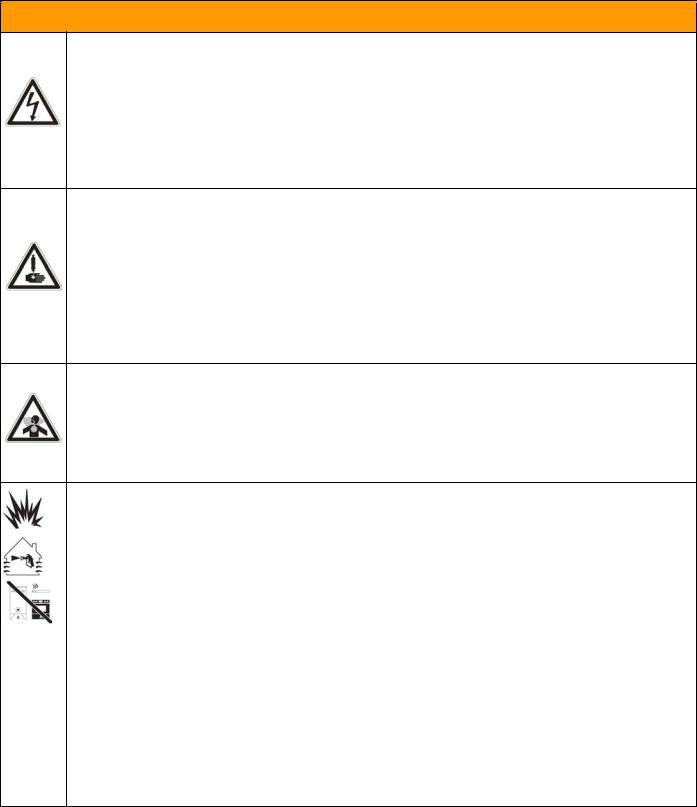
 WARNING
ELECTRIC SHOCK HAZARD
Improper grounding, setup, or usage of the system can cause electric shock.
•Turn off and disconnect power cord before servicing equipment.
•Use only grounded electrical outlets.
•Use only 3-wire extension cords.
•Ensure ground prongs are intact on sprayer and extension cords.
•Do not expose to rain. Store indoors.
SKIN INJECTION HAZARD
High-pressure fluid from dispense valve, hose leaks, or ruptured components will pierce skin. This may look like just a cut, but it is a serious injury that can result in amputation. Get immediate surgical treatment.
•Do not point dispense valve at anyone or at any part of the body.
•Do not put your hand over the end of the dispense nozzle.
•Do not stop or deflect leaks with your hand, body, glove, or rag.
•Follow Pressure Relief Procedure in this manual, when you stop spraying and before cleaning, checking, or servicing equipment.
TOXIC FLUID OR FUMES HAZARD
Toxic fluids or fumes can cause serious injury or death if splashed in the eyes or on skin, inhaled, or swallowed.
•Read MSDS’s to know the specific hazards of the fluids you are using.
•Store hazardous fluid in approved containers, and dispose of it according to applicable guidelines.
•Always wear impervious gloves when spraying or cleaning equipment.
FIRE AND EXPLOSION HAZARD
Flammable fumes, such as solvent and paint fumes, in work area can ignite or explode. To help prevent fire and explosion:
•Use and clean equipment only in well ventilated area.
•Eliminate all ignition sources; such as pilot lights, cigarettes, portable electric lamps, and plastic drop cloths (potential static arc).
•Keep work area free of debris, including solvent, rags and gasoline.
•Do not plug or unplug power cords or turn lights on or off when flammable fumes are present.
•Ground equipment, personnel, object being sprayed, and conductive objects in work area. See Grounding instructions.
•Use only Graco grounded hoses.
•Check gun resistance daily.
•If there is static sparking or you feel a shock, stop operation immediately. Do not use equipment until you identify and correct the problem.
•Do not flush with gun electrostatics on. Do not turn on electrostatics until all solvent is removed from system.
•Keep a working fire extinguisher in the work area.
312393G |
5 of 50 |
Warnings
 WARNING
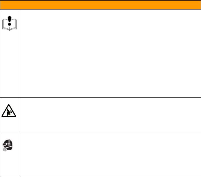
EQUIPMENT MISUSE HAZARD
Misuse can cause death or serious injury.
•Do not operate the unit when fatigued or under the influence of drugs or alcohol.
•Do not exceed the maximum working pressure or temperature rating of the lowest rated system component. See Technical Data in all equipment manuals.
•Use fluids and solvents that are compatible with equipment wetted parts. See Technical Data in all equipment manuals. Read fluid and solvent manufacturer’s warnings. For complete information about your material, request MSDS forms from distributor or retailer.
•Check equipment daily. Repair or replace worn or damaged parts immediately with genuine manufacturer’s replacement parts only.
•Do not alter or modify equipment.
•Use equipment only for its intended purpose. Call your distributor for information.
•Route hoses and cables away from traffic areas, sharp edges, moving parts, and hot surfaces.
•Do not kink or over bend hoses or use hoses to pull equipment.
•Keep children and animals away from work area.
•Comply with all applicable safety regulations.
MOVING PARTS HAZARD
Moving parts can pinch or amputate fingers and other body parts.
•Keep clear of moving parts.
•Do not operate equipment with protective guards or covers removed.
•Pressurized equipment can start without warning. Before checking, moving, or servicing equipment, follow the Pressure Relief Procedure in this manual. Disconnect power or air supply.
PERSONAL PROTECTIVE EQUIPMENT
You must wear appropriate protective equipment when operating, servicing, or when in the operating area of the equipment to help protect you from serious injury, including eye injury, inhalation of toxic fumes, burns, and hearing loss. This equipment includes but is not limited to:
•Protective eyewear
•Clothing and respirator as recommended by the fluid and solvent manufacturer
•Gloves
•Hearing protection
312393G |
6 of 50 |
Installation
Installation
General Information
Accessories are available from Graco. Make certain all accessories are adequately sized and pressure-rated to meet your system needs.
Figures 2 thru 4 are only a guide for identifying system components and for assisting in installation. Contact your Graco distributor or Graco Ohio Customer Service for assistance in designing a system to suit your particular needs.
Unpacking
1.Inspect the shipping container carefully for damage. Contact the carrier promptly if there is damage.
2.Open the box and inspect the contents carefully. There should not be any loose or damaged parts in the container.
3.Compare the packing slip against all the items in the box. Report any shortage or other inspection problems immediately.
4.Remove the PR70 system components from the container. Do not lift the machine by the tanks.
Locate and Install the PR70
1.Locate a bench top or equivalent location to mechanically mount the PR70 dispensing machine.
Verify the location has access to compressed air, AC power and is well ventilated.
2.Place the PR70 onto the designated location. Allow to the machine to rest on the rubber feet provided.
3.Turn the Shield Locking Screws clockwise on both sides to remove the PR70 protective shield.
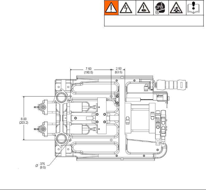
4.Attach the PR70 frame to the selected location by installing fasteners (not provided with unit) thru the 4 mounting holes. Refer to Figure 1 for mounting hole dimensions.
Machine Setup
Avoid contact with electrical inter-connects, when connecting electric power to the machine. Read all manufacturer’s warning and material MSDS to know the specific hazards of the material used.
1.Connect a compressed airline to the input air in the back of the machine.
2.Load material into the on-board or off-board tanks feeding the machine.
3.Using the power cord provided, connect AC power (100-240V, 50/60 Hz, single-phase) to the machine.
Figure 1: Mounting Hole Dimensions for Installing the PR70 Machine (dimensions in inches/mm)
312393G |
7 of 50 |
Component Identification
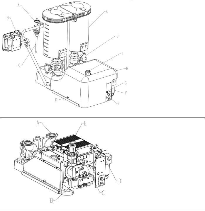
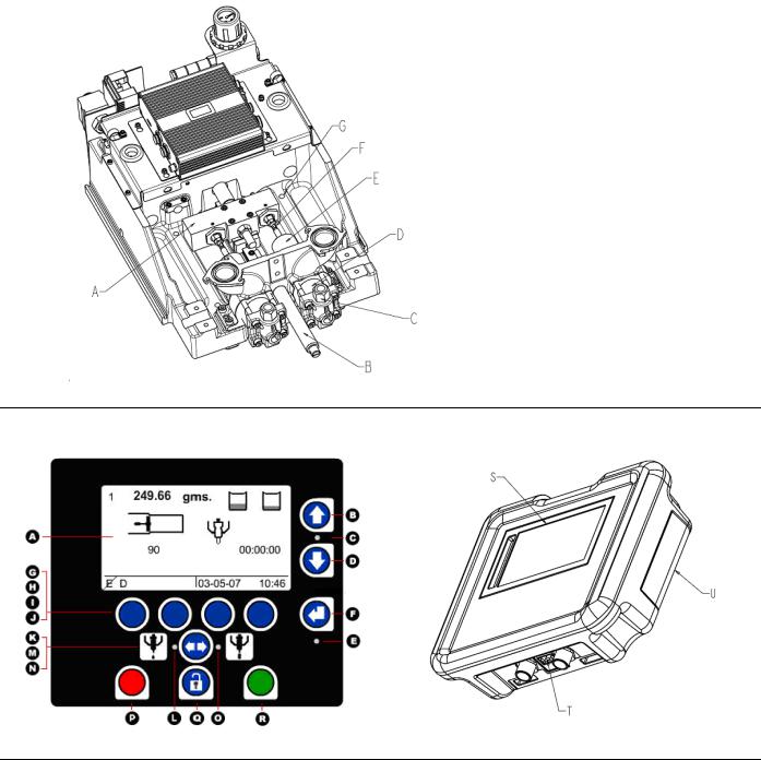
Component Identification
Key:
A Dispense Valve (DV)
B HMI (Human Machine Interface)
C Static Mixer
D Shield Locking Screw
E Power Switch
F Air Filter
G Customer Input Receptacle
H Protective Shield
I Air Pressure Regulator
J Ball Valve (Optional)
K A and B Tanks (Onboard,
Polyethylene versions illustrated).
Figure 2: Typical PR70 (Back View, without Hoses)
Key:
A Pump Assembly
B Solenoid Valves
C Air Cylinder Assembly
D DC Power Supply
E Fluid Control Module (FCM)
Figure 3: PR70 Back View with Shield, Tanks, DV and HMI Removed.
312393G |
8 of 50 |
Component Identification
Key:
A Drive Block
B Hydracheck (optional)
C Check Valve
D Cylinder (Metering Tube)
E Rear Bearing
F Phase Adjustment Screw/Locking
Nut
G Mounting Hole in Base Frame
Figure 4: PR70 Top View with Shield, Tanks, DV and HMI Removed.
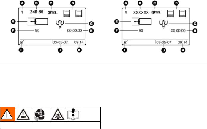
HMI Control and Indicators
Figure 5: PR70 HMI Controls
Key: |
|
|
|
A |
Screen, Display Area |
N |
Operator Mode ICON |
B, D |
Up and Down Keys |
O |
Operator Mode LED |
C |
Up and Down Key LED |
P |
Red Stop or Cancel Key (used to stop machine |
E |
Enter Key LED |
|
operation) |
F |
Enter Key |
Q |
Lock Key (used to enter and exit setup screens) |
G-J |
Soft Keys 1 thru 4 (Left to Right). |
R |
Green Go Key (used to request a shot) |
K |
Shot Mode ICON |
S |
Display area |
L |
Shot Mode LED |
T |
Diagnostic LED’s |
M |
Mode Select Key |
U |
HMI Rear Access Panel (used to access clock |
|
|
|
battery and for reprogramming the HMI). |
312393G |
9 of 50 |
Run Screens
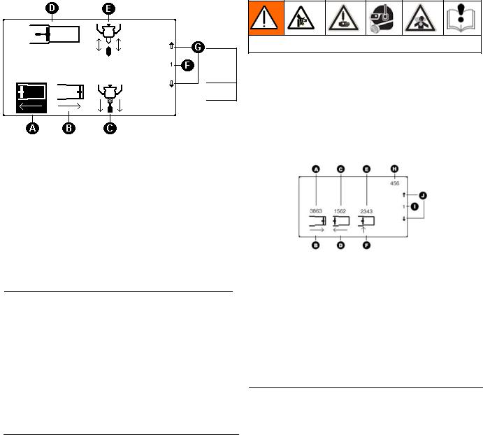
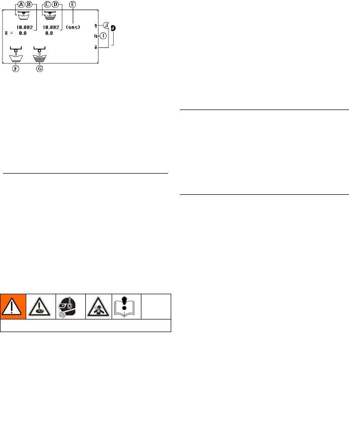
HMI Main Run Screen
Figure 6: Typical PR70 Main Run Screen (Shot and Operator Modes) Respectively)
Key: |
|
|
A Shot Number Field (“x” in Operator Mode) |
F |
Cycle Counter |
B Shot Size Field (“XXXXXX” in Operator Mode) |
G |
DV status Field |
C Shot weight/mass unit of measure (Grams). |
H |
Purge Timer status Field |
D Tank Fill Status Indicators |
I |
Error code status Field |
E Pistons Status Field |
J |
Current Date Field (DD-MM-YY) |
|
K |
Current Time Field (24 Hr. Format) |
Run Screen Operation
Read all manufacturer’s warning and material MSDS to know the specific hazards of the material used.
Machine Mode Selection
To dispense material, one of the following 2 modes must be selected;
•Shot mode dispenses a predetermined amount of material when the machine receives a “Go” command.
•Operator mode dispenses material as long as the machine is receiving a “Go” command.
To select Shot mode:
1.Press  until
until  .
.
2.Press  to accept or
  to cancel. To select Operator mode:
3.Press  until
until  .
.
4.Press  to accept or
  to cancel.
Machine Operation: Shot Mode
1.Place the item or part to be filled below the dispense valve static mixer
2.Press  (green) or the footswitch to start the shot.
3. To cancel the shot, press  .
.
Machine Operation: Operator Mode
1.Place the item or part to be filled below the dispense valve static mixer.
2.Press and hold  (green) or the footswitch to start the shot. The machine will continue to dispense until the
  (green) or the footswitch is released.
The pistons will not retract unless they are almost fully extended. They will automatically retract after 4 minutes. The machine will beep to signal that it is about
to retract. To manually retract the machine, press  .
.
Shot Number Selection
In Shot mode, up to 5 predefined shot sizes may be selected. To select a shot:
1.When the machine is idle (not dispensing a shot) press  or
or  to select the new shot size.
2.Press  to accept, or
  to cancel.
312393G |
10 of 50 |
Disable Mode, Entering Set-up Screens
Machine Disable Mode (“ ”red)
”red)
Figure 6: Typical Run Screen when Machine in “Disable” Mode
1.At any time and from any screen, to immediately disable all machine motion, press  (red).
2.If activated, the purge timer will be disabled
3.To resume operation, the machine must be put back into an operating mode as described in the Machine Mode Selection section.
4.If activated, the purge timer will not restart until a shot is taken.
Setup Screens
Before the machine will operate properly, it must be calibrated and shot size information must be entered.
Entering the Setup Screens
1.From the Run screen press  . If no password has been programmed into the HMI, the Programming Mode Selection Screen (Figure 7) will be displayed.
Figure 7: Programming Mode Selection Screen
2.To enter the calibration screens, press  . To enter the maintenance screens, press
  . Refer to Figure 9 for a screen navigation diagram.
Setup Screens with Passwords Enabled
1.From the Run screen press  . If a password has been programmed, the Password Entry Screen (Figure 8) will be displayed.
Figure 8: Password Entry Screen
2.Enter the 6 digit password by pressing the corresponding soft keys, G-J in Figure 5.
3.After the 6th digit has been entered, press  .
.
4.If the correct password has been entered, the Programming Mode Selection Screen will be displayed. Refer to Figure 9 for a screen navigation diagram.
5.If the incorrect password has been entered, the password entry will need to be repeated until the correct 6-digit sequence is entered.
6.To abort the password entry, press  .
.
312393G |
11 of 50 |

Screen Layout
Figure 9: PR70 Screen Navigation Diagram
312393G |
12 of 50 |
Priming and Calibration
Machine Priming
Before the machine can be properly calibrated with material, it will need to be primed.
Read all manufacturer’s warning and material MSDS to know the specific hazards of the material used.
From the Run Screen press  then press
  . The following screen will be displayed.
Figure 10: Maintenance Screen for Priming (M1)
Key:
AFull Retract ICON
BFull Extend ICON
CChange Dispense Valve Mode  = Always Open
 = Always Closed
 = Opens at Cylinder Entrance (Automatic)
DCurrent Piston Position
ECurrent Dispense Valve Mode
FScreen Number (C1)
G &
&  keys will navigate to adjacent screens.
1.Place a waste container under the dispense valve to capture any dispensed material.
2.Press  until the upper ICON is
  .
.
3.Press  to extend the piston fully.
4.Press  to retract the piston fully.
5.Repeat steps 3 and 4 until both materials dispense from the valve without air.
6.Press  twice to return to the Run screen.
Machine Calibration
Before the machine will accurately dispense, it must be calibrated.
Be careful not to pinch fingers when manually moving the machine drive block.
Piston Position Calibration (C1)
This step should be executed the 1st time the machine is setup, and may not need to be re-executed unless the position sensor, an electronic component or a piston has been replaced.
From the Run Screen press  then press
  . The following screen will be displayed.
Figure 11: Piston Position Calibration Screen (C1)
Key:
AFull Extend position number from last calibration
BFull Extend Command ICON
CFull Retract position number from last calibration
DFull Retract Command ICON
ECylinder Entrance position from last calibration
FCylinder Entrance Command ICON
HCurrent Piston Position Field
IScreen Number (C1)
J &
&  keys will navigate to adjacent screens.
1.Place a waste container under the dispense valve to capture any dispensed material.
2.With air pressure applied to the machine, press  .
.
3.The piston should fully extend and a number between 3600 to 3900 should appear for ‘H’
4.Press  to accept the number or
  to keep the current number.
5.Press  .
.
6.The piston should fully retract and a number between 1250 to 1600 should appear for ‘H’.
7.Press  to accept the number or
  to keep the current number.
8.Decrease the air pressure by adjusting the machine air pressure regulator to a minimal value (i.e. ~ 10 - 20 psi).
9.Press  .
.
312393G |
13 of 50 |
Priming and Calibration
10.The machine pistons should extend slowly until they encounter the cylinder entrance and a number between 2000 to 2400 should appear for ‘H’.
11.If the pistons do not move, manually move the piston by pulling on the machine drive block, until mechanical resistance is encountered at the cylinder entrance.
12.Press  to accept the number or
  to keep the current number.
13.Adjust the Air Pressure Regulator back to a reasonable value for proper machine operation.
14.Press  twice to return to the Run screen.
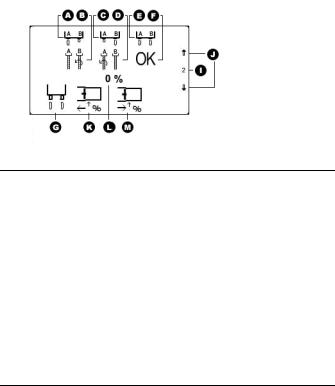
Phasing (C2)
To enable the machine to dispense the correct ratio of material from the A and B tanks and to mix properly, both materials will need to enter the static mixer at the same time. Phasing shots will need to be executed to visually verify that the 2 materials are exiting the dispense valve at the same time.
Remove any static mixer attached to the dispense valve, and replace it with a ratio check nozzle. Place a waste container under the valve to capture any dispensed material.
From the Run screen, press  , then press
  , and then press
  once. The following will screen will be displayed.
Figure 12: Phasing Calibration Screen (C2)
Key:
AA material leads B ICON
BAdjust B side Forward ICON
CB material leads A ICON
DAdjust A side Forward ICON
EA and B Exit the Same Time ICON
FDo NO Mechanical Adjustment ICON
GPhase Shot Request ICON
IScreen Number (C2)
J &
&  keys will navigate to adjacent screens.
KDecrease Phase Shot Percentage Amount ICON
LCurrent Phase Shot Percentage Amount
MIncrease Phase Shot Percentage Amount ICON
1.Select the location where the piston will reverse (from the extend to retract motion) by pressing  or
or  keys. Pressing
  will decrease the phasing shot. Pressing
  will increase the phasing shot. A “+” value indicates that the piston will reverse beyond the cylinder entrance. A “-“ value indicates the piston will reverse prior to reaching the cylinder entrance.
2.Press  (green) or the footswitch.
3.During the shot execution, visually monitor the 2 materials exiting the ratio check nozzle. If the timing of the 2 materials exiting the nozzle cannot be properly observed, press  or
or  accordingly, then repeat step 2.
4.If the A side material exits the ratio nozzle before the B side material (“ ”), turn the B piston Phase Adjustment Screw/ Locking nut and shaft counterclockwise to move the B piston forward, as indicated on the
  ICON. Slight adjustments in the piston shaft will be significant. Adjustments of a quarter turn are typical.
5.If the B side material exits the ratio nozzle before the A side material (“ ”), turn the A piston Phase Adjustment Screw/ Locking nut and shaft counterclockwise to move the A piston forward, as indicated on the
  ICON.
ICON.
6.Repeat step 2 until both materials exit the ratio check nozzle at the same time (“ ”).
”).
7.Press  twice to return to the Run screen.
Open Dispense Valve (ODV) Setting (C3)
The next step in the calibration process is to determine the proper position to open the Dispense Valve (DV) during the shot.
Advancing or increasing the opening position (in millimeters) will build more pressure in the material hoses prior to the dispense valve opening. If the Dispense Valve opens too late in the shot, a surge of material can occur or the piston could stall. If the Dispense Valve opens to early in the shot, material “drooling” at the beginning of the dispense cycle could occur.
From the Run screen, press  , then press
  , and then press
  2 times. The following screen will be displayed.
312393G |
14 of 50 |
Priming and Calibration
From the Run screen, press  , then press
  , then press
  3 times. The following screen will be displayed.
Figure 13: Open Dispense Valve (ODV) Screen (C3)
Key:
ACurrent ODV Adjustment (in mm from the cylinder entrance).
BAdjust ODV value Option ICON.
CRelative ODV Position ICON with respect to cylinder entrance (This ICON will move right or left at +/- mm transition).
DCylinder Entrance ICON (stationary).
IScreen Number (C3)
J &
&  keys will navigate to adjacent screens.
1.To adjust the ODV position with respect to the cylinder entrance, press  .
.
2.Press  to increase the value or
  to decrease the value. Values of – 5.0 mm to + 5.0 mm are allowed.
3.Press  to accept the value or
  to retain the previous value. The default value from the factory is – 1.0 mm.
4.Press  twice to return to the Run screen.
Machine Calibration Shots (C4)
Read all manufacturer’s warning and material MSDS to know the specific hazards of the material used.
Calibration shots are necessary to program the machine to properly dispense the correct amount of
material. Several short CAL shots (“ ”) and several long CAL shots (“
 ”) are required.
Remove the ratio check nozzle, install the static mixer intended to be used, and adjust the air pressure to the level intended for use during normal operation.
The air pressure must be set to operating conditions for this step. Significant changes in air pressure could adversely affect shot accuracy.
Figure 14: Stroke Calibration (CAL) Screen (C4)
Key:
AShort Shot Column ICON
BLast/Current Short Shot weight (mass) entry.
CLong Shot Column ICON
DLast/Current Long Shot weight (mass) entry.
EGrams (Weight or Mass unit used)
FShort Shot ICON
GLong Shot ICON
IScreen Number (C4)
J &
&  keys will navigate to adjacent screens.
1.Press  to arm the machine to take a short CAL shots. The icon will be highlighted (“
 ”). Press
  to de-arm the machine.
2.Place the empty container below the static mixer, and press  (green) or the footswitch.
3.Press  and discard the contents of the material dispensed
4.Repeat the previous 2 steps until the static mixer is filled with material. Verify the material dispensed from the mixer is mixed properly.
5.Place a container on a scale and tare (zero) it.
6.Place the tared container below the static mixer, and press  (green) or the footswitch.
7.Press  to erase existing average weight data.
8.Place the container with the dispensed material on the tared scale.
9.Enter the mass in grams into the HMI, by pressing  or
or  accordingly.
10.Press  to accept the number. The number entered will be transferred to the right of the average icon (“
 ”).
”).
11.Repeat steps 5 through 10, skipping step 7, several times. Each additional shot weight will be averaged in the  row with the previous shots.
312393G |
15 of 50 |
 Loading...