


Instructions - Parts List
This manual contains important |
|
|
|
|
|
|
|
|
|
|
|
|
|
|
|
|
|
|
|
|
|
|
|
|
|
|
|
|
|
|
|
|
|
||
warnings and information. |
)LUVW FKRLFH ZKHQ |
||||||||||||||||
READ AND KEEP FOR REFERENCE. |
|||||||||||||||||
TXDOLW\ FRXQWVΠ|
|||||||||||||||||
INSTRUCTIONS
MANUAL ELECTROSTATIC
PRO™ Xs4 AA
Air-Assisted Spray Gun
100 psi (0.7 MPa, 7 bar) Maximum Air Inlet Pressure
3000 psi (21 MPa, 210 bar) Maximum Working Fluid Pressure Smart Model
See page 3 for a List of Models
U.S. Patent Pending
For use with Class I Group D or Class II 2 G spray materials.
Standard Model
ti1332b
309295
Rev. A
ti1509a
Graco Inc. P.O. Box 1441Minneapolis, MN 55440-1441
COPYRIGHT 2001, Graco Inc. Graco Inc. is registered to I.S. EN ISO 9001
Table of Contents
List of Models . . . . . . . . . . . . . . . . . . . . . . . . . . . . . . . . . . 3
Symbols . . . . . . . . . . . . . . . . . . . . . . . . . . . . . . . . . . . . . . . 3
Warning Symbol. . . . . . . . . . . . . . . . . . . . . . . . . . . . . 3
Caution Symbol . . . . . . . . . . . . . . . . . . . . . . . . . . . . . 3
Warning . . . . . . . . . . . . . . . . . . . . . . . . . . . . . . . . . . . . . . . 4
Introduction . . . . . . . . . . . . . . . . . . . . . . . . . . . . . . . . . . . 7
How the Electrostatic AA Spray Gun Works. . . . . 7
Gun Overview . . . . . . . . . . . . . . . . . . . . . . . . . . . . . . 8
Installation . . . . . . . . . . . . . . . . . . . . . . . . . . . . . . . . . . . . 9
Install the System. . . . . . . . . . . . . . . . . . . . . . . . . . . . 9
Warning Sign . . . . . . . . . . . . . . . . . . . . . . . . . . . . . . . 9
Ventilate the Spray Booth . . . . . . . . . . . . . . . . . . . . . 9
Connect the Air Line . . . . . . . . . . . . . . . . . . . . . . . . .11
Connect the Exhaust Tube . . . . . . . . . . . . . . . . . . . .11
Connect the Fluid Line . . . . . . . . . . . . . . . . . . . . . . 12
Filter the Fluid . . . . . . . . . . . . . . . . . . . . . . . . . . . . . 12
Select a Spray Tip . . . . . . . . . . . . . . . . . . . . . . . . . . . 12
Grounding. . . . . . . . . . . . . . . . . . . . . . . . . . . . . . . . . 13
Check Electrical Grounding . . . . . . . . . . . . . . . . . . 14
Check Fluid Resistivity . . . . . . . . . . . . . . . . . . . . . . 15
Check Fluid Viscosity . . . . . . . . . . . . . . . . . . . . . . . 15
Operation. . . . . . . . . . . . . . . . . . . . . . . . . . . . . . . . . . . . . 16
Low Voltage Adjustment (Smart Guns Only) . . . 16
Maintenance . . . . . . . . . . . . . . . . . . . . . . . . . . . . . . . . . . 17
Flush the Spray Gun . . . . . . . . . . . . . . . . . . . . . . . . 17
Electrical Tests. . . . . . . . . . . . . . . . . . . . . . . . . . . . . . . . . 19
Test Gun Resistance . . . . . . . . . . . . . . . . . . . . . . . . . 19
Test Power Supply Resistance . . . . . . . . . . . . . . . . 20
Test Barrel Resistance . . . . . . . . . . . . . . . . . . . . . . . 21
Troubleshooting . . . . . . . . . . . . . . . . . . . . . . . . . . . . . . . .22
Spray Pattern Troubleshooting . . . . . . . . . . . . . . . .22 Gun Operation Troubleshooting . . . . . . . . . . . . . . .23 Electrical Troubleshooting . . . . . . . . . . . . . . . . . . . .24
Repair . . . . . . . . . . . . . . . . . . . . . . . . . . . . . . . . . . . . . . . . .25
Pressure Relief Procedure . . . . . . . . . . . . . . . . . . . . .25 Prepare the Gun for Service . . . . . . . . . . . . . . . . . . .26
Tools Needed . . . . . . . . . . . . . . . . . . . . . . . . . . . . . . .26
Tip Guard, Air Cap, Spray Tip, or Seat Housing Replacement . . . . . . . . . . . . . . . . . . . . . . . . . . . .27
Electrode Replacement . . . . . . . . . . . . . . . . . . . . . . .29 Fluid Tube Replacement . . . . . . . . . . . . . . . . . . . . . .30 Fluid Filter Removal . . . . . . . . . . . . . . . . . . . . . . . . .30
Fluid Needle Replacement . . . . . . . . . . . . . . . . . . . .31
Barrel Removal. . . . . . . . . . . . . . . . . . . . . . . . . . . . . .32 Barrel Installation. . . . . . . . . . . . . . . . . . . . . . . . . . . .32
Power Supply Removal and Replacement. . . . . . .33 Turbine Alternator Removal and Replacement. . .34 Atomizing Air Adjustment Valve Repair. . . . . . . .35
Air Valve Repair. . . . . . . . . . . . . . . . . . . . . . . . . . . . .36 ES ON/OFF Valve Repair. . . . . . . . . . . . . . . . . . . . .37
Parts . . . . . . . . . . . . . . . . . . . . . . . . . . . . . . . . . . . . . . . . . .38 Accessories . . . . . . . . . . . . . . . . . . . . . . . . . . . . . . . . . . . .46 Air Line Accessories . . . . . . . . . . . . . . . . . . . . . . . . .46 Fluid Line Accessories . . . . . . . . . . . . . . . . . . . . . . .46 Gun Accessories . . . . . . . . . . . . . . . . . . . . . . . . . . . . .47
Miscellaneous Accessories . . . . . . . . . . . . . . . . . . . .47
Spray Tip Selection Chart. . . . . . . . . . . . . . . . . . . . . . . .48 Technical Data. . . . . . . . . . . . . . . . . . . . . . . . . . . . . . . . . .49
2 |
309295 |

List of Models
List of Models
Part No. |
Model |
Description |
Operation |
|
Manual |
||||
|
|
|
||
|
|
|
|
|
244572 |
PRO Xs4 AA |
Manual Air-Assisted Spray Gun |
309296/ |
|
|
|
|
3W9296/3Z9296 |
|
|
|
|
|
|
244573 |
PRO Xs4 AA |
Manual Air-Assisted Spray Gun with smart display |
309296/ |
|
|
|
|
3W9296/3Z9296 |
|
|
|
|
|
Symbols
Warning Symbol
 WARNING
This symbol alerts you to the possibility of serious injury or death if you do not follow the instructions.
Caution Symbol
CAUTION
This symbol alerts you to the possibility of damage to or destruction of equipment if you do not follow the instructions.
309295 |
3 |

Warning
 WARNING
Fire, Explosion, and Electric Shock Hazard
Improper grounding, poor air ventilation, open flames, or sparks can cause a hazardous condition and result in a fire, explosion, or electric shock.
•Electrostatic equipment must be used only by trained, qualified personnel who understand the requirements in this manual.
•Ground the equipment, all personnel in or close to the spray area, the object being sprayed, and all conductive objects in the spray area. See “Grounding”, page 13.
•Check gun resistance daily. See “Test Gun Resistance” on page 19.
•If there is any static sparking while using the equipment, stop spraying immediately. Identify and correct the problem.
•Provide fresh air ventilation to avoid buildup of flammable or toxic vapors. Interlock the gun air supply to prevent operation unless ventilating fans are on. See “Ventilate the Spray Booth” on page 9.
•Use solvents that comply with local regulations. Flash point should be higher than 100°F (38°C).
•Do not flush with the gun electrostatics on. Do not turn on the gun electrostatics until all solvent is removed from the system.
•Keep the spray area free of debris and rags. Do not store solvent and flammable fluids in the spray area.
•Eliminate all ignition sources such as pilot lights, cigarettes, and static arcs from plastic drop cloths. Do not plug in or unplug power cords or turn lights on or off in the spray area.
•Use only non-sparking tools to clean residue from the booth and hangers.
4 |
309295 |

Warning
WARNING
Fluid Injection Hazard
Spray from the gun, hose leaks, or ruptured components can inject fluid into your body and cause an extremely serious injury, including the need for amputation. Splashing fluid in the eyes or on the skin can also cause serious injury.
•Fluid injected into the skin might look like just a cut, but is a serious injury. Get immediate medical attention.
•Do not point the gun at anyone or at any part of the body. Do not put your hand or fingers over the spray tip. Do not stop or deflect fluid leaks with your hand, body, glove, or rag.
•Never spray without the tip guard in place.
•Lock the trigger safety when you stop spraying.
•Follow the “Pressure Relief Procedure”, page 25, when you stop spraying and before cleaning, checking, or repairing equipment.
•Check the hoses and couplings daily. Replace worn, damaged, or loose parts immediately. Permanently coupled hoses cannot be repaired; replace the entire hose.
•Tighten all fluid connections before each use.
Toxic Fluid Hazard
Hazardous fluids or toxic fumes can cause a serious injury or death if splashed in the eyes or on the skin, swallowed, or inhaled.
•Know the specific hazards of the fluid you are using. Read the fluid manufacturer’s warnings.
•Store hazardous fluid in an approved container. Dispose of the hazardous fluid according to all local, state, and national guidelines.
•Wear appropriate protective clothing, gloves, eyewear, and respirator.
309295 |
5 |

Warning
 WARNING
Equipment Misuse Hazard
Equipment misuse can cause the equipment to rupture, malfunction, or start unexpectedly and result in a serious injury.
•This equipment is for professional use only.
•Read all manuals, tags, and labels before operating the equipment.
•Use the equipment only for its intended purpose. If you are uncertain, call your Graco distributor.
•Do not alter or modify equipment. Use only genuine Graco parts and accessories.
•Check the equipment daily. Repair or replace worn or damaged parts immediately.
•Do not exceed the maximum working pressure of the lowest rated system component. Maximum working fluid pressure of this equipment is 3000 psi (21 MPa, 210 bar).
•Use fluids and solvents that are compatible with the equipment wetted parts. See the Technical Data section of all equipment manuals. Read the fluid and solvent manufacturer’s warnings.
•Route the hoses away from traffic areas, sharp edges, moving parts, and hot surfaces. Do not expose Graco hoses to temperatures above 180°F (82°C) or below -40°F (-40°C).
•Wear hearing protection when operating this equipment.
•Comply with all applicable local, state, and national fire, electrical, and other safety regulations.
6 |
309295 |

Introduction
Introduction
How the Electrostatic AA
Spray Gun Works
 WARNING
Fluid Injection Hazard
Remember, this is not an air spray gun.
For your safety, read and follow all Warnings in this manual.
The air-assisted spray gun combines airless and air spraying concepts. The spray tip shapes the fluid into a fan pattern, as does a conventional airless spray tip. Air from the air cap further atomizes the fluid and completes the atomization of the fluid tails to produce a uniform pattern.
As the gun is triggered, part of the regulated air operates the turbine and the rest of the air atomizes the fluid being sprayed. The turbine generates power, which is converted by the power cartridge to supply high voltage current to the gun’s electrode.
The regulated air that is directed to the air cap can be further controlled using the gun’s atomizing air adjustment valve. This valve can be used to restrict air flow to the air cap while maintaining sufficient air flow to the turbine.The atomizing air adjustment valve does not control pattern width. To change pattern width, a new tip size must be used.
The high working fluid pressure of this gun provides the power needed to atomize higher solids materials.
The gun’s internal power supply provides high voltage current. The fluid is electrostatically charged as it passes the electrode. The charged fluid is attracted to the grounded workpiece, wrapping around and evenly coating all surfaces.
NOTE: For airless atomization, if desired, turn the gun’s atomizing air adjustment valve completely off. Closing this valve does not affect turbine operation.
309295 |
7 |
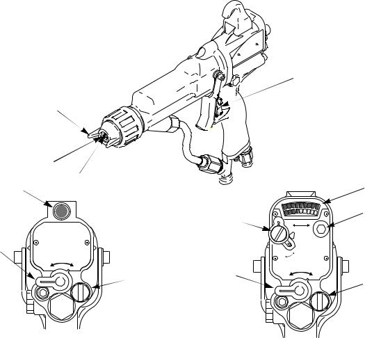
Gun Overview
The electrostatic gun includes the following controls (see Fig. 1).
•Air cap/tip guard and spray tip. Never spray without the tip guard. See page 48 for spray tip sizes.
•Trigger safety lock. Prevents the gun from spraying.
•Atomizing AIR adjustment valve. Adjusts atomizing air.
TIP GUARD
AIR CAP
SPRAY TIP
ES INDICATOR
ES ON/OFF |
|
|
(I = ON, |
|
|
0 = OFF) |
I ES |
O |
|
|
AIR
ti1366a
Standard Gun
Fig. 1. Gun Overview
Introduction
•ES ON/OFF valve. Turns electrostatics ON (I) or OFF (0).
•ES INDICATOR (standard gun only). Green when ES is ON (I).
•Voltage/current DISPLAY (smart models only).
Shows voltage (V) and current (A). Green=spray, yellow/red=see Troubleshooting, page 24.
•ES HI/LO switch (smart models only). Sets voltage to HI or LO (factory settings).
•LO voltage adjustment (smart models only).
Remove plug to adjust to four settings.
TRIGGER SAFETY LOCK
ti1509a
|
|
|
DISPLAY |
ES HI/LO |
|
|
LO |
0 |
KV |
100% |
|
|
|
µα |
|
|
|
HI |
|
LO |
ES |
|
|
ES ON/OFF |
I |
ES |
O |
(I = ON, |
|
|
AIR |
0 = OFF) |
|
|
|
ti1333a
Smart Gun
8 |
309295 |

Installation
Installation
Install the System
 WARNING
Fire, Explosion, and Electric Shock
Hazard
Installing and servicing this equipment requires access to parts which may cause electric shock or other serious injury if work is not performed properly.
• Do not install or service this equipment unless you are trained and qualified.
•Be sure your installation complies with National, State and Local codes for the installation of electrical apparatus in a Class I, Group D or a Class II 2G Hazardous Location.
•Comply with all applicable local, state, and national fire, electrical, and other safety regulations.
Fig. 2 shows a typical electrostatic air-assisted spray system. It is not an actual system design. For assistance in designing a system to suit your particular needs, contact your Graco distributor.
Warning Sign
Mount warning signs in the spray area where they can easily be seen and read by all operators. An English Warning Sign is provided with the gun.
Ventilate the Spray Booth
 WARNING
Flammable or Toxic Vapor Hazard
Provide fresh air ventilation to avoid the buildup of flammable or toxic vapors. Do not operate the gun unless ventilation fans are operating.
Electrically interlock the gun air supply with the ventilators to prevent gun operation without ventilating fans operating. Check and follow all National, State, and Local codes regarding air exhaust velocity requirements.
NOTE: High velocity air exhaust will decrease the operating efficiency of the electrostatic system. Air exhaust velocity of 100 ft/min (31 linear meters/minute) should be sufficient.
309295 |
9 |

Installation
D |
C* |
A |
B* D |
C |
The air supply to the gun must be electrically interlocked with the ventilators to prevent the power supply from operating without ventilating fans on.
P
H  J*
J*
L
M
T
*R
G *E
F X
K
O
S
Q* 
V
W
 N
N
U*
Non-Hazardous Area
Fig. 2. Typical Installation
Key |
|
A |
Main Air Supply Line |
B* |
Ventilation Fan Interlock Solenoid Valve |
C* |
Main Air Supply Shutoff Valve (bleed-type) |
D |
Air Line Filter/Water Separator |
E* |
Pump Air Supply Shutoff Valve (bleed-type) |
FAir Line Lubricator
GAir Pressure Regulator
HPump
J* Pump Ground Wire
KFluid Filter
LFluid Supply Line Shutoff Valve
MFluid Pressure Regulator
NGrounded Fluid Supply Line, with spring guards
ti1514b
Hazardous Area
OGun Air Regulator
PGun Air Supply Line Shutoff Valve
Q* |
Air Hose Ground Wire |
R* |
Graco Grounded Air Hose |
SElectrostatic Air-Assisted Spray Gun
TFluid Pressure Gauge
U* Fluid Drain Valve
VGun Air Inlet
WGun Fluid Inlet
XPump Runaway Valve
*Required for safe operation. Must be purchased separately. NOTE: Solenoid valve (B) is not offered as a Graco accessory.
10 |
309295 |
Connect the Air Line
 WARNING
Electric Shock Hazard
To reduce the risk of electric shock or other serious injury, the air supply hose must be electrically connected to a true earth ground. Use only Graco Grounded Air
Supply Hose.
1.Connect the Graco Grounded Air Supply Hose (R) between the air supply line and the gun's air inlet
(V). The gun air inlet fitting has a left-hand thread. Connect the air supply hose ground wire (Q) to a true earth ground.
2.Install an air line filter/water separator (D) on the air line to ensure a dry, clean air supply to the gun. Dirt and moisture can ruin the appearance of your finished workpiece and can cause the gun to malfunction.
Installation
3.Install a bleed-type air regulator (G, O) on the pump and gun air supply lines to control air pressure to the pump and gun.
 WARNING
Fluid Injection Hazard
The bleed-type air valve (E) is required in your system to relieve air trapped between
the valve and the pump after the air regulator is shut off. Trapped air can cause the
pump to cycle unexpectedly, which can result in serious injury, including fluid injection and splashing fluid in the eyes or on the skin.
4.Install a bleed-type air valve (E) on the pump air line to shut off air to the pump. Install an additional bleed-type air valve (C) on the main air line (A) to isolate the accessories for servicing.
5.Install an air shutoff valve ( P) on each gun air supply line to shut off air to the gun(s).
 WARNING
Fluid Injection Hazard
To reduce the risk of serious injury due to component rupture, including fluid injection, pump pressure must be limited by the pump air regulator. Do not rely on the gun fluid regulator to limit the fluid pressure to the gun.
The fluid supply pump must be prevented from producing a fluid pressure greater than the 3000 psi (21 MPa, 210 bar) Maximum Working Fluid Pressure of the gun. For example, the air supply pressure to a 30:1 ratio pump must not exceed 100 psi (0.7 MPa, 7 bar).
Connect the Exhaust Tube
Press the exhaust tube (38) onto the barbed adapter on the bottom of the gun handle. Secure the tube with the clamp (39).
309295 |
11 |

Installation
Connect the Fluid Line |
Filter the Fluid |
1.Before connecting the fluid line (N), blow it out with air and flush it with solvent. Use solvent which is compatible with the fluid to be sprayed.
2.Install a fluid regulator (M) on the fluid line to control fluid pressure to the gun.
 WARNING
Fluid Injection Hazard
The fluid drain valve (U) is required in your system to assist in relieving fluid pressure
in the displacement pump, hose and gun. Triggering the gun to relieve pressure may
not be sufficient. Install a drain valve close to the pump's fluid outlet. The drain valve reduces the risk of serious injury, including fluid injection and splashing in the eyes or on the skin.
3.Install a drain valve (U) near the pump outlet.
4.Connect the fluid line to the 1/4 npsm gun fluid inlet (W).
5.Before running any paint through the spray gun, flush it out with a compatible solvent.
Install a fluid filter (K) at the pump outlet to remove particles and sediment which could clog the spray tip.
The gun includes an inline fluid filter (1) for additional filtration.
Select a Spray Tip
 WARNING
Fluid Injection Hazard
To reduce the risk of a fluid injection injury, always follow the “Pressure Relief Procedure”, page 25, before removing or installing the spray tip, air cap, or tip guard.
The fluid output and pattern width depend on the size of the spray tip, the fluid viscosity, and the fluid pressure. Use the “Spray Tip Selection Chart”, page 48, as a guide for selecting the appropriate spray tip for your application.
Refer to the gun operation manual to install the spray tip.
12 |
309295 |

Grounding
 WARNING
Fire, Explosion, and Electric Shock
Hazard
When operating the electrostatic gun, any ungrounded objects in the spray area (people, containers, tools, etc.) can become electrically charged. Improper grounding can result in static sparking, which can cause a fire, explosion, or electric shock. Follow the grounding instructions below.
The following are minimum grounding requirements for a basic electrostatic system. Your system may include other equipment or objects which must be grounded. Check your local electrical code for detailed grounding instructions. Your system must be connected to a true earth ground.
•Pump: ground the pump by connecting a ground wire and clamp as described in your separate pump instruction manual.
•Electrostatic Air-Assisted Spray Gun: ground the gun by connecting the Graco Grounded Air Hose and connecting the air hose ground wire to a true earth ground. See “Check Electrical Grounding”, page 14.
ti1259a
•Air compressors: ground the equipment according to the manufacturer's recommendations.
•All air and fluid lines must be properly grounded. Use only grounded hoses with a maximum of 100 feet (30.5 m) combined hose length to ensure grounding continuity.
Installation
•All persons entering the spray area: shoes must have conductive soles, such as leather, or personal grounding straps must be worn. Do not wear shoes with non-conductive soles such as rubber or plastic. If gloves are worn, cut off fingers or cut out palm area, to ensure your hand contacts the grounded gun handle.
•Object being sprayed: keep the workpiece hangers clean and grounded at all times. Resistance must not exceed 1 megohm.
•The floor of the spray area: must be electrically conductive and grounded. Do not cover the floor with cardboard or any non-conductive material which would interrupt grounding continuity.
•Flammable liquids in the spray area: must be kept in approved, grounded containers. Do not use plastic containers. Do not store more than the quantity needed for one shift.
•All electrically conductive objects or devices in the spray area: including fluid containers and wash cans, must be properly grounded.
309295 |
13 |

Check Electrical Grounding
 WARNING
Fire, Explosion, and Electric Shock
Hazard
Megohmmeter Part No. 241079 (AA-see Fig. 3) is not approved for use in a hazardous area. To reduce the risk of sparking, do not use the megohmmeter to check electrical grounding unless:
• The gun has been removed from the hazardous area;
•Or all spraying devices in the hazardous area are turned off, ventilation fans in the hazardous area are operating, and there are no flammable vapors in the area (such as open solvent containers or fumes from spraying).
Failure to follow this warning could cause fire, explosion, and electric shock and result in serious injury and property damage.
1.Have a qualified electrician check the electrical grounding continuity of the spray gun and air hose.
2.Turn the ES ON/OFF valve OFF.
I |
ES |
O |
ti1337a
Installation
3.Turn off the air and fluid supply to the gun. The fluid hose must not have any fluid in it.
4.Make sure the grounded air hose (R) is connected and the hose ground wire is connected to a true earth ground.
ti1259a
5.Measure the resistance between the gun handle (BB) and a true earth ground (CC). Use an applied voltage of 500 minimum to 1000 volts maximum. The resistance should not exceed 1 megohm. See Fig. 3.
6.If the resistance is greater than 1 megohm, check the tightness of the ground connections and be sure the air hose ground wire is connected to a true earth ground. If the resistance is still too high, replace the air hose.
BB
AA
CC
ti1340a
Fig. 3. Check Gun Grounding
Fig. 1.
14 |
309295 |

Check Fluid Resistivity
 WARNING
Fire, Explosion, and Electric Shock
Hazard
Check the fluid resistivity in a non-hazard- ous area only. Resistance Meter 722886 and Probe 722860 are not approved for use in a hazardous area.
Failure to follow this warning could cause fire, explosion, electric shock and result in serious injury and property damage.
Graco Part No. 722886 Resistance Meter and 722860 Probe are available as accessories to check that the resistivity of the fluid being sprayed meets the requirements of an electrostatic air-assisted spray system.
Follow the instructions included with the meter and probe. Readings of 25 megohms-cm and above provide the best electrostatic results.
Installation
Check Fluid Viscosity
To check fluid viscosity you will need:
•a viscosity cup
•a stopwatch.
1.Completely submerge the viscosity cup in the fluid. Lift the cup out quickly, starting the stopwatch as soon as the cup is completely removed.
2.Watch the stream of fluid coming from the bottom of the cup. As soon as there is a break in the stream, shut off the stopwatch.
3.Record the fluid type, elapsed time, and size of the viscosity cup.
4.If the viscosity is too high or too low, contact the material supplier and adjust as necessary.
309295 |
15 |
 Loading...