


 Loading...
Graco P06DCK, P06ECK, P06LCK, P06MCK, P06DSG Instruction manual
...
Instructions - Parts List
Two-Ball NXT® |
|
1000cc Pumps |
EN |
|
311833G |
|
|
Designed for low pressure, medium volume circulation of finishing materials.
For professional use only.
Models P06DCK, P06ECK, P06LCK, P06MCK,
P06DSG*, P06ESG*, P06LSG*, P06MSG*
620 psi (4.2 MPa, 42.7 bar) Maximum Working Pressure 100 psi (0.69 MPa, 6.9 bar) Maximum Air Inlet Pressure
* Uses plate check valves instead of ball check valves.
Models P10DCK, P10ECK, P10LCK, P10MCK, P10LCS
1180 psi (8.14 MPa, 81.4 bar) Maximum Working Pressure 100 psi (0.69 MPa, 6.9 bar) Maximum Air Inlet Pressure
Important Safety Instructions
Read all warnings and instructions in Operation manual.
Save these instructions.
See page 2 for Table of Contents.
Patent Pending
ti8377b
II 2 G
Contents
Pumps with NXT® Air Motors Part No. Matrix . . . . 3 Warnings . . . . . . . . . . . . . . . . . . . . . . . . . . . . . . . . . 4 Installation . . . . . . . . . . . . . . . . . . . . . . . . . . . . . . . . 6
Grounding . . . . . . . . . . . . . . . . . . . . . . . . . . . . . . 6 Accessories . . . . . . . . . . . . . . . . . . . . . . . . . . . . . 6 Flush Before Using Equipment . . . . . . . . . . . . . . 7
Operation . . . . . . . . . . . . . . . . . . . . . . . . . . . . . . . . . 8
Pressure Relief Procedure . . . . . . . . . . . . . . . . . 8
Maintenance . . . . . . . . . . . . . . . . . . . . . . . . . . . . . . . 9
Shutdown . . . . . . . . . . . . . . . . . . . . . . . . . . . . . . 9 Care of the Pump . . . . . . . . . . . . . . . . . . . . . . . . 9 Flushing . . . . . . . . . . . . . . . . . . . . . . . . . . . . . . . 9 Lubrication . . . . . . . . . . . . . . . . . . . . . . . . . . . . . 9
Troubleshooting . . . . . . . . . . . . . . . . . . . . . . . . . . 11
Repair . . . . . . . . . . . . . . . . . . . . . . . . . . . . . . . . . . . 12
Required Tools . . . . . . . . . . . . . . . . . . . . . . . . . 12
Disconnect the Lower . . . . . . . . . . . . . . . . . . . . 12
Reconnect the Lower . . . . . . . . . . . . . . . . . . . . . 13
Models . . . . . . . . . . . . . . . . . . . . . . . . . . . . . . . . . .
P06DCK, P06ECK, P06LCK, P06MCK, . . . . .
P10DCK, P10ECK, P10LCK, P10MCK,
P10LCS . . . . . . . . . . . . . . . . . . . . . . . . . . . . 14
Parts List . . . . . . . . . . . . . . . . . . . . . . . . . . . . . . . . . 15
Dimensions . . . . . . . . . . . . . . . . . . . . . . . . . . . . . . . 16
Pump Mounting Hole Diagram . . . . . . . . . . . . . . . 17
Technical Data . . . . . . . . . . . . . . . . . . . . . . . . . . . . 18
Graco Standard Warranty . . . . . . . . . . . . . . . . . . . 20
Graco Information . . . . . . . . . . . . . . . . . . . . . . . . . 20
2 |
311833G |

Pumps with NXT® Air Motors Part No. Matrix
Pumps with NXT® Air Motors Part No. Matrix
Check your pump’s identification plate (ID) for the 6-digit part number of your pump. Use the following matrix to define the construction of your pump, based on the six digits. For example, Pump Part No. P 0 6 M S G represents the
pump (P), pressure ratio (0 6 :1), low noise exhaust motor with DataTrak™ (M), stainless steel construction (S) PTFE/PTFE packing configuration (G). To order replacement parts, see Parts List section starting on page 15. The digits in the matrix do not correspond to the Ref. Nos. in the Parts drawings and lists.
P |
0 6 |
|
|
M |
|
S |
|
G |
|
|
|
|
|
|
|
|
|
|
|
First |
Second and Third |
|
|
|
|
|
|
|
|
Digit |
|
Fourth Digit |
|
Fifth Digit |
|
Sixth Digit |
|||
Digit |
|
|
|
||||||
|
|
|
|
|
|
|
|
|
|
|
Pressure Ratio (xx:1) |
|
Exhaust |
|
Communication |
|
Material |
|
Packings |
|
|
|
|
|
|
|
|
|
|
P |
06 |
D |
De-icing |
|
none |
C |
Carbon Steel |
G |
PTFE / PTFE |
(pumps) |
|
|
|
|
|
|
|
|
|
10 |
E |
De-icing |
|
DataTrak |
S |
Stainless |
K |
UHMW / Leather |
|
|
|
||||||||
|
|
|
|
|
|
|
Steel |
|
|
|
|
|
|
|
|
|
|
|
|
|
|
L |
Low Noise |
|
none |
|
|
S |
Severe Duty |
|
|
|
|
|
|
|
|
|
(PTFE/UHMWP) |
|
|
|
|
|
|
|
|
|
|
|
|
M |
Low Noise |
|
DataTrak |
|
|
|
|
|
|
|
|
|
|
|
|
|
|
|
|
|
|
|
|
|
|
|
|
|
|
|
|
|
|
|
|
|
|
|
|
|
|
|
|
|
|
|
|
|
|
|
|
|
|
|
|
|
|
|
|
|
|
|
|
|
|
|
|
311833G |
3 |
Warnings
Warnings
The following warnings are for the setup, use, grounding, maintenance, and repair of this equipment. The exclamation point symbol alerts you to a general warning and the hazard symbol refers to procedure-specific risk. Refer back to these warnings. Additional, product-specific warnings may be found throughout the body of this manual where applicable.
 WARNING
EQUIPMENT MISUSE HAZARD
Misuse can cause death or serious injury.
•Do not operate the unit when fatigued or under the influence of drugs or alcohol.
•Do not exceed the maximum working pressure or temperature rating of the lowest rated system component. See Technical Data in all equipment manuals.
•Use fluids and solvents that are compatible with equipment wetted parts. See Technical Data in all equipment manuals. Read fluid and solvent manufacturer’s warnings. For complete information about your material, request MSDS forms from distributor or retailer.
•Check equipment daily. Repair or replace worn or damaged parts immediately with genuine manufacturer’s replacement parts only.
•Do not alter or modify equipment.
•Use equipment only for its intended purpose. Call your distributor for information.
•Route hoses and cables away from traffic areas, sharp edges, moving parts, and hot surfaces.
•Do not kink or over bend hoses or use hoses to pull equipment.
•Keep children and animals away from work area.
•Comply with all applicable safety regulations.
TOXIC FLUID OR FUMES HAZARD
Toxic fluids or fumes can cause serious injury or death if splashed in the eyes or on skin, inhaled, or swallowed.
•Read MSDS’s to know the specific hazards of the fluids you are using.
•Store hazardous fluid in approved containers, and dispose of it according to applicable guidelines.
•Always wear impervious gloves when spraying or cleaning equipment.
FIRE AND EXPLOSION HAZARD
Flammable fumes, such as solvent and paint fumes, in work area can ignite or explode. To help prevent fire and explosion:
• Use equipment only in well ventilated area.
• Eliminate all ignition sources; such as pilot lights, cigarettes, portable electric lamps, and plastic drop cloths (potential static arc).
• Keep work area free of debris, including solvent, rags and gasoline.
•Do not plug or unplug power cords, or turn power or light switches on or off when flammable fumes are present.
•Ground all equipment in the work area. See Grounding instructions.
•Use only grounded hoses.
•Hold gun firmly to side of grounded pail when triggering into pail.
•If there is static sparking or you feel a shock, stop operation immediately. Do not use equipment until you identify and correct the problem.
•Keep a working fire extinguisher in the work area.
4 |
311833G |
Warnings
 WARNING
PRESSURIZED EQUIPMENT HAZARD
Fluid from the gun/dispense valve, leaks, or ruptured components can splash in the eyes or on skin and cause serious injury.
•Follow Pressure Relief Procedure in this manual, when you stop spraying and before cleaning, checking, or servicing equipment.
•Tighten all fluid connections before operating the equipment.
•Check hoses, tubes, and couplings daily. Replace worn or damaged parts immediately.
MOVING PARTS HAZARD
Moving parts can pinch or amputate fingers and other body parts.
•Keep clear of moving parts.
•Do not operate equipment with protective guards or covers removed.
•Pressurized equipment can start without warning. Before checking, moving, or servicing equipment, follow the Pressure Relief Procedure in this manual. Disconnect power or air supply.
SKIN INJECTION HAZARD
High-pressure fluid from dispense valve, hose leaks, or ruptured components will pierce skin. This may look like just a cut, but it is a serious injury that can result in amputation. Get immediate surgical treatment.
•Do not point dispense valve at anyone or at any part of the body.
•Do not put your hand over the end of the dispense nozzle.
•Do not stop or deflect leaks with your hand, body, glove, or rag.
•Follow Pressure Relief Procedure in this manual, when you stop spraying and before cleaning, checking, or servicing equipment.
311833G |
5 |
Installation
Installation
Grounding
The equipment must be grounded. Grounding reduces the risk of static and electric shock by providing an escape wire for the electrical current due to static build up or in the event of a short circuit.
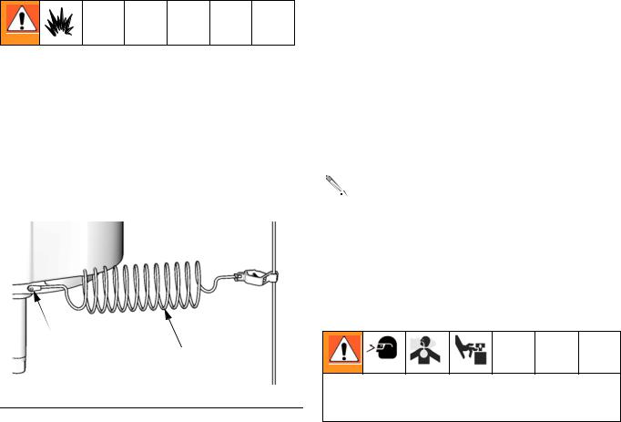
Pump: Use the ground screw (X) and lockwasher on the motor to attach ground wire 244524 (Y). Tighten the screw securely. Connect the other end of the ground wire to a true earth ground.
 X
X
 Y
Y
TI8250a
FIG. 1
Air and fluid hoses: use only electrically conductive hoses. with a maximum of 500 ft. (150 m) combined hose length to ensure grounding continuity. Check electrical resistance of hoses. If total resistance to ground exceeds 29 megohms, replace hose immediately.
Air compressor: follow manufacturer’s recommendations.
Spray gun: ground through connection to a properly grounded fluid hose and pump.
Fluid supply container: follow local code.
Object being sprayed: follow local code.
Solvent pails used when flushing: follow local code. Use only conductive metal pails, placed on a grounded surface. Do not place the pail on a nonconductive surface, such as paper or cardboard, which interrupts grounding continuity.
To maintain grounding continuity when flushing or relieving pressure: hold metal part of the spray gun firmly to the side of a grounded metal pail, then trigger the gun.
Accessories
Accessory Air Control Kits are available for the NXT 
 Air Motor. The kits include a master air valve, air
regulator, and filter. Order the kit separately. See manual 311239 for more information.
Air Line
•Bleed-type master air valve: required in your system to relieve air trapped between it and the air motor when the valve is closed.
Trapped air can cause the pump to cycle unexpectedly, which could result in serious injury from splashing or moving parts.
Be sure the valve is easily accessible from the pump and located downstream from the air regulator.
•Pump air regulator: to control pump speed and outlet pressure. Locate it close to the pump.
•Air line filter: removes harmful dirt and moisture from compressed air supply.
•Second bleed-type air valve: isolates air line accessories for servicing. Locate upstream from all other air line accessories.
•Gun air regulator: controls air pressure to the gun.
Fluid Line
•Fluid filter: with a 60 mesh (250 micron) stainless steel element to filter particles from the fluid as it leaves the pump.
6 |
311833G |
Loading...