


 Loading...
Operation, Parts |
|
RTX1400, RTX2000 & RTX2500 |
3A3258J |
Interior Texture Sprayers |
|
|
EN |
For water-based materials only. For professional use only.
Models: RTX1400si, RTX2000pi & RTX2500pi
70 psi (4.8 bar, 0.48 MPa) Maximum Working Pressure
100 psi (6.9 bar, 0.69 MPa) Maximum Working Pressure (RTX2500pi)
Important Safety Instructions
Read all warnings and instructions in this manual and related manuals. Be familiar with the controls and the proper usage of the equipment. Save these instructions.
Related Manuals
RTX1400si 120V Gun – 311777 RTX1400si 230V, RTX2000pi & RTX2500pi Gun – 3A3373
ti27336a
??  ??
?? 


www.graco.com/techsupport 
Use only genuine Graco replacement parts.
The use of non-Graco replacement parts may void warranty.

Contents
Contents
Models . . . . . . . . . . . . . . . . . . . . . . . . . . . . . . . . . . . . . . . . . . . . . . . . . . . . . . . . . . . . . . . 3 Warnings . . . . . . . . . . . . . . . . . . . . . . . . . . . . . . . . . . . . . . . . . . . . . . . . . . . . . . . . . . . . . 4 Component Identification . . . . . . . . . . . . . . . . . . . . . . . . . . . . . . . . . . . . . . . . . . . . . . . . 7
RTX1400si . . . . . . . . . . . . . . . . . . . . . . . . . . . . . . . . . . . . . . . . . . . . . . . . . . . . . . . . . 7 RTX2000pi & RTX2500pi . . . . . . . . . . . . . . . . . . . . . . . . . . . . . . . . . . . . . . . . . . . . . 8
Preparation . . . . . . . . . . . . . . . . . . . . . . . . . . . . . . . . . . . . . . . . . . . . . . . . . . . . . . . . . . . 9
Pressure Relief Procedure . . . . . . . . . . . . . . . . . . . . . . . . . . . . . . . . . . . . . . . . . . . . . 9 Grounding . . . . . . . . . . . . . . . . . . . . . . . . . . . . . . . . . . . . . . . . . . . . . . . . . . . . . . . . . 9 Power Requirements . . . . . . . . . . . . . . . . . . . . . . . . . . . . . . . . . . . . . . . . . . . . . . . . . 9 Extension Cords . . . . . . . . . . . . . . . . . . . . . . . . . . . . . . . . . . . . . . . . . . . . . . . . . . . . 9 Auxiliary Air Compressor . . . . . . . . . . . . . . . . . . . . . . . . . . . . . . . . . . . . . . . . . . . . . 10 Generator Requirements . . . . . . . . . . . . . . . . . . . . . . . . . . . . . . . . . . . . . . . . . . . . . 10 Soft Start/Smart Start™ System (RTX2000pi and RTX2500pi only) . . . . . . . . . . . . 10
Setup . . . . . . . . . . . . . . . . . . . . . . . . . . . . . . . . . . . . . . . . . . . . . . . . . . . . . . . . . . . . . . . 11 Mixing Material . . . . . . . . . . . . . . . . . . . . . . . . . . . . . . . . . . . . . . . . . . . . . . . . . . . . . . . 13 Operation . . . . . . . . . . . . . . . . . . . . . . . . . . . . . . . . . . . . . . . . . . . . . . . . . . . . . . . . . . . . 15
Texture Spraying . . . . . . . . . . . . . . . . . . . . . . . . . . . . . . . . . . . . . . . . . . . . . . . . . . . 15 Recommended Nozzle Selection Charts . . . . . . . . . . . . . . . . . . . . . . . . . . . . . . . . . 15 Adjusting the System . . . . . . . . . . . . . . . . . . . . . . . . . . . . . . . . . . . . . . . . . . . . . . . . 15
Shutdown and Cleanup . . . . . . . . . . . . . . . . . . . . . . . . . . . . . . . . . . . . . . . . . . . . . . . . 17
Clean Material Hopper . . . . . . . . . . . . . . . . . . . . . . . . . . . . . . . . . . . . . . . . . . . . . . . 18 Transporting Sprayer . . . . . . . . . . . . . . . . . . . . . . . . . . . . . . . . . . . . . . . . . . . . . . . . 19
Maintenance . . . . . . . . . . . . . . . . . . . . . . . . . . . . . . . . . . . . . . . . . . . . . . . . . . . . . . . . . 20
Texture Hoses . . . . . . . . . . . . . . . . . . . . . . . . . . . . . . . . . . . . . . . . . . . . . . . . . . . . . 20 Tips . . . . . . . . . . . . . . . . . . . . . . . . . . . . . . . . . . . . . . . . . . . . . . . . . . . . . . . . . . . . . 20 Caring for Sprayer . . . . . . . . . . . . . . . . . . . . . . . . . . . . . . . . . . . . . . . . . . . . . . . . . . 20
Troubleshooting . . . . . . . . . . . . . . . . . . . . . . . . . . . . . . . . . . . . . . . . . . . . . . . . . . . . . . 21 RTX1400si Sprayer . . . . . . . . . . . . . . . . . . . . . . . . . . . . . . . . . . . . . . . . . . . . . . . . . . . . 24
RTX1400si Sprayer Parts List . . . . . . . . . . . . . . . . . . . . . . . . . . . . . . . . . . . . . . . . . 26
RTX2000pi Sprayer . . . . . . . . . . . . . . . . . . . . . . . . . . . . . . . . . . . . . . . . . . . . . . . . . . . . 27
RTX2000pi Sprayer Parts List . . . . . . . . . . . . . . . . . . . . . . . . . . . . . . . . . . . . . . . . . 29
RTX2500pi Sprayer . . . . . . . . . . . . . . . . . . . . . . . . . . . . . . . . . . . . . . . . . . . . . . . . . . . . 30
RTX2500pi Sprayer Parts List . . . . . . . . . . . . . . . . . . . . . . . . . . . . . . . . . . . . . . . . . 32
Compressor Parts . . . . . . . . . . . . . . . . . . . . . . . . . . . . . . . . . . . . . . . . . . . . . . . . . . . . . 34 Flow Switch Assembly . . . . . . . . . . . . . . . . . . . . . . . . . . . . . . . . . . . . . . . . . . . . . . . . . 36 Gun & Hose . . . . . . . . . . . . . . . . . . . . . . . . . . . . . . . . . . . . . . . . . . . . . . . . . . . . . . . . . . 37 Wiring Diagrams . . . . . . . . . . . . . . . . . . . . . . . . . . . . . . . . . . . . . . . . . . . . . . . . . . . . . . 38 Technical Specifications . . . . . . . . . . . . . . . . . . . . . . . . . . . . . . . . . . . . . . . . . . . . . . . 41 Graco Standard Warranty . . . . . . . . . . . . . . . . . . . . . . . . . . . . . . . . . . . . . . . . . . . . . . 43 Graco Information . . . . . . . . . . . . . . . . . . . . . . . . . . . . . . . . . . . . . . . . . . . . . . . . . . . . . 44
2 |
3A3258J |

Models
Models |
|
|
|
|
|
VAC |
Model |
|
|
|
|
RTX1400si |
17H572 |
|
|
120 |
RTX1400si RentalHD |
17P189 |
|
|
RTX2000pi |
17H573 |
||
|
USA |
|||
|
RTX2000pi Rental |
17H574 |
||
|
|
|||
|
|
RTX2000pi RentalHD |
17K301 |
|
110474 |
|
|
|
|
Certified to |
120 |
RTX2500pi |
17U219 |
|
CAN/CSA |
RTX2500pi Rental |
17U220 |
||
C22.2 No. 68 |
USA |
|||
RTX2500pi Rental HD |
17U221 |
|||
Conforms to |
|
|||
UL 1450 |
|
|
|
|
|
230 |
RTX1400pi |
17X738 |
|
|
AP |
|||
|
|
|
||
|
230 |
|
|
|
|
AP |
RTX2500pi |
17V582 |
|
|
SCA |
|||
|
|
|
||
|
Europe |
|
|
3A3258J |
3 |
Warnings
Warnings
The following warnings are for the setup, use, grounding, maintenance, and repair of this equipment. The exclamation point symbol alerts you to a general warning and the hazard symbols refer to procedure-specific risks. When these symbols appear in the body of this manual or on warning labels, refer back to these Warnings. Product-specific hazard symbols and warnings not covered in this section may appear throughout the body of this manual where applicable.
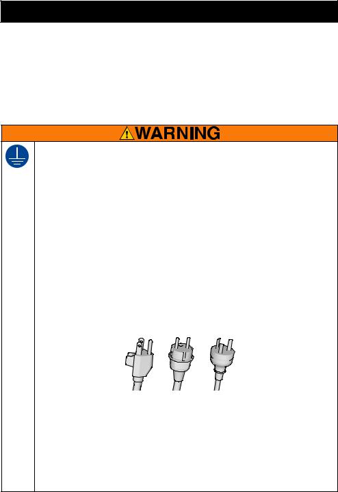
GROUNDING
This product must be grounded. In the event of an electrical short circuit, grounding reduces the risk of electric shock by providing an escape wire for the electric current. This product is equipped with a cord having a grounding wire with an appropriate grounding plug. The plug must be plugged into an outlet that is properly installed and grounded in accordance with all local codes and ordinances.
•Improper installation of the grounding plug is able to result in a risk of electric shock.
•When repair or replacement of the cord or plug is required, do not connect the grounding wire to either flat blade terminal.
•The wire with insulation having an outer surface that is green with or without yellow stripes is the grounding wire.
•Check witha qualified electricianorserviceman whenthe groundinginstructions are not completely understood, or when in doubt as to whether the product is properly grounded.
•Do not modify the plug provided; if it does not fit the outlet, have the proper outlet installed by a qualified electrician.
•This product is for use on a nominal 120V or 230V circuit and has a grounding plug similar to the plugs illustrated below.
120V 230V
ti24583a
•Only connect the product to an outlet having the same configuration as the plug.
•Do not use an adapter with this product.
Extension Cords:
•Use only a 3-wire extension cord that has a grounding plug and a grounding receptacle that accepts the plug on the product.
•Makesureyourextensioncordisnotdamaged.Ifanextensioncordisnecessary use 12 AWG (2.5mm2) minimum to carry the current that the product draws.
•An undersized cord results in a drop in line voltage and loss of power and overheating.
4 |
3A3258J |
Warnings
FIRE AND EXPLOSION HAZARD
Flammable fumes, such as solvent and paint fumes, in work area can ignite or explode. To help prevent fire and explosion:
• Do not spray or clean with flammable materials. Use water-based materials only.
• Use equipment only in well ventilated area.
• Sprayer generates sparks. When flammable liquids are used near the sprayer, keep sprayer at least 20 feet (6.1 meters) away from explosive vapors.
• Keep work area free of debris, including solvent, rags and gasoline.
•Ground all equipment in the work area. See Grounding instructions.
•Keep a working fire extinguisher in the work area.
EQUIPMENT MISUSE HAZARD
Misuse can cause death or serious injury.
•Always wear appropriate gloves, eye protection, and a respirator or mask when painting.
•Do not operate or spray near children. Keep children away from equipment at all times.
•Do not overreach or stand on an unstable support. Keep effective footing and balance at all times.
•Stay alert and watch what you are doing.
•Do not operate the unit when fatigued or under the influence of drugs or alcohol.
•Do not kink or over-bend the material or air hoses.
•Do not expose the hose to temperatures or to pressures in excess of those specified by Graco.
•Do not use the hose as a strength member to pull or lift the equipment.
•Do not alter or modify equipment. Alterations or modifications may void agency approvals and create safety hazards.
•Make sure all equipment is rated and approved for the environment in which you are using it.
BURN HAZARD
Equipment surfaces and fluid that is heated can become very hot during operation. To avoid severe burns:
• Do not touch hot fluid or equipment.
ELECTRIC SHOCK HAZARD
This equipment must be grounded. Improper grounding, setup, or usage of the system can cause electric shock.
•Turn off and disconnect power cord before servicing equipment.
•Connect only to grounded electrical outlets.
•Use only 3-wire extension cords.
•Ensure ground prongs are intact on power and extension cords.
•Do not expose to rain. Store indoors.
3A3258J |
5 |

Warnings
PRESSURIZED EQUIPMENT HAZARD
Fluid from the equipment, leaks, or ruptured components can splash in the eyes or on skin and cause serious injury.
• Follow the Pressure Relief Procedure when you stop spraying/dispensing and before cleaning, checking, or servicing equipment.
•Tighten all fluid connections before operating the equipment.
•Check hoses, tubes, and couplings daily. Replace worn or damaged parts immediately.
MOVING PARTS HAZARD
Moving parts can pinch, cut, or amputate fingers and other body parts.
• Keep clear of moving parts.
• Do not operate equipment with protective guards or covers removed.
•Pressurized equipment can start without warning. Before checking, moving, or servicing equipment, follow the Pressure Relief Procedure and disconnect all power sources.
PLASTIC PARTS CLEANING SOLVENT HAZARD
Many solvents can degrade plastic parts and cause them to fail, which could cause serious injury or property damage.
• Use only compatible water-based solvents to clean plastic structural or pressure-containing parts.
•See Technical Data in this and all other equipment instruction manuals. Read fluid and solvent manufacturer’s Safety Data Sheet (SDS) and recommendations.
PERSONAL PROTECTIVE EQUIPMENT
Wear appropriate protective equipment when in the work area to help prevent serious injury, including eye injury, hearing loss, inhalation of toxic fumes, and burns. This protective equipment includes but is not limited to:
•Protective eyewear, and hearing protection.
•Respirators, protective clothing, and gloves as recommended by the fluid and solvent manufacturer.
CALIFORNIA PROPOSITION 65
Thisproductcontains achemical known to the State ofCalifornia to cause cancer, birth defects or other reproductive harm. Wash hands after handling.
6 |
3A3258J |
Component Identification
Component Identification
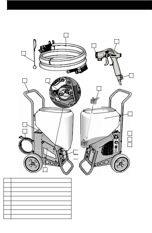
RTX1400si
|
P |
|
W |
|
S |
R |
|
|
Y |
A |
E |
|
N |
M
B
C


 H
H


 J
J


 K
K
F 


 G
G 


D
ti27337a
A |
Handle |
B |
Toolbox |
C |
Power Cord |
D |
Pump Access Panel |
E |
RotoFlex™ II Pump |
F |
Pump Hose Outlet |
G |
Air Hose Outlet |
H |
Material Flow Gauge |
J |
Material Flow Control |
K |
ON/OFF Switch |
M |
Material Hopper |
N |
Burp Guard |
P |
Material/Air Hose |
R |
Material Thickness Gauge |
S |
Nozzle |
W |
Gun |
Y |
Air control valve |
|
Model/Serial Tag (Not shown, located |
|
on bottom of unit.) |
3A3258J |
7 |

Component Identification
RTX2000pi & RTX2500pi
P |
W |
|
S |
R
Y
X
A |
N |
|
|
M |
B |
|
C |
H |
|
J |
|
K |
|
F |
G |
D |
ti27338a |
A |
Handle |
B |
Toolbox |
C |
Power Cord |
D |
Pump Access Panel |
E |
RotoFlex™ II Pump |
F |
Pump Hose Outlet |
G |
Air Hose Outlet |
H |
Material Flow Gauge |
J |
Material Flow Control |
K |
ON/OFF Switch |
M |
Material Hopper |
N |
Burp Guard |
P |
Material/Air Hose |
R |
Material Thickness Gauge |
S |
Nozzle & retaining ring |
W |
Gun |
X |
Prime Valve |
Y |
Air control valve |
|
Model/Serial Tag (Not shown, located |
|
on bottom of unit.) |
8 |
3A3258J |
Preparation
Preparation
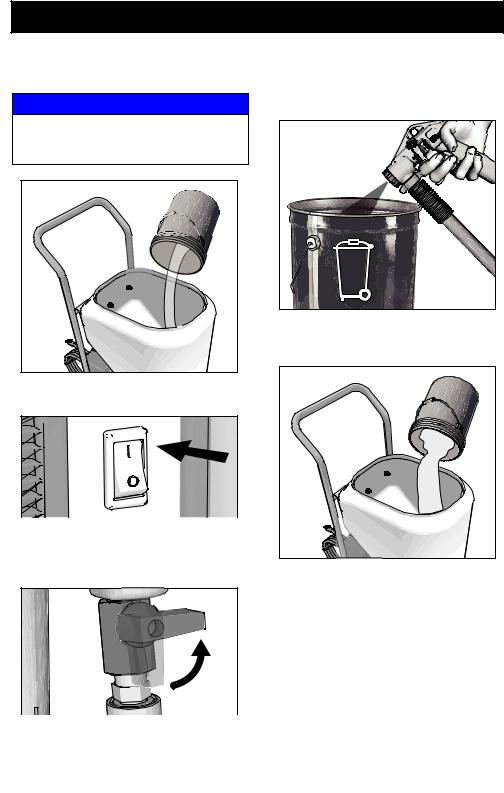
Pressure Relief Procedure
Follow the Pressure Relief Procedure whenever you see this symbol.
This equipment stays pressurized until pressure is manually relieved. To help prevent serious injury from pressurized fluid or splashed fluid follow the Pressure Relief Procedure whenever sprayer is stopped and before sprayer is cleaned or checked, and before equipment is serviced.
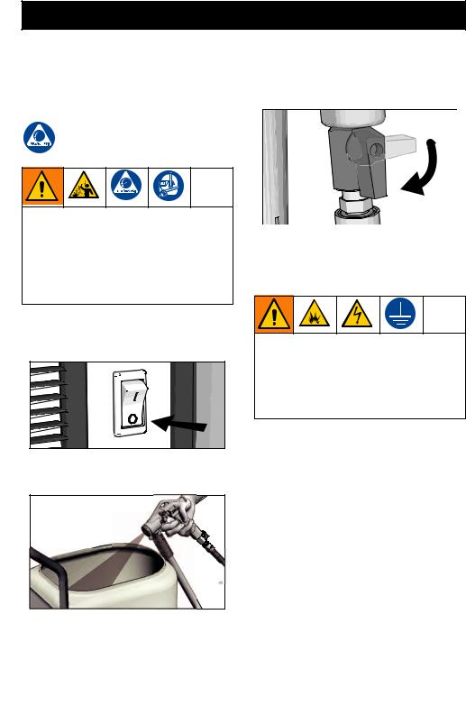
1.Turn ON/OFF switch to the OFF position. Wait 7 seconds for power to dissipate.
ti27340a

2.On the RTX1400si, trigger gun into material hopper.
ti27339a |
3.Open air control valve.
ti27341a
4.On the RTX2000pi and RTX2500pi, open gun prime valve.
Grounding
The equipment must be grounded to reduce the risk of static sparking and electric shock. An electric or static spark can cause fumes to ignite or explode. An improper ground can cause electric shock. Agood ground provides an escape wire for the electric current.
This sprayer includes a ground wire with an appropriate ground contact. The plug must be plugged into an outlet that is properly installed and grounded in accordance with all local codes and ordinances.
Do not modify the plug provided; if it does not fit the outlet, have the proper outlet installed by a qualified electrician.
Power Requirements
100-120V units require 100-120 VAC, 50/60 Hz, 12 or 15A, 1 phase. 230V units require 220-240 VAC, 50/60 Hz, 10A
Extension Cords
Use an extension cord with an undamaged ground contact. If an extension cord is necessary, use a 3-wire, 12 AWG (2.5 mm2) minimum.
3A3258J |
9 |

Preparation
NOTE: Lighter gauge or longer extension cords may reduce sprayer performance.
Auxiliary Air Compressor
Do not use an auxiliary air compressor with this spray system.
Generator Requirements
3500 W (3.5 kW) minimum.
Hose Size and Length
The system comes with a 25 ft (7.6m) hose set consisting of a 3/4 in. ID RTX1400si/1 in. ID RTX2000pi and RTX2500pi material hose and a 3/8 in-ID air hose.
Do not use more than 25 ft (7.6 m) of material hose.
Soft Start/Smart Start™ System (RTX2000pi and RTX2500pi only)
“Smart” vs. “Soft”
•“Smart” refers to the function where the motorstartsandstopswhenthetriggeris pulled and released. This keeps the sprayer at full operating pressure and allows the sprayer to spray immediately when the gun is triggered.
•“Soft” refers to the function where the sprayer slowly starts the pump. This prevents a large “splotch” of material from being discharged from the gun when trigger is pulled after the sprayer has sat idle for a period of time.
Smart Start
The Smart Start System is controlled by compressed air in the tanks and lines. When gun is triggered, air flows through the lines and opens a flow switch. There is also another pressure switch that senses when the compressed air system is at operating pressure. This second pressure switch allows the sprayer to start immediately when the sprayer is turned ON charging the compressed air system to full pressure. This method keeps the compressed air system at operating pressure if there is a small air leak in the system.
Soft Start
The Soft Start System is controlled by motor power and an air cylinder. When pressurized, the air cylinder pushes the rollers into the peristaltic pump pushing material through the pump. When the motor shuts off, a solenoid valve relieves the pressure in the air cylinder causing the rollers to disengage from the peristalticpump. When the motorstarts again there is a time delay while the air cylinders charge and move the rollers into the pump this is the “Soft Start”.
10 |
3A3258J |
Setup
Setup
NOTICE
•Do not store sprayer under pressure.
•Do not allow material to dry inside pump, hoses, gun or spray system.
•When operating a RTX1400SI and you are going to stop spraying for more than five minutes turn sprayer OFF to prevent shortened pump life.
1.Connect air hose and material hose to sprayer air and material hose outlets.
|
ti27342a |
2. |
Open air valve. |
4.Connect material hose to gun.
ti27344a |
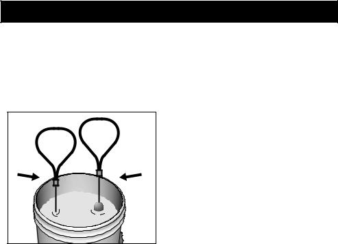
5.Make sure burp guard is installed.
Before adding material to the hopper, install the burp guard. When only a small amount of material remains in the hopper, the burp guard prevents material from shooting out when the unit is turned off. Thismaterialcouldsplashintheoperator’s eyes or on skin, or into the air.
ti27341a
3.Connect air hose to gun.
ti27343a |
3A3258J |
6.Install spray nozzle or wide spray disc. See Recommended Nozzle Selection Charts, page 15.
ti27345a |
11
Setup
7.Pour one gallon (four liters) of water into the material hopper.
NOTICE
To prevent pump damage, before adding material or starting unit in cold weather, run warm water through the pump.
ti27346a |
8.Turn ON/OFF switch to ON position.
ti27380a
9.Close gun air valve. On the RTX2000pi andRTX2500pi,opentheprimevalveon the gun.
ti27383a
10.Point gun into waste bucket and pull trigger to pump water through the system. Continue to trigger gun until material hopper is empty.
ti27381a |
11.Add pre-mixed texture mix to material hopper. See Mixing Material, page 13.
ti27382a |
12.Continue to trigger gun and spray into waste bucket until a steady stream of material sprays out of gun.
13.Release trigger.
IMPORTANT! Fluid/air flow will be restricted if the material/air hoses are restricted or kinked.
12 |
3A3258J |

Mixing Material
Mixing Material
NOTE: Correct material mixture is essential. The pump will not operate if the mixture is too thick.
•Mix the material in a separate container before pouring it into hopper.
•Use Material Thickness Gauge to determine if mixture is thin enough to spray.
•The Material Thickness Gauge will only determine if the material is thin enough to pass through the pump. For some applications or for higher speed spraying, your mixture may need to be thinner.
•For best results, do not use partial bags of material.
1.Mix the material and water in a separate container.
Dry Mix - 40 lb (18 kg) bag
Carefully mix texture material and water according to manufacturer instructions on bag.
MIX TEXTURE . lb 40


 5
5 GAL
GAL


ti2496b
Premix
Slowly add approximately 2 to 4 quarts (1.9 to 3.8 liters) of water to a 5 gallon (18.9 liter) bucket of premix.
PREMIX |
5 |
GAL |
ti2493b |
2.Agitate to mix,using a half-inch, variable speed drill with mixing paddle, to a smooth, lump-free consistency.
ti2497b
3.Allow ceiling texture to set for at least 15 minutes. Then remix prior to use.
4.After texture material is thoroughly mixed, gently set ball end of Material Thickness Gauge on surface of mixture.
3A3258J |
13 |
Mixing Material
NOTE:Foranaccuratetest,besuregaugeis completely dry and clean every time it is used.
5.Observe the ball on the material. When the material is thin enough to spray the ball will sink completely into the mixture within 10 seconds.
READY |
ADD |
WATER |
|
ti2498b |
|
6.If the ball does not sink completely into the mixture within 10 seconds, add more water, agitate and try test again.
7.Oncematerialismixedpourmaterialinto the sprayer hopper. See Operation, page15fornozzleselectionandsprayer adjustments.
14 |
3A3258J |
Loading...