


 Loading...
G500/G600 TXi
Part 23 AML STC
Maintenance Manual
Contains Instructions for Continued Airworthiness for STC SA02571SE
Aircraft make, model, registration number, and serial number, along with the applicable STC configuration information, must be completed in Appendix A and saved with aircraft permanent records.
190-01717-B1 |
October 2020 |
Revision 4 |

© 2020
Garmin International, Inc., or its subsidiaries All Rights Reserved
Except as expressly provided herein, no part of this manual may be reproduced, copied, transmitted, disseminated, downloaded, or stored in any storage medium, for any purpose without the express prior written consent of Garmin. Garmin hereby grants permission to download a single copy of this manual and of any revision to this manual onto a hard drive or other electronic storage medium to be viewed and to print one copy of this manual or of any revision hereto, provided that such electronic or printed copy of this manual or revision must contain the complete text of this copyright notice and provided further that any unauthorized commercial distribution of this manual or any revision hereto is strictly prohibited.
SkyWatch® and Stormscope® are registered trademarks of L-3 Communications. Ryan®, TCAD®, and Avidyne® are registered trademarks of Avidyne Corporation. AC-U-KWIK® is a registered trademark of Penton Business Media Inc. Bendix/King® and Honeywell® are registered trademarks of Honeywell International, Inc.
© 2020 SiriusXM Radio Inc. Sirius, XM and all related marks and logos are trademarks of SiriusXM Radio Inc. All other marks and logos are property of their respective owners. All rights reserved.
Garmin®, FliteCharts®, and SafeTaxi® are registered trademarks of Garmin International or its subsidiaries. Connext™, GDU™, GTN™, SVT™, and Telligence™ are trademarks of Garmin International or its subsidiaries. These trademarks may not be used without the express permission of Garmin.
The Bluetooth® word mark and logos are registered trademarks owned by Bluetooth SIG, Inc. and any use of such marks by Garmin is under license. Other trademarks and trade names are those of their respective owners.
ChartView™ is a trademark of Jeppesen, Inc.
Windows® is a registered trademark of Microsoft Corporation in the United States and other countries. © 2020 SD® is a registered trademark of SD-3C, LLC. All rights reserved.
Iridium® is a registered trademark of Iridium Communications, Inc. All rights reserved. The term Wi-Fi® is a registered trademark of the Wi-Fi Alliance®.
All other product or company names mentioned in this manual are trade names, trademarks, or registered trademarks of their respective owners.
For aviation product support, visit flyGarmin.com.
For information regarding the Aviation Limited Warranty, refer to Gamin's website.
190-01717-B1 |
G500/G600 TXi Part 23 AML STC Maintenance Manual |
Rev. 4 |
Page i |

INFORMATION SUBJECT TO EXPORT CONTROL LAWS
This document may contain information that is subject to the Export Administration Regulations (EAR) issued by the United States Department of Commerce (15 CFR, Chapter VII, Subchapter C) and may not be exported, released, or disclosed to foreign nationals inside or outside of the United States without first obtaining an export license.
The information in this document is subject to change without notice. For updates and supplemental information regarding the operation of Garmin products, visit flyGarmin.com.
Software License Notification
AES Encryption
The product may include AES file encryption software, © 2002 DR. Brian Gladman, subject to the following license:
The free distribution and use of this software in both source and binary form is allowed (with or without changes) provided:
•Distributions of this sourcecode includetheabove copyrightnotice, this listof conditions, and the following disclaimer.
•Distribution in binary form include the above copyright notice, this list of conditions, and the following disclaimer in the documentation and/or other associated materials.
•Thecopyrightholder’snameis notusedtoendorseproducts builtusingthis softwarewithoutspecificwritten permission.
Alternatively, provided this notice is retained in full, this product may be distributed under the terms of the GNU General Public License (GPL) in which case the provisions of the GPL apply instead of those given above.
Disclaimer
The AES file encryption software is provided “as is” with no explicit or implied warranties in respect of its properties, including, but not limited to, correctness and/or fitness for purpose.
190-01717-B1 |
G500/G600 TXi Part 23 AML STC Maintenance Manual |
Rev. 4 |
Page ii |

SOFTWARE LICENSE AGREEMENT FOR GARMIN AVIATION PRODUCTS
The software embedded in your Garmin product (the “Licensed Software”) is owned by Garmin International, Inc. (“Garmin” or “us”). The Licensed Software is protected under copyright laws and international copyright treaties. The Licensed Software is provided under this Software License Agreement (hereinafter the “Agreement”) and is subject to the following terms and conditions which are agreed to by End User (“Licensee”, “you” or “your”), on the one hand, and Garmin and its licensors and affiliated companies of Garmin and its licensors, on the other hand. The Licensed Software is licensed, not sold, to you. Garmin and Licensee may be referred to individually as a “Party” or jointly as the “Parties.”
IMPORTANT: CAREFULLY READ THIS ENTIRE AGREEMENT BEFORE USING THIS PRODUCT. INSTALLING, COPYING, OR OTHERWISE USING THIS PRODUCT INDICATES YOUR ACKNOWLEDGMENT THAT YOU HAVE READ THIS AGREEMENT AND AGREE TO ITS TERMS AND CONDITIONS. IF YOU DO NOT AGREE TO THESE TERMS AND CONDITIONS, YOU MAY NOT USE THIS PRODUCT.
1.Definitions. The following capitalized terms shall have the meanings set forth below:
a.“Device” means any Garmin device that is delivered by or on behalf of Garmin to Licensee onto which the Licensed Software is installed.
b.“Documentation” means Gamin's then-current instructional, technical or functional documentation relating to the Devices or Licensed Software which is delivered or made available by Garmin in connection with thisAgreement.
c.“Licensed Software” means the software in binary executable form that is embedded in the Devices and/or made available for use on the Devices via a software loader card.
d.“Permitted Purpose” means operating and using the Device on which the Licensed Software is installed for the Device's intended use.
2.License.
a.License Grant. Subject to the terms and conditions of thisAgreement and Licensee's compliance with the terms and conditions of thisAgreement, Garmin hereby grants to Licensee a limited, royalty-free, non-exclusive, non-sublicenseable, non-transferable and revocable right and license to use and perform the Licensed Software as installed on the Devicesandthe Documentation solelyfor the Permitted Purpose and onlyduring the termof thisAgreement, provided that the Licensed Software may only be used by Licensee on Devices on which the Licensed Software has been installed or otherwise made available by Garmin.
b.Reservation of Rights. Garmin retains exclusive ownership of all right, title and interest in and to the Licensed Software and Documentation. All of Gamin's rights in and to the Licensed Software and Documentation not expressly licensed to Licensee under Section 2.1 are expressly reserved for Garmin. Nothing contained in thisAgreement shall be construed as conferring by implication, acquiescence, or estoppel any license or other right upon Licensee. Without limiting the foregoing, the Parties acknowledge and agree that this Agreement grants Licensee a license of the Licensed Software under the terms of Section 2.1, and shall not in any manner be construed as a sale of the Licensed Software or any rights in the Licensed Software.
190-01717-B1 |
G500/G600 TXi Part 23 AML STC Maintenance Manual |
Rev. 4 |
Page iii |

3.Restrictions; Protection and Third Party Devices.
a.Prohibited Uses. Licensee shall not, shall not attempt to and shall not permit any third party to:
(a) sublicense, lease, loan, sell, resell, market, transfer, rent, disclose, demonstrate, or distribute the Licensed Software or Documentation to any third party; (b) uninstall the Licensed Software from the Device on which it was originally installed; (c) make any use of or perform any acts with respect to the Licensed Software or Documentation other than as expressly permitted in accordance with the terms of thisAgreement; (d) use the Licensed Software or Documentation in any manner that violates any applicable law; (e) reproduce or copy the Licensed Software; (f) modify, adapt, alter, translate, port, create derivative works of, reverse engineer, decompile or disassemble the Licensed Software or Documentation or otherwise derive the source code or other proprietary information or trade secrets from the Licensed Software; (g) remove, alter, or obscure any proprietary notices from the Licensed Software or Documentation; (h) use the Licensed Software or Documentation to provide servicesto third parties(suchas business process outsourcing, service bureauapplicationsor third party training); (i) use the Licensed Software on any equipment, hardware or device other than a Device; or (j) export, re-export or otherwise distribute, directly or indirectly, the Licensed Software or Documentation to a jurisdiction or country to which the export, reexport or distribution of such Licensed Software or Documentation is prohibited by applicable law.
b.Protection of Software and Documentation. Licensee shall use its best efforts to protect the LicensedSoftware andDocumentation fromunauthorizedaccess, distribution, modification, display, reproduction, disclosure or use with at least the same degree of care as Licensee normally uses in protecting its own software and documentation of a similar nature from unauthorized access, distribution, modification, display, reproduction, disclosure or use. Licensee shall limit access to the Licensed Software and Documentation to only those employees of Licensee who require access to the Licensed Software or Documentation for the Permitted Purpose and who have been made aware of the restrictions set forth in this Agreement. Licensee shall take prompt and appropriate action to prevent unauthorized use or disclosure of the Licensed Software and Documentation.
4.Term and Termination.
a.Term. The term of thisAgreement shall commence on the Effective Date, and shall continue in perpetuity thereafter, unless terminated earlier as provided in this Section 4.
b.Termination by Garmin. Garmin may immediately terminate thisAgreement upon written notice to Licensee if Licensee commits a material breach of thisAgreement or breaches a material term of thisAgreement.
c.Effect of Termination. Upon any termination of thisAgreement for any Party: (a) Licensee shall immediately cease all use of the Licensed Software and Documentation; (b) all rights and licenses granted to Licensee to the Licensed Software and Documentation and Gamin's related obligations shall immediately terminate; and (c) Sections 4.3, 5 and 6 shall survive.
190-01717-B1 |
G500/G600 TXi Part 23 AML STC Maintenance Manual |
Rev. 4 |
Page iv |

5.Disclaimer; Limitations of Liability; Indemnity.
a.DISCLAIMER. TO THE MAXIMUM EXTENT PERMITTED BYAPPLICABLE LAW, THE LICENSED SOFTWAREAND DOCUMENTATION (INCLUDINGANY RESULTS TO BE OBTAINED FROMANY USE OF THE LICENSED SOFTWAREAND DOCUMENTATION)ARE PROVIDED “AS IS” AND “ASAVAILABLE” WITH NO WARRANTIES, GUARANTEES OR REPRESENTATIONS AND NEITHER GARMIN NOR ITSAFFILIATES MAKEANY REPRESENTATION, WARRANTY OR GUARANTEE, STATUTORY OR OTHERWISE, UNDER LAW OR FROM THE COURSE OF DEALING OR USAGE OF TRADE, EXPRESS OR IMPLIED, INCLUDINGANYWARRANTIES OF MERCHANTABILITY, FITNESS FORA PARTICULAR PURPOSE, NON-INTERFERENCE, NON-INFRINGEMENT, TITLE, OR SIMILAR, UNDER THE LAWS OFANY JURISDICTION. GARMIN DOES NOT WARRANTTHAT THE LICENSED SOFTWARE OR DOCUMENTATION WILL MEET LICENSEE'S REQUIREMENTS OR THAT OPERATION OF THE SOFTWARE WILL BE UNINTERRUPTED OR ERROR FREE. LICENSEEASSUMES THE ENTIRE RISK AS TO THE QUALITYAND PERFORMANCE OF THE LICENSED SOFTWAREAND DOCUMENTATION. THE LICENSED SOFTWARE IS NOT INTENDED FOR USE IN ANY NUCLEAR, MEDICAL, OR OTHER INHERENTLY DANGEROUS APPLICATIONS,AND GARMIN DISCLAIMSALL LIABILITY FORANY DAMAGE OR LOSS CAUSED BY SUCH USE OF THE LICENSED SOFTWARE.
b.EXCLUSION OF DAMAGES; LIMITATION OF LIABILITY. NOTWITHSTANDING ANYTHING TO THE CONTRARY HEREIN, TO THE MAXIMUM EXTENT PERMITTED BYAPPLICABLE LAW, UNDER NO CIRCUMSTANCESAND REGARDLESS OF THE NATURE OF ANY CLAIM SHALL GARMIN BE LIABLE TO LICENSEE FOR ANAMOUNT IN EXCESS OF USD $100, OR BE LIABLE INANY AMOUNT FOR ANY SPECIAL, INCIDENTAL, CONSEQUENTIAL, PUNITIVE OR INDIRECT DAMAGES, LOSS OF GOODWILLOR PROFITS, LIQUIDATED DAMAGES, DATALOSS, COMPUTER FAILURE OR MALFUNCTION,ATTORNEYS' FEES, COURT COSTS, INTEREST OR EXEMPLARY OR PUNITIVE DAMAGES, ARISING OUT OF OR IN CONNECTION WITH THE USE OR PERFORMANCE OR NON-PERFORMANCE OF THE LICENSED SOFTWARE OR DOCUMENTATION, EVEN IF GARMIN HAS BEENADVISED OF THE POSSIBILITY OF SUCH LOSS OR DAMAGES.
c.Indemnity. Licensee shall indemnify, defend and hold Garmin and its affiliates harmless against any and all losses, claims, actions, causes of action, liabilities, demands, fines, judgments, damagesand expenses suffered or incurred by Garminor itsaffiliatedcompanies in connection with: (a) any use or misuse of the Licensed Software or Documentation by Licensee or any third party in Licensee's reasonable control; or
(b) Licensee's breach of thisAgreement.
190-01717-B1 |
G500/G600 TXi Part 23 AML STC Maintenance Manual |
Rev. 4 |
Page v |

6.General.
a.No Devices or Services. Licensee acknowledges and agrees that nothing in thisAgreement shall be construed as requiring Garmin to: (a) provide or supply the Devices or any other devices or hardware to Licensee; (b) grant any licenses to any software other than the Licensed Software; or (c) provide any services, such as support, maintenance, installation or professional services for the Licensed Software.
b.Non-Exclusive. Each Party's rights and obligations under thisAgreement are non-exclusive. Garmin is not precluded from marketing, licensing, providing, selling or distributing the Licensed Software or Documentation, or any other products, software, documentation or services, either directly or through any third party.
c.Assignment. Licensee may not assign thisAgreement or any of its rights, interests or obligations hereunder without the prior written consent of Garmin.Any purported assignment in violation of this Section 6.3 shall be null and void. Subject to the foregoing, thisAgreement shall be binding upon and shall inure to the benefit of the Parties and their respective successors and permitted assigns and transferees.
d.Feedback and Data. Licensee may from time to time provide feedback, comments, suggestions, questions, ideas, or other information to Garmin concerning the Licensed Software or Documentation or Gamin's products, services, technology, techniques, processes or materials (“Feedback”). Garmin may in connection with any of its products or servicesfreely use, copy, disclose, license, distribute and otherwise exploit suchFeedbackin any manner without any obligation, payment, royalty or restriction whether based on intellectual property rights or otherwise.
e.Governing Law. The validity, interpretation and enforcement of thisAgreement will be governedby the substantive laws, butnotthe choice of law rules, of the state of Kansas. This Agreement shall not be governed by the 1980 UN Convention on Contracts for the International Sale of Goods.
f.Legal Compliance. You represent and warrant that (i) you are not located in a country that is subject to a U.S. Government embargo, or has been designated by the U.S. Government as a “terrorist supporting” country, and (ii) you are not listed on any U.S. Government list of prohibited or restricted parties.
g.Injunctive Relief. The Parties acknowledge and agree that irreparable damage would occur if any provision of thisAgreement was not performed in accordance with its specific terms or was otherwise breached and as such, the Parties will be entitled to an injunction or injunctions to prevent breaches of thisAgreement and to enforce specifically the performance of the termsandprovisions of thisAgreement without proof of actual damages, this being in addition to any other remedy to which any Party is entitled at law or in equity.
h.Amendments and Waivers. ThisAgreement may be amended and any provision of this Agreement may be waived, provided that any such amendment or waiver will become and remain binding upon a Party only if such amendment or waiver is set forth in a writing by such Party. No course of dealing between or among any persons having any interest in this Agreement will be deemed effective to modify, amend or discharge any part of this Agreement or any rights or obligations of any Party under or by reason of thisAgreement. No delay or failure in exercising any right, power or remedy hereunder will affect or operate as a waiver thereof; nor will any single or partial exercise thereof or any abandonment or discontinuance of steps to enforce such a right, power or remedy preclude any further exercise thereof or of any other right, power or remedy. The rights and remedies hereunder
190-01717-B1 |
G500/G600 TXi Part 23 AML STC Maintenance Manual |
Rev. 4 |
Page vi |

are cumulative and not exclusive of any rights or remedies that any Party would otherwise have.
i.Severability. The provisions of thisAgreement will be severable in the event that for any reason whatsoever any of the provisions hereof are invalid, void or otherwise unenforceable, any such invalid, void or otherwise unenforceable provisions will be replaced by other provisions which are as similar as possible in terms to such invalid, void or otherwise unenforceable provisions but are valid and enforceable and the remaining provisions will remain valid and enforceable to the fullest extent permitted by applicable law, in each case so as to best preserve the intention of the Parties with respect to the benefits and obligations of thisAgreement.
j.No Third-Party Beneficiaries. ThisAgreement is solely for the benefit of the Parties and does not confer on third parties any remedy, claim, reimbursement, claim of action or other right in addition to those existing without reference to thisAgreement.
k.EntireAgreement. ThisAgreement shall constitute the entire agreement between Garmin and you with respect to the subject matter hereof and will supersede all prior negotiations, agreements and understandings of Garmin and you of any nature, whether oral or written, with respect to such subject matter.
l.Interpretation. In thisAgreement: (a) headings are for convenience only and do not affect the interpretation of thisAgreement; (b) the singular includes the plural and vice versa; (c) the words 'such as', 'including', 'particularly' and similar expressions are not used as, nor are intended to be, interpreted as words of limitation; (d) a reference to a person includes a natural person, partnership, joint venture, government agency, association, corporation or other body corporate; a thing includes a part of that thing; and a party includes its successors and permitted assigns; and (e) no rule of construction applies to the disadvantage of a Party because that Party was responsible for the preparation of thisAgreement.Any translation of thisAgreement from English is provided as a convenience only. If thisAgreement is translated into a language other than English and there is a conflict of terms between the English version and the other language version, the English version will control.
190-01717-B1 |
G500/G600 TXi Part 23 AML STC Maintenance Manual |
Rev. 4 |
Page vii |

|
|
RECORD OF REVISIONS |
Revision |
Revision Date |
Description |
1 |
11/17/17 |
Initial release. |
208/15/2018 Revised to address changes for the version 2.20 STC update.
306/25/19 Revised to address changes for the version 3.00 STC update.
4 10/26/20 Revised to address changes for the version 3.12 STC update.
|
DESCRIPTION OF CHANGES |
|
Section |
Description |
|
All |
Updated applicable references of “GMU 44” to “GMU 44(B)” to include GMU 44B. |
|
1.7.1 |
Added statement for GMU 44(B) references. |
|
Added statement for GEA 110/71B Enhanced references. |
||
|
2.1.3Added description of new aircraft timers.
2.1.7Differentiated GEA 71B Enhanced -02 and added -05 to Table 2-2 G500/G600 TXi LRU Electrical Load.
2.2.11Added Section 2.2.11 GMU 44B Magnetometer.
2.2.13Added statement about GBB 54 not being available for new installations.
2.2.17.1Added new EIS annunciator to Figure 2-20 Engine Annunciators.
3.1Updated wording of Airworthiness Limitations FAA statement.
4.2.9Updated GEA 71B Enhanced pinout table to include -05 pinout list.
4.2.12Added Section 4.2.12 GMU 44B.
5.3Added removal and re-installation sections for separate EIS annunciators.
5.10Added Figure 5-19 GMU 44B Installation (Universal Mount Example).
5.13.3Updated pressure ceiling for brass pressure sensors to 32,000 feet.
5.14.5
Clarified that battery should not be connected to ground power during rundown test.
Clarified how to verify a backup battery rundown test PASS was achieved. A.2 Updated fillable form to include GMU 44B.
A.3 Updated fillable form to include GMU 44B.
190-01717-B1 |
G500/G600 TXi Part 23 AML STC Maintenance Manual |
Rev. 4 |
Page viii |
DEFINITIONS OF WARNINGS, CAUTIONS, AND NOTES
WARNING
Warnings indicate that injury or death is possible if the instructions are disregarded.
CAUTION
Cautions indicate that damage to the equipment is possible.
NOTE
Notes provide additional information.
WARNING
This product, its packaging, and its components contain chemicals known to the State of California to cause cancer, birth defects, or reproductive harm. This notice is being provided in accordance with California's Proposition 65. For questions or additional information, refer to www.garmin.com/prop65.
WARNING
Perchlorate Material – special handling may apply.
Refer to www.dtsc.ca.gov/hazardouswaste/perchlorate.
WARNING
Failure to properly configure the EIS gauges per the POH/AFM and other approved data could result in serious injury, damage to equipment, or death.
CAUTION
To avoid damage to the GDU 700/1060, take precautions to prevent electrostatic discharge (ESD) when handling the unit, connectors, and associated wiring. ESD damage can be prevented by touching an object of the same electrical potential as the unit before handling the unit itself.
CAUTION
The GDU 700/1060 has a special anti-reflective coated display that is sensitive to skin oils, waxes, and abrasive cleaners. CLEANERS CONTAINING AMMONIA WILL HARM THE ANTI-REFLECTIVE COATING. Clean the display with a clean, lint-free cloth, and a cleaner that is safe for anti-reflective coatings.
CAUTION
Do not store any G500/G600 TXi components in or near water.
190-01717-B1 |
G500/G600 TXi Part 23 AML STC Maintenance Manual |
Rev. 4 |
Page ix |
|
|
TABLE OF CONTENTS |
|
|
1 |
INTRODUCTION ............................................................................................................... |
|
1-1 |
|
|
1.1 |
Purpose....................................................................................................................................... |
|
1-2 |
|
1.2 |
Scope.......................................................................................................................................... |
|
1-2 |
|
1.3 |
Organization............................................................................................................................... |
|
1-2 |
|
1.4 |
Applicability............................................................................................................................... |
|
1-2 |
|
1.5 |
Publications................................................................................................................................ |
|
1-3 |
|
1.6 |
Revision and Distribution........................................................................................................... |
|
1-3 |
|
1.7 |
Terminology and Acronyms....................................................................................................... |
|
1-3 |
2 |
SYSTEM DESCRIPTION .................................................................................................. |
|
2-1 |
|
|
2.1 |
System Overview....................................................................................................................... |
|
2-2 |
|
2.2 |
LRU Description, Control, and Operation................................................................................. |
2-7 |
|
3 INSTRUCTIONS FOR CONTINUED AIRWORTHINESS .......................................... |
3-1 |
|||
|
3.1 |
Airworthiness Limitations.......................................................................................................... |
|
3-2 |
|
3.2 |
Servicing Information ................................................................................................................ |
|
3-2 |
|
3.3 |
Maintenance Intervals................................................................................................................ |
|
3-3 |
|
3.4 |
Visual Inspection........................................................................................................................ |
|
3-5 |
|
3.5 |
Electrical Bonding Check........................................................................................................... |
|
3-6 |
|
3.6 |
RVSM Periodic Maintenance (Socata TBM 700/850 Only) ..................................................... |
3-7 |
|
|
3.7 |
Overhaul Period.......................................................................................................................... |
|
3-7 |
|
3.8 |
Special Inspection Requirements............................................................................................... |
|
3-8 |
|
3.9 |
Application of Protective Treatments ........................................................................................ |
3-9 |
|
|
3.10 |
Data Relative to Structural Fasteners......................................................................................... |
3-9 |
|
|
3.11 |
Additional Instructions............................................................................................................... |
|
3-9 |
4 |
TROUBLESHOOTING ...................................................................................................... |
|
4-1 |
|
|
4.1 |
General System Troubleshooting............................................................................................... |
|
4-2 |
|
4.2 |
Connector Information............................................................................................................... |
|
4-3 |
|
4.3 |
Troubleshooting Flow Charts................................................................................................... |
|
4-30 |
5 EQUIPMENT MAINTENANCE AND CHECKOUT PROCEDURES......................... |
5-1 |
|||
|
5.1 |
GDU 700/1060........................................................................................................................... |
|
5-3 |
|
5.2 |
GCU 485 .................................................................................................................................. |
|
5-11 |
|
5.3 |
EIS Annunciator....................................................................................................................... |
|
5-13 |
|
5.4 |
GDC 72 ................................................................................................................................... |
|
5-15 |
|
5.5 |
GSU 75( ), GRS 79 .................................................................................................................. |
|
5-17 |
|
5.6 |
GAD 43/43e ............................................................................................................................. |
|
5-19 |
|
5.7 |
GEA 110................................................................................................................................... |
|
5-21 |
|
5.8 |
GEA 71B Enhanced................................................................................................................. |
|
5-24 |
|
5.9 |
GBB 54..................................................................................................................................... |
|
5-27 |
|
5.10 |
GMU 44(B).............................................................................................................................. |
|
5-30 |
|
5.11 |
GTP 59 ..................................................................................................................................... |
|
5-33 |
|
5.12 |
Backup GPS Antenna............................................................................................................... |
|
5-35 |
|
5.13 |
EIS Sensors .............................................................................................................................. |
|
5-37 |
|
5.14 |
Calibration................................................................................................................................ |
|
5-45 |
|
5.15 |
Uploading Software.................................................................................................................. |
|
5-47 |
|
5.16 |
System Checks ......................................................................................................................... |
|
5-48 |
APPENDIX A INSTALLATION-SPECIFIC INFORMATION ......................................... |
A-1 |
|||
|
A.1 |
General Information.................................................................................................................. |
|
A-1 |
|
A.2 |
LRU Information....................................................................................................................... |
|
A-2 |
|
A.3 |
Equipment Location.................................................................................................................. |
|
A-3 |
190-01717-B1 |
G500/G600 TXi Part 23 AML STC Maintenance Manual |
|||
Rev. 4 |
|
|
Page x |
|

A.4 |
Wire Routing - Single Engine................................................................................................... |
A-4 |
A.5 |
Wire Routing - Twin Engine..................................................................................................... |
A-5 |
A.6 |
Saved Configuration File .......................................................................................................... |
A-6 |
A.7 |
Print Configuration Log............................................................................................................ |
A-6 |
A.8 |
GDU 1060 EIS Gauge Layout Template.................................................................................. |
A-7 |
A.9 |
GDU 700P EIS Gauge Layout Template.................................................................................. |
A-8 |
A.10 |
GDU 700L EIS Gauge Layout Template................................................................................ |
A-10 |
190-01717-B1 |
G500/G600 TXi Part 23 AML STC Maintenance Manual |
Rev. 4 |
Page xi |

LIST OF FIGURES
Figure 2-1 Entering the Configuration Mode on the GDU ................................................................... |
2-4 |
||
Figure 2-2 GDU 700P Display Configurations..................................................................................... |
2-7 |
||
Figure 2-3 GDU 700P Features and Controls ....................................................................................... |
2-8 |
||
Figure 2-4 GDU 700L Display Configurations..................................................................................... |
2-9 |
||
Figure 2-5 GDU 700L Features and Controls..................................................................................... |
2-10 |
||
Figure 2-6 GDU 1060 Display Configurations................................................................................... |
2-11 |
||
Figure 2-7 GDU 1060 Features and Controls...................................................................................... |
2-12 |
||
Figure 2-8 |
GCU 485............................................................................................................................ |
|
2-13 |
Figure 2-9 |
Garmin Backup GPS Antenna........................................................................................... |
|
2-13 |
Figure 2-10 |
GSU 75( ) ADAHRS Unit................................................................................................. |
|
2-14 |
Figure 2-11 |
GRS 79 AHRS Unit........................................................................................................... |
|
2-14 |
Figure 2-12 |
GDC 72 ADC Unit ............................................................................................................ |
|
2-15 |
Figure 2-13 |
GMU 44 Magnetometer..................................................................................................... |
|
2-15 |
Figure 2-14 |
GMU 44B Magnetometer.................................................................................................. |
|
2-15 |
Figure 2-15 |
GTP 59 Outside Air Temperature Probe........................................................................... |
2-16 |
|
Figure 2-16 |
GBB 54 Backup Battery.................................................................................................... |
|
2-16 |
Figure 2-17 |
GEA 110 Engine Interface................................................................................................. |
|
2-16 |
Figure 2-18 |
GEA 71B Enhanced Engine .............................................................................................. |
|
2-17 |
Figure 2-19 |
GAD 43 (Left) and GAD 43e (Right)................................................................................ |
2-17 |
|
Figure 2-20 |
Engine Annunciators ......................................................................................................... |
|
2-18 |
Figure 2-21 |
Carburetor Temperature Probe.......................................................................................... |
2-18 |
|
Figure 2-22 |
Oil Temperature Probe ...................................................................................................... |
|
2-18 |
Figure 2-23 |
Fuel Flow Sensor FT-60 (Left) and FT-90 (Right) ........................................................... |
2-19 |
|
Figure 2-24 |
Brass Pressure Sensor........................................................................................................ |
|
2-19 |
Figure 2-25 |
Stainless Steel Pressure Sensor.......................................................................................... |
2-19 |
|
Figure 4-1 62 Pin D-sub Connectors Numbering Scheme for Female/Male Contacts ......................... |
4-3 |
||
Figure 4-2 |
GDU 700P Connectors........................................................................................................ |
|
4-4 |
Figure 4-3 GCU 485 Connector............................................................................................................ |
|
4-9 |
|
Figure 4-4 |
View of J721 Connector Looking at GDC 72................................................................... |
4-10 |
|
Figure 4-5 |
View of J751 Connector Looking at GSU 75( )................................................................ |
4-12 |
|
Figure 4-6 |
View of J791 Connector Looking at GRS 79.................................................................... |
4-14 |
|
Figure 4-7 |
GAD 43/43e J431/P431 Connector Looking at Unit......................................................... |
4-16 |
|
Figure 4-8 |
GAD 43e J432/P432 Connector Looking at Unit.............................................................. |
4-18 |
|
Figure 4-9 |
GAD 43e J433/P433 Connector Looking at Unit.............................................................. |
4-20 |
|
Figure 4-10 |
GEA 110 Connectors......................................................................................................... |
|
4-21 |
Figure 4-11 |
GEA 110 J1101/P1101 Connector Looking at Unit.......................................................... |
4-21 |
|
Figure 4-12 |
GEA 110 J1102/P1102 Connector Looking at Unit.......................................................... |
4-22 |
|
Figure 4-13 |
GEA 71B Enhanced Connectors ....................................................................................... |
4-24 |
|
Figure 4-14 |
GBB 54 J541/P541 Connector........................................................................................... |
|
4-27 |
Figure 4-15 |
J441/P441 Connector Looking at Pigtail........................................................................... |
4-28 |
|
Figure 4-16 |
J442/P442 Connector Looking at Pigtail........................................................................... |
4-29 |
|
Figure 4-17 |
GDU Alert Message Troubleshooting............................................................................... |
4-31 |
|
Figure 4-18 |
GDU Config and Battery Alert Message Troubleshooting ............................................... |
4-32 |
|
Figure 4-19 |
PFD Alert Message Troubleshooting................................................................................ |
4-33 |
|
Figure 4-20 |
AHRS/ADC Alert Message Troubleshooting ................................................................... |
4-34 |
|
Figure 4-21 Terrain Alert Message Troubleshooting............................................................................ |
4-35 |
||
Figure 4-22 Traffic Alert Message Troubleshooting............................................................................. |
4-36 |
||
Figure 4-23 Audio/Weather Alert Message Troubleshooting............................................................... |
4-37 |
||
190-01717-B1 |
G500/G600 TXi Part 23 AML STC Maintenance Manual |
||
Rev. 4 |
|
|
Page xii |

Figure 4-24 |
External LRU Failure Message Troubleshooting.............................................................. |
4-38 |
Figure 4-25 |
External LRU Service Message Troubleshooting ............................................................. |
4-39 |
Figure 4-26 |
GAD Fault Message Troubleshooting............................................................................... |
4-40 |
Figure 4-27 |
GAD Fault Message Troubleshooting Continued ............................................................. |
4-41 |
Figure 4-28 |
EIS Gauge Troubleshooting .............................................................................................. |
4-42 |
Figure 5-1 |
GDU 1060 Installation......................................................................................................... |
5-3 |
Figure 5-2 |
GDU 700P Installation ........................................................................................................ |
5-4 |
Figure 5-3 |
Integrated ADC Module Installation................................................................................... |
5-7 |
Figure 5-4 |
Configuration Module Installation ...................................................................................... |
5-8 |
Figure 5-5 |
GCU 485 Installation......................................................................................................... |
5-11 |
Figure 5-6 |
Panel Cutout for GCU 485 ................................................................................................ |
5-12 |
Figure 5-7 |
EIS Caution and Warning Annunciator Installation.......................................................... |
5-13 |
Figure 5-8 |
Separate EIS Annunciator Installation............................................................................... |
5-14 |
Figure 5-9 |
GDC 72 Installation (Sheet Metal Shelf Example)........................................................... |
5-15 |
Figure 5-10 |
GSU 75( ) Installation (Sheet Metal Shelf Example)........................................................ |
5-17 |
Figure 5-11 |
GAD 43 Installation (Sheet Metal Shelf Example)........................................................... |
5-19 |
Figure 5-12 |
GEA 110 Installation (Mounted Directly to Airframe Example)...................................... |
5-21 |
Figure 5-13 |
GEA 110 Installation (Mounted on a Tray Example) ....................................................... |
5-22 |
Figure 5-14 |
GEA 71B Enhanced (Metallic Example) .......................................................................... |
5-24 |
Figure 5-15 |
GEA 71B Enhanced (Sandwich Panel Example).............................................................. |
5-25 |
Figure 5-16 |
GBB 54 Installation (Sheet Metal Shelf Example)............................................................ |
5-27 |
Figure 5-17 |
GBB 54 Battery Cell Replacement.................................................................................... |
5-29 |
Figure 5-18 |
GMU 44 Installation (Universal Mount Example)............................................................ |
5-31 |
Figure 5-19 GMU 44B Installation (Universal Mount Example)......................................................... |
5-32 |
|
Figure 5-20 GTP 59 Installation (Aircraft with Metallic Skin Example) ............................................. |
5-33 |
|
Figure 5-21 Backup GPS Antenna Installation (Non-removable Installation Example)...................... |
5-35 |
|
Figure 5-22 Backup GPS Antenna Installation (Removable Installation Example)............................. |
5-36 |
|
Figure 5-23 Carburetor Temperature Sensor Installation Example ...................................................... |
5-38 |
|
Figure 5-24 Oil Temperature Sensor Installation Example................................................................... |
5-39 |
|
Figure 5-25 |
Brass Sensor Installation (Coupling Mount Example)...................................................... |
5-41 |
Figure 5-26 |
Stainless Steel Sensor Installation (Housing Mount Example)......................................... |
5-42 |
Figure 5-27 |
Fuel Flow Transducer Installation..................................................................................... |
5-44 |
Figure 5-28 |
Airspeed Configuration Type............................................................................................ |
5-49 |
Figure A-1 GDU 1060 EIS Gauge Template........................................................................................ |
A-7 |
|
Figure A-2 GDU 700P EIS Gauge Layout Template............................................................................ |
A-8 |
|
Figure A-3 GDU 700P MFD/EIS Gauge Layout Template.................................................................. |
A-9 |
|
Figure A-4 GDU 700L EIS Gauge Layout Template......................................................................... |
A-10 |
|
Figure A-5 GDU 700L MFD/EIS Gauge Layout Template................................................................ |
A-11 |
|
190-01717-B1 |
G500/G600 TXi Part 23 AML STC Maintenance Manual |
Rev. 4 |
Page xiii |

LIST OF TABLES
Table 1-1 |
Reference Documentation ................................................................................................... |
1-3 |
Table 2-1 |
AML STC Installed Sensors................................................................................................ |
2-3 |
Table 2-2 |
G500/G600 TXi LRU Electrical Load ................................................................................ |
2-6 |
Table 3-1 |
Periodic Maintenance .......................................................................................................... |
3-3 |
Table 3-2 |
Electrical Bonding Requirements........................................................................................ |
3-6 |
Table 4-1 |
G500/G600 TXi Failures..................................................................................................... |
4-2 |
Table 4-2 |
G500/G600 TXi - GDU 700/1060 Connectors.................................................................... |
4-4 |
Table 4-3 |
G500/G600 TXi - GCU 485 Connectors............................................................................. |
4-9 |
Table 4-4 |
G500/G600 TXi - GDC 72 Connectors............................................................................. |
4-10 |
Table 4-5 |
G500/G600 TXi - GSU 75 Connectors ............................................................................. |
4-12 |
Table 4-6 |
G500/G600 TXi - GRS 79 Connectors.............................................................................. |
4-14 |
Table 4-7 |
G500/G600 TXi - GAD 43 Connectors............................................................................. |
4-16 |
Table 4-8 |
G500/G600 TXi - GAD 43e Connectors........................................................................... |
4-18 |
Table 4-9 |
G500/G600 TXi - GEA 110 Connectors........................................................................... |
4-21 |
Table 4-10 |
G500/G600 TXi - GEA 71B Enhanced Connectors.......................................................... |
4-24 |
Table 4-11 |
G500/G600 TXi - GBB 54 Connectors............................................................................. |
4-27 |
Table 4-12 |
G500/G600 TXi - GMU 44 Connectors............................................................................ |
4-28 |
Table 4-13 |
G500/G600 TXi - GMU 44B Connectors ......................................................................... |
4-29 |
Table 5-1 |
Pressure Sensor Equipment List........................................................................................ |
5-40 |
Table 5-2 |
LRU Status Indicators........................................................................................................ |
5-48 |
Table 5-3 |
Airspeed Test Points.......................................................................................................... |
5-50 |
Table 5-4 |
Advanced Airframe Specific Configuration Data – Arc Ranges....................................... |
5-51 |
Table 5-5 |
Advanced Airframe Specific Configuration Data – Markings.......................................... |
5-53 |
Table 5-6 |
Air Data Test Points........................................................................................................... |
5-55 |
Table 5-7 |
Altitude Hold Check Log................................................................................................... |
5-57 |
190-01717-B1 |
G500/G600 TXi Part 23 AML STC Maintenance Manual |
Rev. 4 |
Page xiv |

1 |
INTRODUCTION |
|
|
1.1 |
Purpose.............................................................................................................................................. |
1-2 |
|
1.2 |
Scope................................................................................................................................................. |
1-2 |
|
1.3 |
Organization...................................................................................................................................... |
1-2 |
|
1.4 |
Applicability ..................................................................................................................................... |
1-2 |
|
1.5 |
Publications....................................................................................................................................... |
1-3 |
|
1.6 |
Revision and Distribution................................................................................................................. |
1-3 |
|
1.7 |
Terminology and Acronyms............................................................................................................. |
1-3 |
|
1.7.1 |
Terminology............................................................................................................................... |
1-3 |
|
1.7.2 |
Acronyms................................................................................................................................... |
1-4 |
|
190-01717-B1 |
G500/G600 TXi Part 23 AML STC Maintenance Manual |
Rev. 4 |
Page 1-1 |

1.1 Purpose
This document is designed for use by the installing agency of the Garmin G500/G600 TXi PFD/MFD/EIS system as a Maintenance Manual and Instructions for ContinuedAirworthiness in response to FAR
Part 23.1529 and Part 23Appendix G. This ICAincludes information required by the operator to adequately maintain the Garmin G500/G600 TXi system installed underAML STC.
1.2 Scope
This document provides maintenance instructions and identifies the Instructions for Continued Airworthiness for the modification of the aircraft for installation of the Garmin G500/G600 TXi PFD/ MFD/EIS system installed under the AML STC.
1.3 Organization
The following outline briefly describes the organization of this manual:
Section 2.1: System Overview
Provides a description of the G500/G600 TXi system equipment installed by this STC.
Section 2.2: LRU Description, Control, and Operation
Provides basic control and operation information specifically tailored to maintenance practices.
Section 3: Instructions for Continued Airworthiness
Provides Instructions for ContinuedAirworthiness of the G500/G600 TXi system LRUs.
Section 4: Troubleshooting
Provides troubleshooting information, including connector information, pinouts, and flowcharts to aid in diagnosing and resolving problems with G500/G600 TXi system equipment.
Section 5: Equipment Maintenance and Checkout Procedures
Provides instructions for the removal and replacement of G500/G600 TXi system LRUs, including system checkout procedures.
Appendix A: Installation-Specific Information
Provides a template to record aircraft-specific installation and configuration data for the G500/G600 TXi system.
1.4 Applicability
This document applies to all aircraft with the G500/G600 TXi system installed in accordance withAML STC SA02571SE. Modification of an aircraft by this STC obligates the aircraft operator to include the maintenance information provided by this document in the operator’sAircraft Maintenance Manual and the operator’sAircraft Scheduled Maintenance Program.
190-01717-B1 |
G500/G600 TXi Part 23 AML STC Maintenance Manual |
Rev. 4 |
Page 1-2 |

1.5 Publications
In addition to this manual, the following documents are recommended for performing maintenance on the G500/G600 TXi system. It is the responsibility of the owner/operator to ensure the latest applicable versions of these documents are used during operation, servicing, or maintenance of the G500/G600 TXi system.
Table 1-1 Reference Documentation
Document |
Garmin P/N |
G500/G600 TXi Part 23 AML STC Equipment List |
005-00795-D1 |
AFMS, G500/G600 TXi Part 23 AML STC |
190-01717-B2 |
G500/G600 TXi Part 23 AML STC Installation Manual |
190-01717-B3 |
1.6 Revision and Distribution
This document is required for maintaining the continued airworthiness of the aircraft. Garmin dealers may obtain the latest revision of this document at the Garmin Dealer Resource Center website. Dealers are notified of manual revision changes via Garmin Service Bulletins posted to the Dealer Resource Center. Owners and operators may obtain the latest revision of this document at flyGarmin.com or by contacting a Garmin dealer. Garmin contact information is available at flyGarmin.com.
1.7 Terminology and Acronyms
1.7.1Terminology
Except where specifically noted, references made to the “GDU 700/1060” will apply to the GDU 700P, GDU 700L, and GDU 1060 equally.
Except where specifically noted, references made to the “G500/G600 TXi system” will apply to an installed system with one or more GDU 1060s or GDU 700s and all LRUs interfaced to the GDUs.
Except where specifically noted, references made to Garmin products with a “()” designation after the model number refer to all sub-models in that series (e.g., a reference to GDU 700() refers to both the GDU 700P and the GDU 700L variants).
Throughout this document, references will be made to metallic aircraft. For the purposes of this manual, metallic aircraft will be those with an aluminum skin. Nonmetallic aircraft refers to all other aircraft (e.g., wooden aircraft, aircraft with composite skin, or aircraft with tube-and-fabric construction).
Unless otherwise stated, all units of measure are US standard units.
Except where specifically noted, references made to “GMU 44(B)” refers to both GMU 44 and GMU 44B.
Except where specifically noted, references made to “GEA110” refer to both P/N 011-03454-00 and P/N 011-03454-01 part numbers.
Except where specifically noted, references made to “GEA71B Enhanced” refer to both P/N 011-03682- 02 and P/N 011-03682-05.
190-01717-B1 |
G500/G600 TXi Part 23 AML STC Maintenance Manual |
Rev. 4 |
Page 1-3 |

1.7.2Acronyms
The following terminology is used within this document.
AC |
Alternating Current |
HSI |
Horizontal Situation Indicator |
ADAHRS |
Air Data Attitude Heading Reference |
IAS |
Indicated Air Speed |
|
System |
|
|
ADC |
Air Data Computer |
ICA |
Instructions for Continued Airworthiness |
ADF |
Automatic Direction Finder |
ILS |
Instrument Landing System |
ADS-B |
Automatic Dependent Surveillance |
LCD |
Liquid Crystal Display |
|
Broadcast |
|
|
AFMS |
Aircraft Flight Manual Supplement |
LOC |
Localizer |
AHRS |
Altitude and Heading Reference System |
LRU |
Line Replaceable Unit |
AML |
Approved Model List |
MFD |
Multi-Function Display |
A/P |
Autopilot |
NPT |
National Pipe Taper |
ASI |
Airspeed Indicator |
OAT |
Outside Air Temperature |
BIT |
Built-In Test |
ODA |
Organization Designation Authorization |
CFR |
Code of Federal Regulations |
PFD |
Primary Flight Display |
CHT |
Cylinder Head Temperature |
POH |
Pilot’s Operating Handbook |
DC |
Direct Current |
PPS |
Pulse Per Second |
DME |
Distance Measuring Equipment |
RNAV |
Area Navigation |
EGT |
Exhaust Gas Temperature |
RPM |
Revolutions Per Minute |
EIS |
Engine Indicating System |
RVSM |
Reduced Vertical Separation Minimum |
ES |
Extended Squitter |
SBAS |
Satellite Based Augmentation System |
FAA |
Federal Aviation Administration |
SD |
Secure Digital |
FAR |
Federal Aviation Regulation |
SDI |
Source/Destination Identifiers |
FD |
Flight Director |
STC |
Supplemental Type Certificate |
FIS-B |
Flight Information Services Broadcast |
TAS |
Traffic Advisory System |
GAD |
Garmin Interface Adapter |
TAWS |
Terrain Awareness System |
GBB |
Garmin Backup Battery |
SSM |
Sign/Status Matrix |
GCU |
Garmin Control Unit |
TCAS |
Traffic Collision Avoidance System |
GDC |
Garmin Data Computer |
TCAD |
Traffic Collision Avoidance Device |
GDU |
Garmin Display Unit |
TIS |
Traffic Information Service |
GEA |
Garmin Engine Adapter |
TSO |
Technical Standard Order |
GMU |
Garmin Magnetometer Unit |
UAT |
Universal Access Transceiver |
GPS |
Global Position System |
UTC |
Coordinated Universal Time |
GSR |
Garmin Services |
VOR |
VHF Omni-Directional Range |
GRS |
Garmin Reference System |
WAAS |
Wide Area Augmentation System |
GTP |
Garmin Temperature Probe |
WXR |
Weather Radar |
GWX |
Garmin Weather Radar |
|
|
190-01717-B1 |
G500/G600 TXi Part 23 AML STC Maintenance Manual |
Rev. 4 |
Page 1-4 |

2 |
SYSTEM DESCRIPTION |
|
|
2.1 |
System Overview.............................................................................................................................. |
2-2 |
|
2.1.1 |
PFD Functionality...................................................................................................................... |
2-2 |
|
2.1.2 |
MFD Functionality..................................................................................................................... |
2-2 |
|
2.1.3 |
EIS Functionality........................................................................................................................ |
2-3 |
|
2.1.4 |
Entering Configuration Mode .................................................................................................... |
2-4 |
|
2.1.5 |
SD Card Location Options......................................................................................................... |
2-4 |
|
2.1.6 |
Save/Load SD............................................................................................................................. |
2-5 |
|
2.1.7 |
Electrical Load Information....................................................................................................... |
2-6 |
|
2.2 LRU Description, Control, and Operation........................................................................................ |
2-7 |
||
2.2.1 |
GDU 700P Display..................................................................................................................... |
2-7 |
|
2.2.2 |
GDU 700L Display .................................................................................................................... |
2-9 |
|
2.2.3 |
GDU 1060 Display................................................................................................................... |
2-11 |
|
2.2.4 |
GCU 485 Control Unit............................................................................................................. |
2-13 |
|
2.2.5 |
Backup GPS Antenna............................................................................................................... |
2-13 |
|
2.2.6 |
Integrated ADAHRS Unit........................................................................................................ |
2-13 |
|
2.2.7 |
GSU 75( ) ADAHRS Unit........................................................................................................ |
2-14 |
|
2.2.8 |
GRS 79 AHRS Unit ................................................................................................................. |
2-14 |
|
2.2.9 |
GDC 72 ADC Unit................................................................................................................... |
2-15 |
|
2.2.10 |
GMU 44 Magnetometer........................................................................................................... |
2-15 |
|
2.2.11 |
GMU 44B Magnetometer......................................................................................................... |
2-15 |
|
2.2.12 |
GTP 59 OAT Probe.................................................................................................................. |
2-16 |
|
2.2.13 |
GBB 54 Backup Battery........................................................................................................... |
2-16 |
|
2.2.14 |
GEA 110 Engine Interface....................................................................................................... |
2-16 |
|
2.2.15 |
GEA 71B Enhanced Engine Interface...................................................................................... |
2-17 |
|
2.2.16 |
GAD 43/43e Adapter ............................................................................................................... |
2-17 |
|
2.2.17 |
EIS Components....................................................................................................................... |
2-18 |
|
190-01717-B1 |
G500/G600 TXi Part 23 AML STC Maintenance Manual |
Rev. 4 |
Page 2-1 |
2.1 System Overview
The G500/G600 TXi installation can provide PFD, MFD, and EIS functions. Three display models, the GDU 700P, GDU 700L, and GDU 1060, are used to convey the information. The G500/G600 TXi system utilizes engine sensors and the GEA 71B/110 Engine Adapter to provide EIS functions.
2.1.1PFD Functionality
The primary flight display provides attitude, heading, airspeed, altitude, and vertical speed. Optional features, such as Synthetic Vision, autopilot control and annunciation, HSI map overlays, and more, can also be provided by the PFD. The minimum PFD installation consists of:
•GDU 700/1060 display
•ADAHRS capability (must have one of the following):
◦GRS 77AHRS and GDC 74()ADC
◦GRS 79AHRS and GDC 72()ADC
◦GSU 75()ADAHRS
◦InternalADAHRS (part of the GDU)
•GMU 44(B) Magnetometer
•GTP 59 Temperature Probe
•External WAAS GPS navigation source
2.1.2MFD Functionality
The multi-function display provides at a minimum a moving map display. The display can optionally provide traffic, terrain, audio, and weather functions depending on installed equipment.Additionally, the MFD can be used as an integrated standby PFD when installed in accordance with the integrated standby configuration described in G500/G600 TXi Part 23 AML STC Installation Manual (P/N 190-01717-B3). The MFD minimum system installation consists of:
•GDU 700P or GDU 1060 display
•External WAAS GPS navigation source
190-01717-B1 |
G500/G600 TXi Part 23 AML STC Maintenance Manual |
Rev. 4 |
Page 2-2 |

2.1.3EIS Functionality
EIS is applicable to single-engine turboprop aircraft as well as single and twin-engine reciprocating engine equipped aircraft. For reciprocating engine aircraft, the EIS will display 4 and 6 cylinder engine data and select airframe parameters. The EIS can display engine and airframe operating parameters on the GDU.
The EIS gauges include optional gauges and those required by the aircraft POH and manufacturer.
TXi EIS offers two aircraft timers: Flight Hours and Engine Hours. Flight Hours accumulate based on oil pressure and in-air status, which is derived from weight-on-wheels, GPS speed, or RPM. Engine Hours accumulate when the engine oil pressure is detected.
This manual only provides information for the EIS sensors installed per the G500/G600 TXi AML STC. Table 2-1 lists the sensors that are maintained in this manual. Refer to the applicable maintenance data and/or TSO manual for other sensors that are interfaced to the EIS.
Table 2-1 AML STC Installed Sensors
Function |
Manufacturer P/N |
Garmin P/N |
|
Oil Press |
Garmin 150 PSIG pressure, (Brass) |
011-04202-30 |
|
Kulite APT-20GX-1000-150G (Stainless) |
494-30032-00 |
||
|
|||
Oil Temp |
UMA T3B3-2.5G |
494-70009-00 |
|
Manifold Press |
Garmin 30 PSIA Press, (Brass) |
011-04202-00 |
|
Kulite APT-20GX-1000-25A |
494-30030-00 |
||
|
|||
|
Garmin 75 PSIG Press, (Brass) |
011-04202-20 |
|
Fuel Press |
Garmin 15 PSIG Press, (Brass) |
011-04202-10 |
|
Kulite APT-20GX-1000-50G |
494-30031-00 |
||
|
|||
|
Kulite APT-20GX-1000-15G |
494-30029-00 |
|
Fuel Flow |
EI FT-60 |
494-10001-00 |
|
EI FT-90 |
494-10001-01 |
||
|
|||
RPM |
N/A (Magneto P-lead) |
N/A |
|
Carb Air Temp |
UMA T3B10-SG |
494-70010-00 |
190-01717-B1 |
G500/G600 TXi Part 23 AML STC Maintenance Manual |
Rev. 4 |
Page 2-3 |
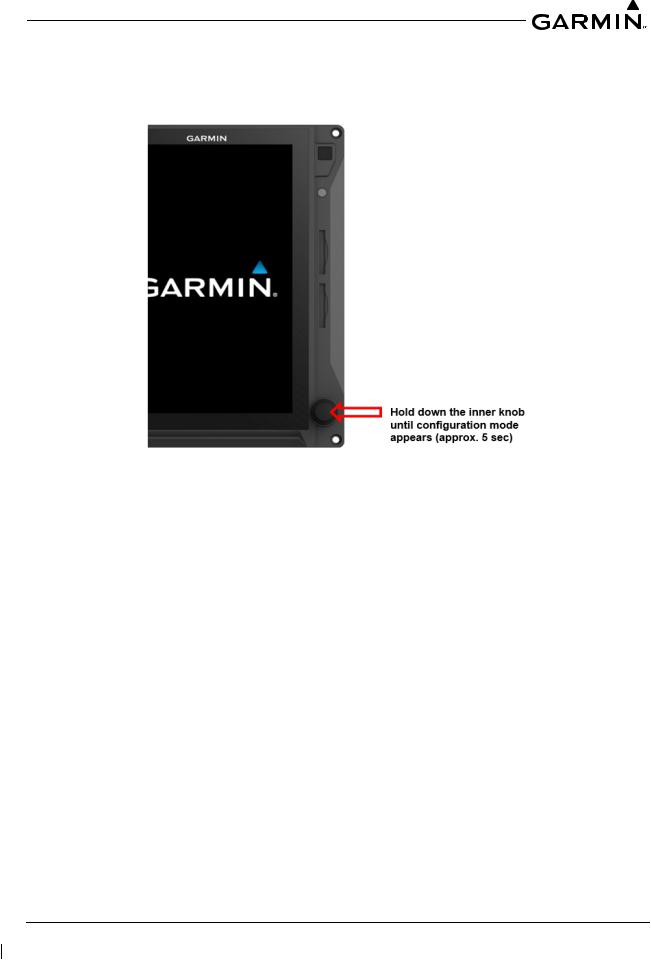
2.1.4Entering Configuration Mode
The Configuration mode of the GDU 700/1060 can be accessed by holding down the inner knob located at the bottom-right of the unit, as shown in Figure 2-1, upon initial power-up. The knob must be pressed until the splash screen shown in Figure 2-1 disappears and the configuration menu appears.
Figure 2-1 Entering the Configuration Mode on the GDU
2.1.5SD Card Location Options
The GDU 700/1060 has two SD card slots that can be used for various tasks. The following list describes what tasks can be performed from which SD card slot:
•Either slot
◦Installer unlock
◦Feature enablement
◦Screen shots (if a card is present in both slots, the screen shot will print to the top slot only)
◦Update databases
•Top/left slot only
◦Software updates
◦GSU/GRS log downloads
◦Flight log download
◦Save configuration to SD card
◦Save error log to SD card
◦Load configuration from SD card
•Bottom/right slot
◦Update databases (faster)
190-01717-B1 |
G500/G600 TXi Part 23 AML STC Maintenance Manual |
Rev. 4 |
Page 2-4 |

2.1.6Save/Load SD
The aircraft configuration settings can be saved to an SD card, as well as loaded from an SD card using the following procedures:
To save your aircraft configuration settings to an SD card:
1.Insert an SD card into the top/left slot of any GDU 700/1060 in the system.
2.Power on all GDUs in the G500/G600 TXi system in Configuration mode.
3.From the Home screen, select SD save.
4.Enter the name you would like the configuration saved as.
5.Select Enter.
To load your aircraft configuration settings from an SD card:
NOTE
An Installer Unlock Card is required to load configuration settings to an SD card.
NOTE
Loading the system configuration from an SD card will overwrite the current system configuration and is not reversible. It is recommended to always save your current configuration to the SD card first before loading a new configuration.
1.Insert an SD card into the top/left slot of any GDU 700/1060 in the system.
2.Power on all GDUs in the G500/G600 TXi system in Configuration mode.
3.Ensure you have set the GDU IDs, SYS ID Sources, and feature enablements before continuing.
4.From the Home screen, select SD load.
5.Select the Aircraft Configuration File you want to load.
6.Select the To GDU to which you want to load configuration settings.
NOTE
Information not contained in the selected Aircraft Configuration File will be grayed out and cannot be selected.
7.Select the check box next to the configuration to be loaded.
8.Select SD Load.
9.Verify the loaded configuration(s) is identical to those recorded in the aircraft’s permanent records.
10.Perform the Configuration Ground Check in Section 5.16.1. If any interfaces have a yellow triangle present on the system summary after loading a configuration from the SD card, verify the interface settings matchthe configuration settings storedwith the permanent aircraft records. If the settings do not match, the configuration must be corrected by a Garmin dealer.
190-01717-B1 |
G500/G600 TXi Part 23 AML STC Maintenance Manual |
Rev. 4 |
Page 2-5 |
2.1.7Electrical Load Information
Electrical load information for the G500/G600 TXi system LRUs is provided below. AppendixA of this document contains details specific to the load changes for the specific aircraft installation.
Table 2-2 G500/G600 TXi LRU Electrical Load
LRU |
14 Volt Current Draw |
28 Volt Current Draw |
|||
Typical |
Maximum |
Typical |
Maximum |
||
|
|||||
GDU 700( ) |
3.0 A |
6.0 A |
1.5 A |
3.0 A |
|
GDU 1060 |
5.0 A |
8.0 A |
2.5 A |
4.0 A |
|
GRS 79/GMU 44(B) |
480 mA |
958 mA |
240 mA |
479 mA |
|
GRS 77/GMU 44(B) |
600 mA |
1.0 A |
300 mA |
1.0 A |
|
GSU 75( )/GMU 44(B)/GTP 59 |
760 mA |
958 mA |
380 mA |
479 mA |
|
GDC 72/GTP 59 |
420 mA |
958 mA |
210 mA |
479 mA |
|
GDC 74( )/GTP 59 |
410 mA |
480 mA |
200 mA |
235 mA |
|
GAD 43 |
410 mA |
720 mA |
210 mA |
350 mA |
|
GAD 43e |
790 mA |
1.22 A |
390 mA |
590 mA |
|
GCU 485 |
120 mA |
357 mA |
64 mA |
179 mA |
|
GEA 110 |
0.30 A |
0.60 A |
0.15 A |
0.30 A |
|
GEA 71B Enhanced (-02) |
|
|
0.15 A |
0.54 A |
|
GEA 71B Enhanced (-05) |
|
|
0.27 A |
0.66 A |
|
190-01717-B1 |
G500/G600 TXi Part 23 AML STC Maintenance Manual |
Rev. 4 |
Page 2-6 |

2.2 LRU Description, Control, and Operation
2.2.1GDU 700P Display
The GDU 700P is a 7-inch LCD portrait-oriented panel mount control and display unit. The GDU 700P can be configured as a PFD, MFD, EIS, or MFD/EIS display. The GDU 700P cannot be configured for Turboprop EIS with the MFD/EIS configuration. Turboprop EIS is only available on the GDU 700P EIS configuration. The GDU 700P is available with or without an integratedADAHRS. The GDU 700P requires a compatible GPS/SBAS navigator for MFD and PFD functionality.
Figure 2-2 GDU 700P Display Configurations
(Clockwise from top left: MFD, PFD, Reciprocating EIS, Turboprop EIS, and MFD/EIS)
190-01717-B1 |
G500/G600 TXi Part 23 AML STC Maintenance Manual |
Rev. 4 |
Page 2-7 |

The GDU 700P has numerous features and controls, as shown in Figure 2-3. These features and controls are as follows:
•Power Button - Pressing and releasing the power button with the unit powered on will cause a dialog box to appear that allows the display to be powered off or, under certain circumstances, switched to a backup display layout. Pressing and holding the button for 5 seconds will power off the display with no further prompt
•Photocell - The photocell may be configured to be used by the display to automatically adjust the display backlighting in reference to ambient light conditions
•Top Card Slot -Acard slot in the display that accepts standard SD cards. See Section 2.1.5 for more information on SD card options
•Bottom Card Slot -Acard slot in the display that accepts standardSD cards. See Section 2.1.5 for more information on SD card options
•Dual Concentric Knobs - Control knobs that can be used to scroll and select through various options on the display. The outer knob is used to scroll through available screens on the PFD or MFD. Pressing the knob acts as an enter or selection of the currently highlighted information
PowerButton
Photocell
TopCardSlot
BottomCardSlot
Dual ConcentricKnob
|
Figure 2-3 GDU 700P Features and Controls |
190-01717-B1 |
G500/G600 TXi Part 23 AML STC Maintenance Manual |
Rev. 4 |
Page 2-8 |

2.2.2GDU 700L Display
The GDU 700Lis a 7-inch LCD landscape-oriented panel mount control and display unit. The GDU 700L can be configured as a PFD, EIS, or MFD/EIS split display. The GDU 700L cannot be configured for Turboprop EIS (only reciprocating engine EIS at this time). The GDU 700Lis available with or without an integratedADAHRS. The GDU 700L requires a compatible GPS/SBAS navigator for MFD and PFD functionality.
Figure 2-4 GDU 700L Display Configurations (Clockwise from top left: PFD, EIS, and MFD/EIS)
190-01717-B1 |
G500/G600 TXi Part 23 AML STC Maintenance Manual |
Rev. 4 |
Page 2-9 |

The GDU 700Lhas numerous features and controls, as shown in Figure 2-5. These features and controls are as follows:
•Power Button - Pressing and releasing the power button with the unit powered on will cause a dialog box to appear that allows the display to be powered off or, under certain circumstances, switched to a backup display layout. Pressing and holding the button for 5 seconds will power off the display with no further prompt
•Photocell - The photocell may be configured to be used by the display to automatically adjust the display backlighting in reference to ambient light conditions
•Left Card Slot - Acard slot in the display that accepts standard SD cards. See Section 2.1.5 for more information on SD card options
•Right Card Slot - Acard slot in the display that accepts standard SD cards. See Section 2.1.5 for more information on SD card options
•Dual Concentric Knobs - Control knobs that can be used to scroll and select through various options on the display. Pressing the knob acts as an enter or selection of the currently highlighted information
Power Key |
Photocell |
Left Card Slot |
Right Card Slot |
Dual Concentric Knob |
Figure 2-5 GDU 700L Features and Controls
190-01717-B1 |
G500/G600 TXi Part 23 AML STC Maintenance Manual |
Rev. 4 |
Page 2-10 |
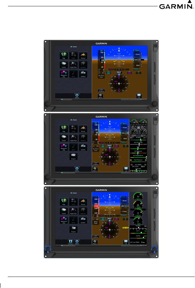
2.2.3GDU 1060 Display
The GDU 1060 is a 10.6-inchLCD panel mount control and display unit capable of displaying PFD and/or MFD data with optional EIS display. The GDU 1060 may be optionally equipped with an integrated ADAHRS or must be interfaced to an externalADC/AHRS LRU. Shown below is a combined PFD/MFD/ EIS display. The GDU 1060 requires interface with a compatible GPS/SBAS navigator.
Figure 2-6 GDU 1060 Display Configurations
(MFD/PFD and MFD/PFD/EIS with both Reciprocating EIS and Turboprop EIS shown)
190-01717-B1 |
G500/G600 TXi Part 23 AML STC Maintenance Manual |
Rev. 4 |
Page 2-11 |
Loading...