

k
Originalbetriebsanleitung
Universal-Kappsäge
t
Original Operating Instructions
Universal Crosscut Saw
p
Mode d’emploi d’origine
Scie tronçonneuse universelle
C
Istruzioni per l’uso originali
Troncatrice universale
U
Original-bruksanvisning
Universal-kapsåg
N
Originele handleiding
Universele afkortzaag
m
Manual de instrucciones original
Sierra oscilante universal
q
Alkuperäiskäyttöohje
Yleiskatkaisusaha
.
Originaalkasutusjuhend
Universaalne järkamissaag
z
Πρωτότυπες Οδηγίες χρήσης
Φαλτσοπρίονο γενικής χρήσης
Art.-Nr.: 43.007.90 I.-Nr.: 01019
RT-XM
305 U
Anleitung_RT_XM_305_U_SPK7:_ 22.10.2009 15:28 Uhr Seite 1

k Vor Inbetriebnahme Bedienungsanleitung und Sicherheitshinweise lesen und beachten.
t Read and follow the operating instructions and safety information before using the
equipment for the first time.
p Avant la mise en service, lire le mode d’emploi ainsi que les consignes de sécurité et les
respecter
C Prima della messa in esercizio leggete e osservate le istruzioni per l’uso e le avvertenze di
sicurezza.
U Läs igenom och beakta bruksanvisningen och säkerhetsanvisningarna före användning.
N Vóór ingebruikneming de handleiding en de veiligheidsvoorschriften lezen en in acht
nemen!
m Leer detenidamente las instrucciones de uso y las advertencias de seguridad antes de
poner en marcha el aparato
q Ennen käyttöönottoa tulee lukea käyttöohje ja turvallisuusmääräykset ja noudattaa niitä
. Enne kasutuselevõttu lugege kasutusjuhendit ja ohutuseeskirju ning järgige neid
z Πριν τη θέση σε λειτουργία διαβάστε την Οδηγία χρήσης και ακολουθήστε τις
Υποδείξεις ασφαλείας
2
Anleitung_RT_XM_305_U_SPK7:_ 22.10.2009 15:28 Uhr Seite 2
2 3
25
29
20
26
29
19
1
1
2
4
7
9
10
11
15
1617
10
9
23
21
8
22
12
14
33
34
3
13
32
31
31
24
35
27
30
18
5
6
28
3
Anleitung_RT_XM_305_U_SPK7:_ 22.10.2009 15:29 Uhr Seite 3
4 5
7
6
C
8
D
A
L
K
I
H
C
F
E
18
9
A
C
N
C
B
A
C
E
F
P
23
A
29
30
10
A
B
B
G
M
ON
9
10
Q
R
8
21
D
F
A
4
Anleitung_RT_XM_305_U_SPK7:_ 22.10.2009 15:29 Uhr Seite 4
9 10
11
1
12
1
13
14
L
L
H,G
E
E
C
C
B
A
K,I
C
B
A
B
L
C
A
B
A
C
5
Anleitung_RT_XM_305_U_SPK7:_ 22.10.2009 15:29 Uhr Seite 5
15 16
17
1
18
F
L
B
19
20
B
E
C
K,I
F
B
F
D
D
K,I
F
F
E
B
A
B
B
E
F
6
Anleitung_RT_XM_305_U_SPK7:_ 22.10.2009 15:29 Uhr Seite 6
22
23
24
25
31
37
22
21
F
E
38
B
C
Q
R
B
2.
1.
7
Anleitung_RT_XM_305_U_SPK7:_ 22.10.2009 15:29 Uhr Seite 7
26 27
28
7
29
38
O
30
31
17
7
b
17
20
19
37
O
19
20
a
8
Anleitung_RT_XM_305_U_SPK7:_ 22.10.2009 15:30 Uhr Seite 8
33
34
36
35
37
23
1.
2.
32
4039
34
35
23 33
9
Anleitung_RT_XM_305_U_SPK7:_ 22.10.2009 15:30 Uhr Seite 9

39
40
42
41
43
21
29
38
5
6
P
25
24
7
8
10
Anleitung_RT_XM_305_U_SPK7:_ 22.10.2009 15:30 Uhr Seite 10
4544
11
Anleitung_RT_XM_305_U_SPK7:_ 22.10.2009 15:30 Uhr Seite 11
Inhaltsverzeichnis: Seite
1. Sicherheitshinweise 13
2. Gerätebeschreibung 13
3. Lieferumfang 13
4. Bestimmungsgemäße Verwendung 14
5. Technische Daten 14
6. Vor Inbetriebnahme 15
7. Betrieb als Holz-/Kunststoffsäge 16
8. Betrieb als Metallsäge 18
9. Transport 18
10. Austausch der Netzanschlussleitung 18
11. Reinigung, Wartung und Ersatzteilbestellung 18
12. Entsorgung und Wiederverwertung 19
D
12
Anleitung_RT_XM_305_U_SPK7:_ 22.10.2009 15:30 Uhr Seite 12

Achtung!
Beim Benutzen von Geräten müssen einige
Sicherheitsvorkehrungen eingehalten werden, um
Verletzungen und Schäden zu verhindern. Lesen Sie
diese Bedienungsanleitung / Sicherheitshinweise
deshalb sorgfältig durch. Bewahren Sie diese gut auf,
damit Ihnen die Informationen jederzeit zur
Verfügung stehen. Falls Sie das Gerät an andere
Personen übergeben sollten, händigen Sie diese
Bedienungsanleitung / Sicherheitshinweise bitte mit
aus. Wir übernehmen keine Haftung für Unfälle oder
Schäden, die durch Nichtbeachten dieser Anleitung
und den Sicherheitshinweisen entstehen.
1. Sicherheitshinweise
Die entsprechenden Sicherheitshinweise finden Sie
im beiliegenden Heftchen!
WARNUNG
Lesen Sie alle Sicherheitshinweise und
Anweisungen. Versäumnisse bei der Einhaltung der
Sicherheitshinweise und Anweisungen können
elektrischen Schlag, Brand und/oder schwere
Verletzungen zur Folge haben.
Bewahren Sie alle Sicherheitshinweise und
Anweisungen für die Zukunft auf.
2. Gerätebeschreibung
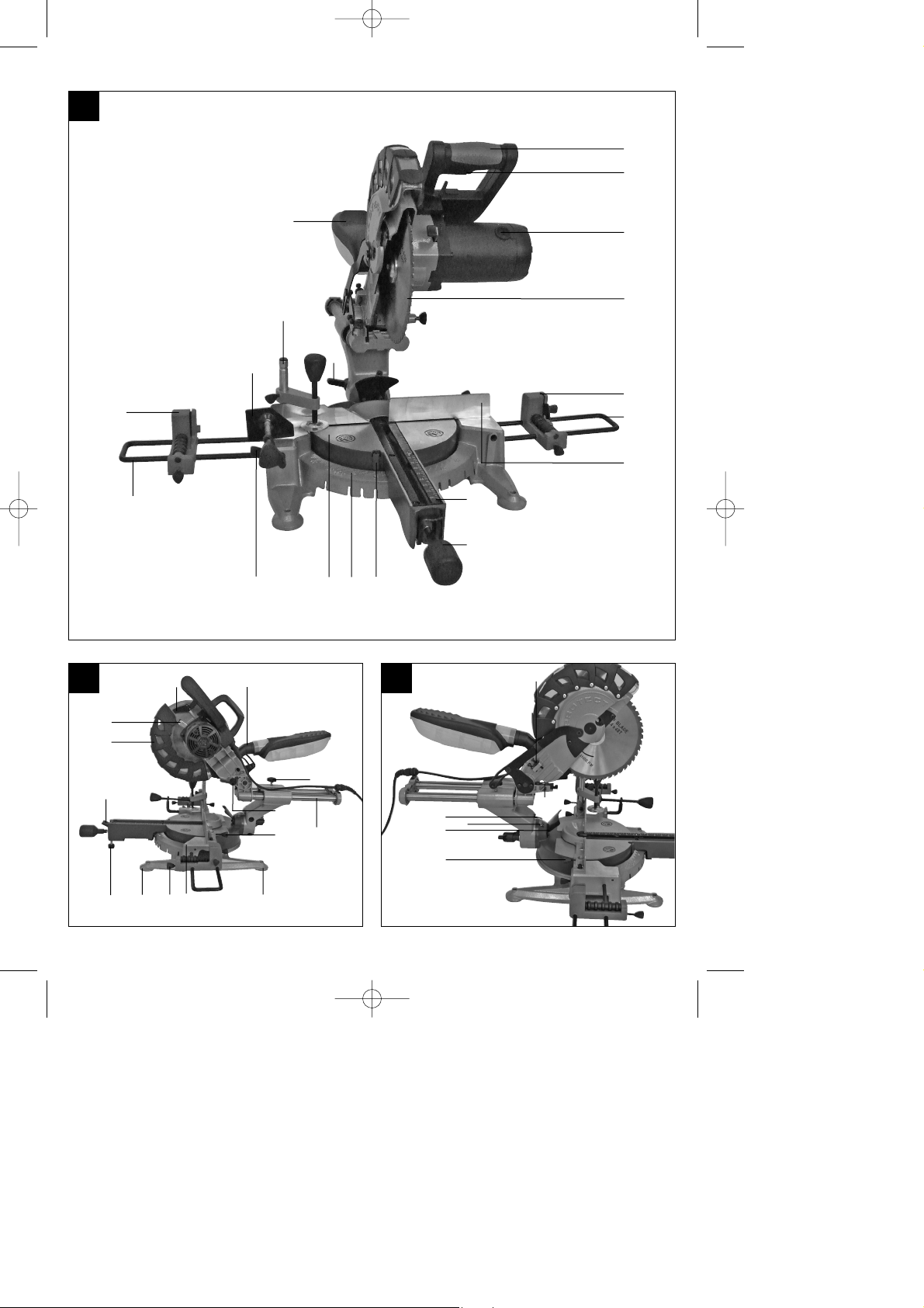
2.1 Zug-, Kapp- und Gehrungssäge (Bild 1-3)
1. Handgriff
2. Ein-/Ausschalter
3. Entriegelungshebel
4. Maschinenkopf
5. Sägewellensperre
6. Sägeblattschutz beweglich
7. Sägeblatt
8. Spannvorrichtung senkrecht
9. Rollauflage mit Endanschlag
10. Haltebügel für Rollauflage
11. Anschlagschiene
12. Tischeinlage mit Skala für Schnittlänge
13. Raststellungshebel
14. Feststellgriff
15. Zeiger
16. Skala
17. Drehtisch
18. feststehender Sägetisch
19. Skala
20. Zeiger
21. Spannvorrichtung waagrecht
22. Feststellschraube
23. Spänefangbox
24. Zugführung
25. Feststellschraube für Zugführung
26. Schutz
27. Sicherungsbolzen
28. Feststellschraube für waagrechte
Spannvorrichtung
29. Feststellschraube für senkrechte
Spannvorrichtung
30. Feststellschraube für Rollauflage
31. Standfuß mit Gummipuffer
32. Stützfuß
33. Absaugadapter
34. Rändelschraube für Schnitttiefenbegrenzung
35. Anschlag für Schnitttiefenbegrenzung
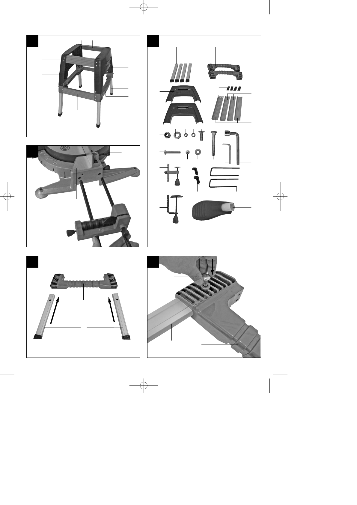
2.2 Untergestell (Bild 4)
A. Standfüße
B. Seitenteil
C. Zwischenstrebe
D. Eckversteifung
E. Untere Querstreben
F. Obere Querstreben
3. Lieferumfang (Bild 1, 5)
Zug-, Kapp und Gehrungssäge
Spannvorrichtung (8)
Rollauflage mit Endanschlag (9)
2 x Haltebügel für Rollauflage (10)
Spänefangbox (23)
4 x Standfüße (A)
2 x Seitenteil (B)
2 x Zwischenstrebe (C)
4 x Eckversteifung (D)
2 x Untere Querstreben (E)
2 x Obere Querstreben (F)
4 x Mutter (G)
4 x Beilagscheibe (H)
28 x Mutter (I)
28 x Beilagscheibe (K)
28 x Schraube (L)
4 x Schraube (N)
Inbusschlüssel (O)
Inbusschlüssel (P)
4 x Schraube (M)
4 x Beilagscheibe (Q)
4 x Hutmutter (R)
D
13
Anleitung_RT_XM_305_U_SPK7:_ 22.10.2009 15:30 Uhr Seite 13
4. Bestimmungsgemäße Verwendung
Die Universalsäge dient zum Kappen von Holz und
Kunststoff. Sie kann entsprechend der
Betriebsanleitung auch zum Sägen von hohlen
Metallprofilen mit rechteckigem Querschnitt
verwendet werden. Das Sägen von Metallprofilen
darf nur mit Kappschnitten erfolgen. Die Maschine ist
ausdrücklich nicht geeignet zum Sägen von Metall
mit einer Zugfestigkeit über 400 N/mm², gehärteten
Metallen, entzündlichen und reaktiven Metallen (wie
z.B. Magnesium und Magnesiumlegierungen),
Rundmaterial aller Art, Brennholz.
Die Maschine darf nur nach ihrer Bestimmung
verwendet werden. Jede weitere darüber hinausgehende Verwendung ist nicht bestimmungsgemäß.
Für daraus hervorgerufene Schäden oder
Verletzungen aller Art haftet der Benutzer/Bediener
und nicht der Hersteller.
Bitte beachten Sie, dass unsere Geräte
bestimmungsgemäß nicht für den gewerblichen,
handwerklichen oder industriellen Einsatz konstruiert
wurden. Wir übernehmen keine Gewährleistung,
wenn das Gerät in Gewerbe-, Handwerks- oder
Industriebetrieben sowie bei gleichzusetzenden
Tätigkeiten eingesetzt wird.
Es dürfen nur für die Maschine geeignete Sägeblätter
verwendet werden. Die Verwendung von
Trennscheiben aller Art ist untersagt.
Bestandteil der bestimmungsgemäßen Verwendung
ist auch die Beachtung der Sicherheitshinweise,
sowie die Montageanleitung und Betriebshinweise in
der Bedienungsanleitung.
Personen, die die Maschine bedienen und warten,
müssen mit dieser vertraut und über mögliche
Gefahren unterrichtet sein. Darüber hinaus sind die
geltenden Unfallverhütungsvorschriften genauestens
einzuhalten. Sonstige allgemeine Regeln in
arbeitsmedizinischen und sicherheitstechnischen
Bereichen sind zu beachten.
Veränderungen an der Maschine schließen eine
Haftung des Herstellers und daraus entstehende
Schäden gänzlich aus. Trotz bestimmungsgemäßer
Verwendung können bestimmte Restrisikofaktoren
nicht vollständig ausgeräumt werden. Bedingt durch
Konstruktion und Aufbau der Maschine können
folgende Punkte auftreten:
Berührung des Sägeblattes im nicht abgedeckten
Sägebereich.
Eingreifen in das laufende Sägeblatt
(Schnittverletzung)
Rückschlag von Werkstücken und
Werkstückteilen.
Sägeblattbrüche.
Herausschleudern von fehlerhaften
Hartmetallteilen des Sägeblattes.
Gehörschäden bei Nichtverwendung des nötigen
Gehörschutzes.
Gesundheitsschädliche Emissionen von Metall-
und Holzstäuben bei Verwendung in
geschlossenen Räumen.
Schnittverletzungen an Spänen und
Werkstücken.
Augenverletzungen durch Metallspäne.
5. Technische Daten
Wechselstrommotor: 230V ~ 50Hz
Leistung: 1800 W
Betriebsart: S1
Leerlaufdrehzahl n0: 2500 min
-1
Hartmetallsägeblatt: ø 250 x ø 30 x 2,2 mm
Anzahl der Zähne: 48
Schwenkbereich: -52° / 0°/ +60°
Gehrungsschnitt: 0° bis 45° nach links
Sägebreite bei 90°:
Holz: 305 x 75 mm
Metall: 105 x 75 mm
Sägebreite bei 45°:
Holz: 210 x 75 mm
Metall: 70 x 75 mm
Sägebreite bei 2 x 45° (Doppelgehrungsschnitt):
Holz: 210 x 40 mm
Metall: 70 x 40 mm
Gewicht: ca. 17,5 kg
Geräusch und Vibration
Die Geräusch- und Vibrationswerte wurden
entsprechend EN 13898 ermittelt.
Schalldruckpegel L
pA
93,7 dB(A)
Unsicherheit K
pA
2 dB
Schallleistungspegel L
WA
108,5 dB(A)
Unsicherheit K
WA
2 dB
Tragen Sie einen Gehörschutz.
Die Einwirkung von Lärm kann Gehörverlust
bewirken.
D
14
Anleitung_RT_XM_305_U_SPK7:_ 22.10.2009 15:30 Uhr Seite 14
”Die angegebenen Werte sind Emissionswerte und
müssen damit nicht zugleich auch sichere
Arbeitsplatzwerte darstellen. Obwohl es eine
Korrelation zwischen Emissions- und
Immissionspegeln gibt, kann daraus nicht
zuverlässig abgeleitet werden, ob zusätzliche
Vorsichtsmaßnahmen notwendig sind oder nicht.
Faktoren, welche den derzeitigen am Arbeitsplatz
vorhandenen Immissionspegel beeinflussen können,
beinhalten die Dauer der Einwirkungen, die Eigenart
des Arbeitsraumes, andere Geräuschquellen usw.,
z.B. die Anzahl der Maschinen und anderen
benachbarten Vorgängen. Die zuverlässigen
Arbeitsplatzwerte können ebenso von Land zu Land
variieren. Diese Information soll jedoch den
Anwender befähigen, eine bessere Abschätzung von
Gefährdung und Risiko vorzunehmen.”
Schwingungsgesamtwerte (Vektorsumme dreier
Richtungen) ermittelt entsprechend EN 61029.
Schwingungsemissionswert a
h
= 1,068 m/s
2
Beschränken Sie die Geräuschentwicklung und
Vibration auf ein Minimum!
Verwenden Sie nur einwandfreie Geräte.
Warten und reinigen Sie das Gerät regelmäßig.
Passen Sie Ihre Arbeitsweise dem Gerät an.
Überlasten Sie das Gerät nicht.
Lassen Sie das Gerät gegebenenfalls
überprüfen.
Schalten Sie das Gerät aus, wenn es nicht
benutzt wird.
Tragen Sie Handschuhe.
6. Vor Inbetriebnahme
6.1 Allgemein
Die Maschine muss standsicher aufgestellt
werden, d.h. auf einer Werkbank, dem
serienmäßigen Untergestell o. ä. festschrauben.
Vor Inbetriebnahme müssen alle Abdeckungen
und Sicherheitsvorrichtungen ordnungsgemäß
montiert sein.
Das Sägeblatt muss frei laufen können.
Bei bereits bearbeitetem Holz auf Fremdkörper
wie z.B. Nägel oder Schrauben usw. achten.
Bevor Sie den Ein- / Ausschalter betätigen,
vergewissern Sie sich, ob das Sägeblatt richtig
montiert ist und bewegliche Teile leichtgängig
sind.
Überzeugen Sie sich vor dem Anschließen der
Maschine, dass die Daten auf dem Typenschild
mit den Netzdaten übereinstimmen.
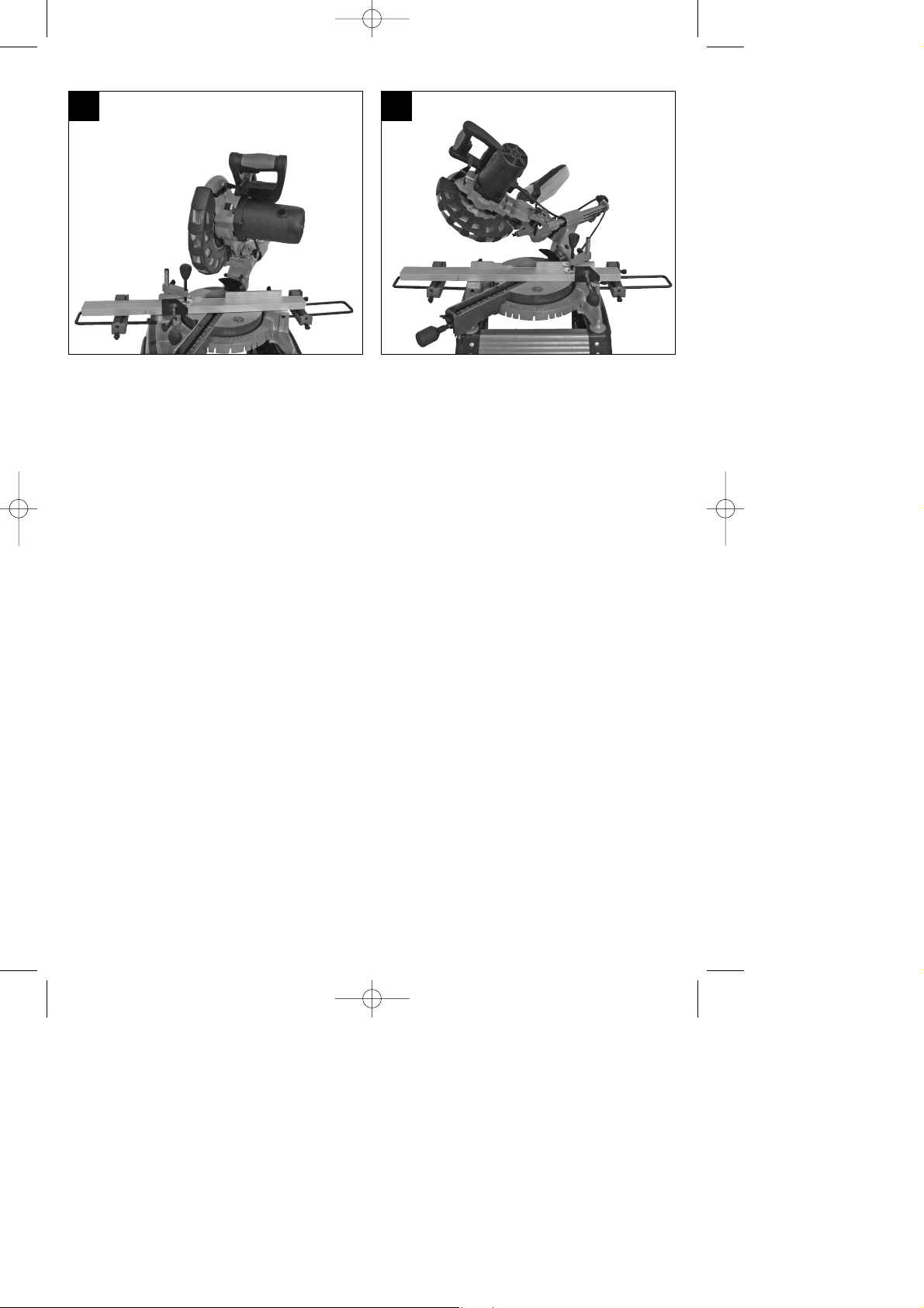
6.2 Säge montieren (Bild 1-3; 6)
Zum Verstellen des Drehtisches (17) den
Feststellgriff (14) ca. 2 Umdrehungen lockern um
den Drehtisch (17) zu entriegeln.
Raststellungshebel (13) drücken, Drehtisch (17)
und Zeiger (15) auf das gewünschte Winkelmaß
der Skala (16) drehen und mit dem Feststellgriff
(14) fixieren. Die Säge besitzt Raststellungen bei
den Positionen -45°, -30°, -22,5°, -15°, 0°, 15°,
22,5°, 30°, 45° und 60°, an denen man den
Raststellungshebel einrasten lassen kann.
Durch leichtes Drücken des Maschinenkopfes (4)
nach unten und gleichzeitiges Herausziehen des
Sicherungsbolzens (27) aus der Motorhalterung,
wird die Säge aus der unteren Stellung
entriegelt. Drehen Sie den Sicherungsbolzen
(27) um 90° bevor sie ihn loslassen, damit die
Säge entriegelt bleibt.
Maschinenkopf (4) nach oben schwenken, bis
der Entriegelungshebel (3) einrastet.
Die Vorrichtungen (8, 21) können sowohl links
als auch rechts am feststehenden Sägetisch (18)
montiert werden.
Feststellschrauben für Rollauflage (30) lösen.
Die Rollauflage mit Endanschlag (9) über einen
der Haltebügel für Rollauflage (10) führen und
diese am feststehenden Sägetisch (18)
montieren, entsprechende Feststellschraube (30)
anziehen (Bild 6).
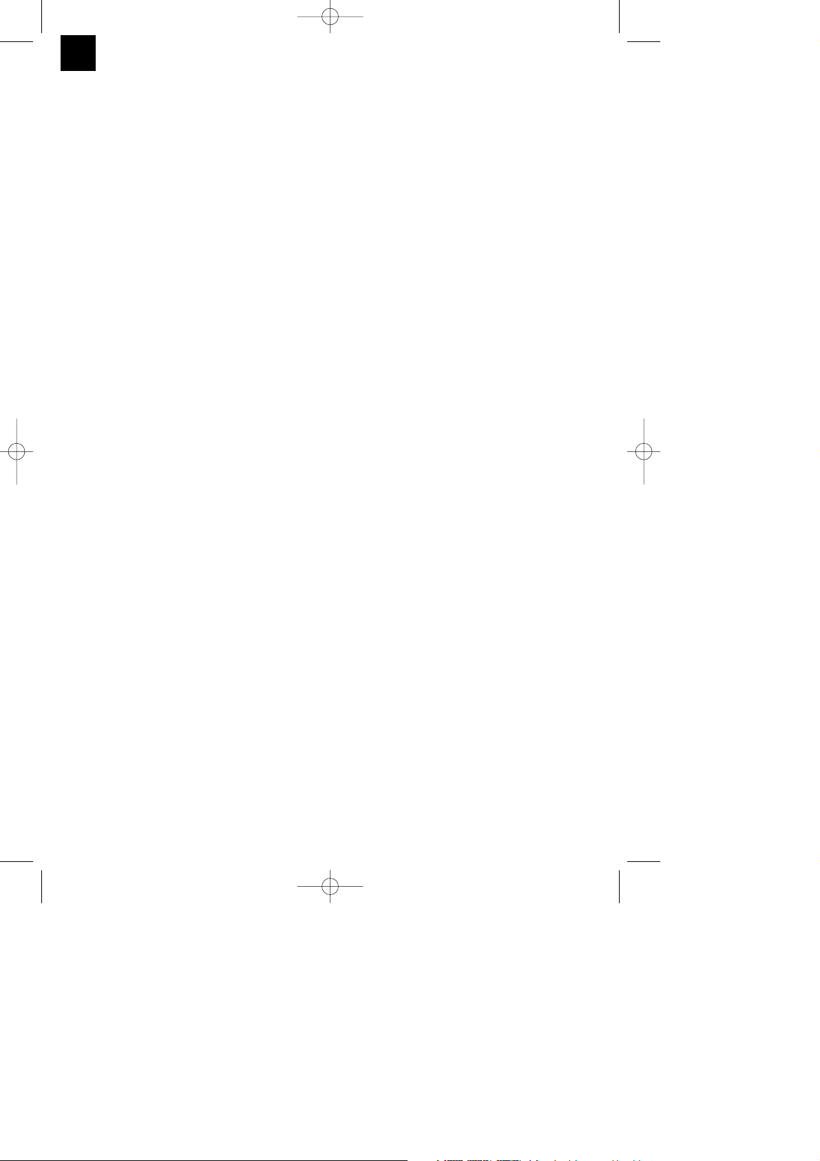
Den zweiten Haltebügel für Rollauflage (10) auf
der gegenüberliegenden Seite der Säge
montieren und mit der entsprechenden
Feststellschraube (30) sichern.
Der Maschinenkopf (4) kann durch lösen der
Feststellschraube (22), nach links auf max. 45°
geneigt werden.
Wird die Säge ohne Untergestell verwendet, so
dient der Stützfuß (32) dazu, dass die Säge im
Betrieb nicht nach vorne kippen kann. Drehen
Sie dazu den Stützfuß (32) heraus, bis er die
Stellfläche der Säge berührt.
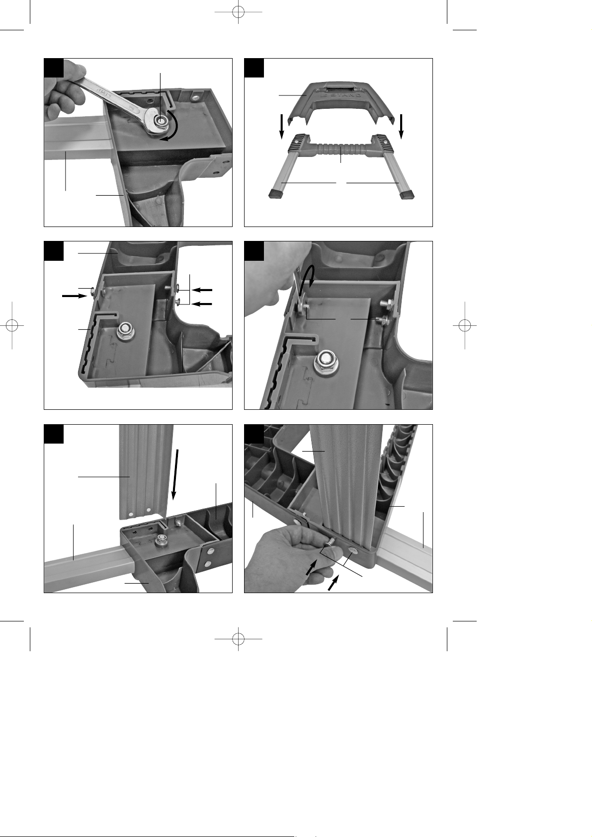
6.3 Untergestell montieren und Säge am
Untergestell verschrauben (Bild 4-24)
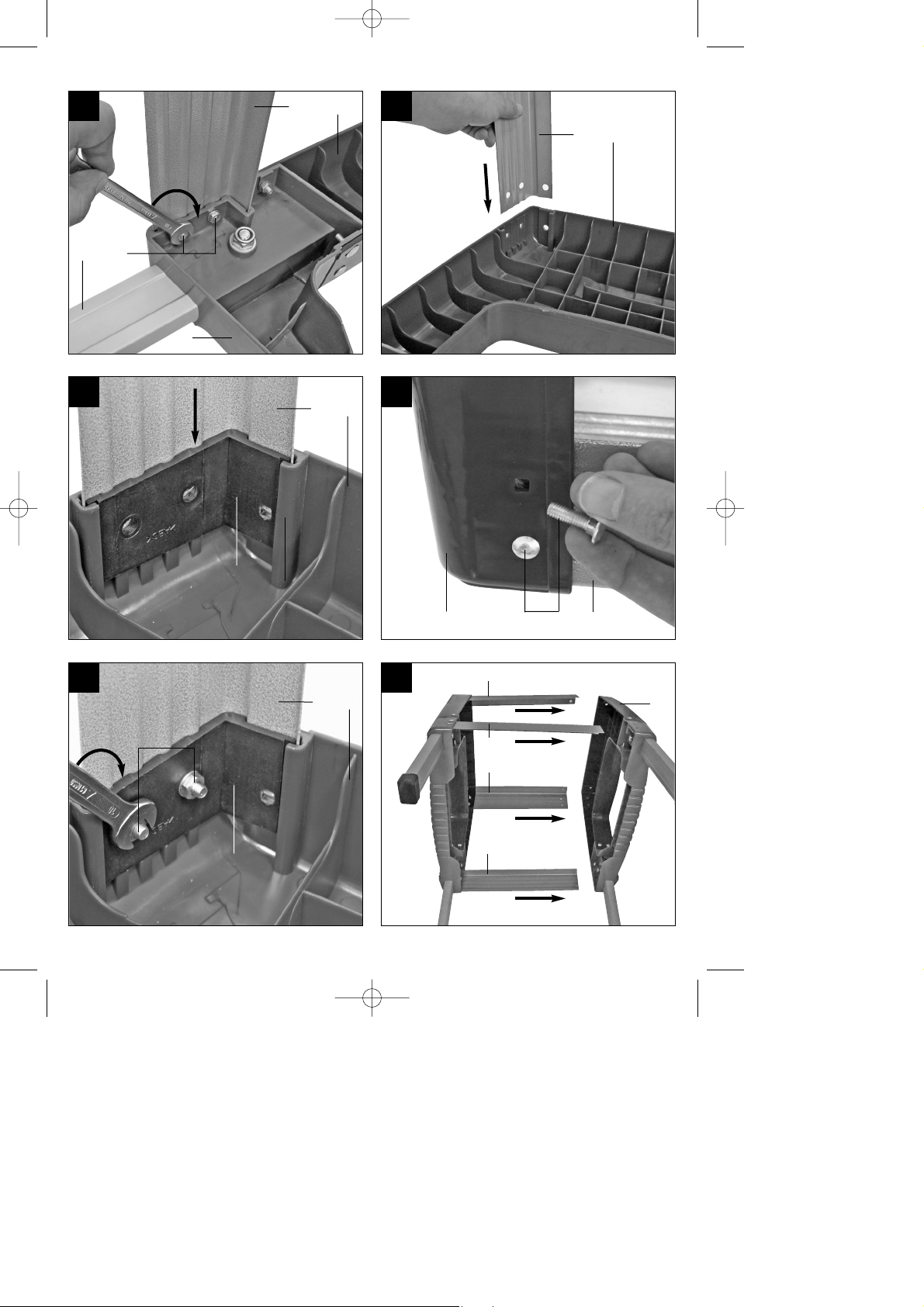
1. Die Standfüße (A), wie in Bild 7 dargestellt, von
unten in die Zwischenstreben (C) stecken.
Beachten, dass die Gummifüße an den
Standfüßen (A) so ausgerichtet sind, dass die
Auflageflächen gerade sind.
2. Standfüße (A) mit den Schrauben (N), den
Beilagscheiben (H) und Muttern (G), wie in den
Bildern 8 - 9 dargestellt, an den Zwischenstreben
(C) verschrauben.
3. Seitenteile (B) von oben über die
Zwischenstreben (C) führen (Bild 10).
4. Seitenteile (B) an jeder Verbindungsstelle mit 3
D
15
Anleitung_RT_XM_305_U_SPK7:_ 22.10.2009 15:30 Uhr Seite 15

Schrauben (L), Beilagscheiben (K) und Muttern
(I) mit den Zwischenstreben (C) verschrauben
(Bild 11 - 12).
5. Die beiden unteren Querstreben (E) bis zum
Anschlag in die entsprechenden Aussparungen
einer der Zwischenstreben (C) stecken (Bild 13).
Untere Querstreben (E) mit jeweils 2 Schrauben
(L), Beilagscheiben (K) und Muttern (I), wie in
Bild 14 – 15 dargestellt, an der Zwischenstrebe
(C) verschrauben.
6. An der selben Untergestellhälfte die beiden
oberen Querstreben (F) bis zum Anschlag in die
entsprechenden Aussparungen des Seitenteils
(B) führen (Bild 16). Jeweils eine Eckversteifung
(D) mit in die Aussparung des Seitenteils (B)
stecken. Beachten Sie, dass die
Eckversteifungen (D) jeweils nur an einer Seite
des Untergestells passen, dies ist der Fall wenn
die Löcher in Seitenteil (B), oberen Querstreben
(F) und Eckversteifungen (D) deckungsgleich
sind (Bild 17).
7. Nun obere Querstreben (F), Eckversteifungen
(D), Seitenteil (B), wie in Bild 18 – 19 dargestellt,
mit jeweils 2 Schrauben (L), Beilagscheiben (K)
und Muttern (I) verschrauben.
8. Die beiden Untergestellhälften so zusammen
stecken, dass die unteren und oberen
Querstreben (E, F) in den entsprechenden
Aussparungen an Seitenteil (B) und
Zwischenstrebe (C) sitzen (Bild 20).
9. Untere Querstreben (E) wie unter 5. beschrieben
an der zweiten Untergestellhälfte verschrauben
(Bild 21/1.).
10. Obere Querstreben (F) wie unter 6. beschrieben
an der zweiten Untergestellhälfte verschrauben
(Bild 21/2.).
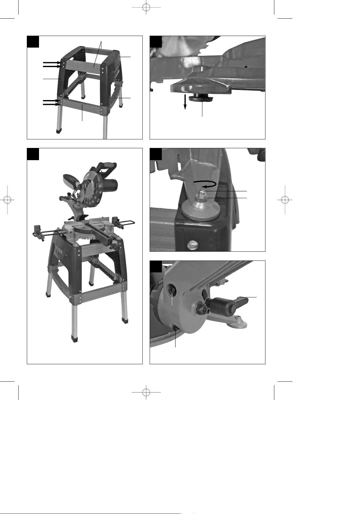
11. Die vier Gummipuffer (32) an der Unterseite der
Säge abziehen (Bild 22).
12. Die Säge so auf das Untergestell stellen, dass
die Löcher, in denen sich die Gummipuffer (32)
befunden haben, deckungsgleich mit den 4
Löchern an der Oberseite der Sägeaufnahmen
(J) sind. Nun die 4 Schrauben (M) von oben
durch die Sägefüße stecken und Säge mit dem
Untergestell verschrauben (Bild 23 – 24).
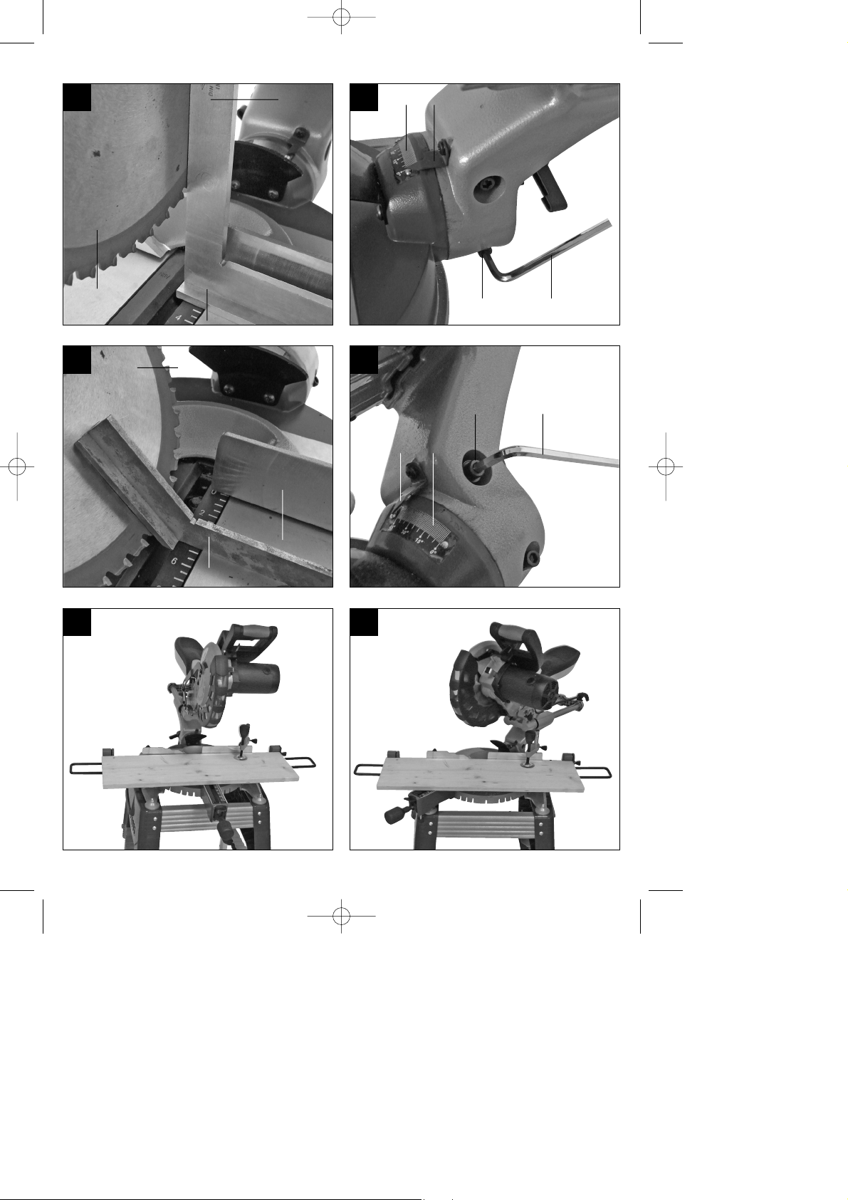
6.4 Feinjustierung des Anschlags für
Kappschnitt 90° (Bild 1, 25-27)
Den Drehtisch (17) auf 0° Stellung fixieren.
Feststellschraube (22) lockern und mit dem
Handgriff (1) den Maschinenkopf (4) ganz nach
rechts neigen.
90° Anschlagwinkel (a) zwischen Sägeblatt (7)
und Drehtisch (17) anlegen.
Justierschraube (38) soweit verstellen, bis der
Winkel zwischen Sägeblatt (7) und Drehtisch
(17) 90° beträgt.
Überprüfen Sie abschließend die Position des
Zeigers (20) an der Skala (19) Falls erforderlich,
Zeiger (20) mit Kreuzschlitzschraubendreher
lösen, auf 0°-Position der Skala (19) setzen und
Halteschraube wieder festziehen.
Anschlagwinkel nicht im Lieferumfang
enthalten.
6.5 Feinjustierung des Anschlags für
Gehrungsschnitt 45° (Bild 1, 25, 28-29)
Den Drehtisch (17) auf 0° Stellung fixieren.
Feststellschraube (22) lösen und mit dem
Handgriff (1) den Maschinenkopf (4) ganz nach
links, auf 45° neigen.
45°-Anschlagwinkel (b) zwischen Sägeblatt (7)
und Drehtisch (17) anlegen.
Justierschraube (37) soweit verstellen, dass der
Winkel zwischen Sägeblatt (7) und Drehtisch
(17) genau 45° beträgt.
Anschlagwinkel nicht im Lieferumfang
enthalten.
7. Betrieb als Holz-/Kunststoffsäge
7.1 Kappschnitt 90° und Drehtisch 0°
(Bild 1–3, 30)
Bei Schnittbreiten bis ca. 100 mm kann die
Zugfunktion der Säge mit der Feststellschraube für
Zugführung (25) in der hinteren Position fixiert
werden. Sollte die Schnittbreite über 100 mm liegen,
muss darauf geachtet werden, dass die
Feststellschraube für Zugführung (25) locker und der
Maschinenkopf (4) beweglich ist.
Maschinenkopf (4) in die obere Position bringen.
Maschinenkopf (4) am Handgriff (1) nach hinten
schieben und gegebenenfalls in dieser Position
fixieren. (je nach Schnittbreite)
Legen Sie das zu schneidende Holz an die
Anschlagschiene (11) und auf den Drehtisch
(17).
Das Material mit der Spannvorrichtung (8) auf
dem feststehenden Sägetisch (18) feststellen,
um ein Verschieben während des
Schneidvorgangs zu verhindern.
Entriegelungshebel (3) drücken um den
Maschinenkopf (4) freizugeben.
Ein-/ Ausschalter (2) drücken, um den Motor
einzuschalten.
Bei fixierter Zugführung (24): Maschinenkopf (4)
mit dem Handgriff (1) gleichmäßig und mit
leichtem Druck nach unten bewegen, bis das
Sägeblatt (7) das Werkstück durchschnitten hat.
Bei nicht fixierter Zugführung (24):
Maschinenkopf (4) nach ganz nach vorne ziehen
16
D
Anleitung_RT_XM_305_U_SPK7:_ 22.10.2009 15:30 Uhr Seite 16

und dann mit dem Handgriff (1) gleichmäßig
und mit leichtem Druck ganz nach unten
absenken. Nun Maschinenkopf (4) langsam und
gleichmäßig ganz nach hinten schieben, bis das
Sägeblatt (7) das Werkstück vollständig
durchschnitten hat.
Nach Beendigung des Sägevorgangs
Maschinenkopf (4)wieder in die obere
Ruhestellung bringen und Ein-/ Ausschalter (2)
loslassen.
Achtung! Durch die Rückholfeder schlägt die
Maschine automatisch nach oben, d.h. Handgriff (1)
nach Schnittende nicht loslassen, sondern
Maschinenkopf (4) langsam und unter leichtem
Gegendruck nach oben bewegen.
7.2 Kappschnitt 90° und Drehtisch -52°...+60°
(Bild 1-3, 31)
Mit der Kappsäge können Kappschnitte von 0° - 52°
nach links und 0° - 60° nach rechts zur
Anschlagschiene ausgeführt werden.
Den Drehtisch (17) durch Lockern des
Feststellgriffes (14) lösen.
Raststellungshebel (13) drücken, Drehtisch (17)
und Zeiger (15) auf das gewünschte Winkelmaß
der Skala (16) drehen und mit dem Feststellgriff
(14) fixieren. Die Säge besitzt Raststellungen bei
den Positionen -45°, -30°, -22,5°, -15°, 0°, 15°,
22,5°, 30°, 45° und 60°, an denen man den
Raststellungshebel einrasten lassen kann.
Den Feststellgriff (14) wieder festziehen, um den
Drehtisch (17) zu fixieren.
Schnitt wie unter Punkt 7.1 beschrieben
ausführen.
7.3 Gehrungsschnitt 0°- 45° und Drehtisch 0°
(Bild 1–3, 32)
Mit der Kappsäge können Gehrungsschnitte nach
links von 0°- 45° zur Arbeitsfläche ausgeführt
werden.
Spannvorrichtung (8) gegebenenfalls
demontieren oder auf der gegenüberliegenden
Seite des feststehenden Sägetisches (18)
montieren.
Maschinenkopf (4) in die obere Stellung bringen.
Den Drehtisch (17) auf 0° Stellung fixieren.
Die Feststellschraube (22) lösen und mit dem
Handgriff (1) den Maschinenkopf (4) nach links
neigen, bis der Zeiger (20) auf das gewünschte
Maß auf der Skala (19) zeigt.
Feststellschraube (22) wieder festziehen und
Schnitt wie unter Punkt 7.1 beschrieben
durchführen.
7.4 Gehrungsschnitt 0°- 45° und Drehtisch 0°- 45°
(Bild 1–3, 33)
Mit der Kappsäge können Gehrungsschnitte nach
links von 0°- 45° zur Arbeitsfläche und gleichzeitig
0°- 52° nach links bzw. 0° - 60° nach rechts zur
Anschlagschiene ausgeführt werden
(Doppelgehrungsschnitt).
Spannvorrichtung (8) gegebenenfalls demon-
tieren oder auf der gegenüberliegenden Seite
des feststehenden Sägetisches (18) montieren.
Maschinenkopf (4) in die obere Stellung bringen.
Den Drehtisch (17) durch Lockern des
Feststellgriffes (14) lösen.
Mit dem Handgriff (1) den Drehtisch (17) auf den
gewünschten Winkel einstellen (siehe hierzu
auch Punkt 7.2).
Den Feststellgriff (14) wieder festziehen, um den
Drehtisch zu fixieren.
Die Feststellschraube (22) lösen und mit dem
Handgriff (1) den Maschinenkopf (4) nach links,
auf das gewünschte Winkelmaß neigen (siehe
hierzu auch Punkt 7.3).
Feststellschraube (22) wieder festziehen.
Schnitt wie unter Punkt 7.1 beschrieben
ausführen.
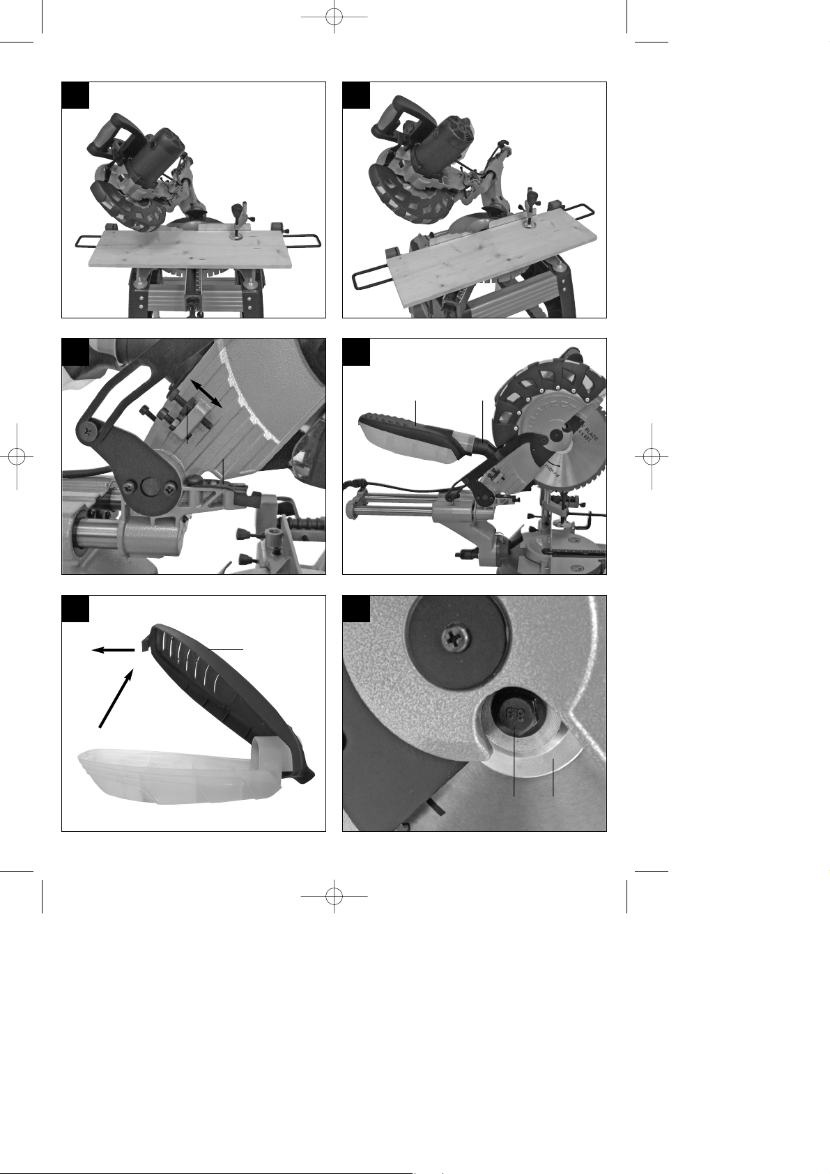
7.5 Schnitttiefenbegrenzung (Bild 34)
Mittels der Schraube (34) kann die Schnitttiefe
stufenlos eingestellt werden. Lösen Sie hierzu
die Rändelmutter an der Schraube (34) und
klappen Sie den Anschlag für Schnitttiefenbegrenzung (35) nach außen. Stellen Sie die
gewünschte Schnitttiefe durch Eindrehen oder
Herausdrehen der Schraube (34) ein und ziehen
Sie die Rändelmutter an der Schraube (34)
anschließend wieder fest.
Überprüfen Sie die Einstellung anhand eines
Probeschnittes.
7.6 Spänefangbox (Bild 35–36/Pos. 23)
Die Säge ist mit einer Spänefangbox (23) für Späne
ausgestattet. Die Spänefangbox (23) kann auf den
Absaugadapter (33) aufgesteckt werden.
Zum Entleeren der Spänefangbox (23) diese wie in
Bild 36 gezeigt aufklappen und vorsichtig ausklopfen.
Am Absaugadapter (33) kann auch eine geeignete
Staubabsaug-Vorrichtung angeschlossen werden.
7.7 Austausch des Sägeblatts (Bild 1, 37-40)
Netzstecker ziehen!
Den Maschinenkopf (4) nach oben schwenken
und durch den Sicherungsbolzen (27) in dieser
Position arretieren.
Entriegelungshebel (3) drücken und
17
D
Anleitung_RT_XM_305_U_SPK7:_ 22.10.2009 15:30 Uhr Seite 17

D
18
Sägeblattschutz (6) so weit nach oben klappen,
dass die Aussparung im Sägeblattschutz (6)
über der Flanschschraube (39) ist.
Mit einer Hand drücken Sie die
Sägewellensperre (5) mit der anderen Hand
setzen Sie den Schlüssel (P) auf die
Flanschschraube (39).
Drücken Sie fest auf die Sägewellensperre (5)
und drehen Sie die Flanschschraube (39)
langsam im Uhrzeigersinn. Nach max. einer
Umdrehung rastet die Sägewellensperre (5) ein.
Jetzt mit etwas mehr Kraftaufwand
Flanschschraube (39) im Uhrzeigersinn lösen.
Drehen Sie die Flanschschraube (39) ganz her-
aus und nehmen Sie den Außenflansch (40) ab.
Das Sägeblatt (7) vom Innenflansch abnehmen
und nach unten herausziehen.
Flanschschraube (39), Außenflansch (40) und
Innenflansch sorgfältig reinigen.
Das neue Sägeblatt (7) in umgekehrter
Reihenfolge wieder einsetzen und festziehen.
Achtung! Die Schnittschräge der Zähne d.h. die
Drehrichtung des Sägeblattes (7), muss mit der
Richtung des Pfeils auf dem Gehäuse
übereinstimmen.
Bevor Sie mit der Säge weiter arbeiten, ist die
Funktionsfähigkeit der Schutzeinrichtungen zu
prüfen.
Achtung! Nach jedem Sägeblattwechsel prüfen,
ob das Sägeblatt in senkrechter Stellung sowie
auf 45° gekippt, frei in der Tischeinlage (12)
läuft.
Achtung! Das Wechseln und Ausrichten des
Sägeblattes (7) muss ordnungsgemäß
ausgeführt werden.
8. Betrieb als Metallsäge
Achtung! Tragen sie Handschuhe (Schnittgefahr)
und eine geeignete Schutzbrille.
Es können Kappschnitte mit und ohne Gehrung
in den bei 7.) angegebenen Winkelbereichen
durchgeführt werden. Für Metall sind wegen der
Rückschlaggefahr ausschließlich Kappschnitte
möglich. Dazu muss die Zugführung (24) mit der
Feststellschraube fixiert werden.
Kehren sie vor der Benutzung Metallspäne von
der Maschine, um Verletzungen zu vermeiden.
Spannen Sie das Werkstück immer mit
senkrechter Spannvorrichtung (8) und
waagrechter Spannvorrichtung (21).
Drücken Sie den Ein-/Ausschalter (2). Lassen
Sie das Sägeblatt vor dem Schnitt auf volle
Drehzahl laufen.
Den Entriegelungshebel (3) drücken. Bei fixierter
Zugführung (24) den Maschinenkopf (4) mit dem
Handgriff (1) gleichmäßig, zügig und mit leichtem
Druck nach unten bewegen, bis das Werkstück
durchschnitten ist
Nach Beendigung des Sägevorganges
Maschinenkopf (4) wieder in die obere
Ruhestellung bringen und Ein-/Ausschalter (2)
loslassen.
Vor dem Entnehmen des Werkstücks das
Sägeblatt auslaufen lassen
Achtung: Durch die Rückholfeder schlägt die
Maschine automatisch nach oben, d.h. Handgriff
(1) nach Schnittende nicht loslassen, sondern
Maschinenkopf (4) langsam und unter leichtem
Gegendruck nach oben bewegen.
9. Transport (Abb. 1-3)
Feststellgriff (14) festziehen, um den Drehtisch
(17) zu verriegeln
Entriegelungshebel (3) betätigen, Maschinenkopf
(4) nach unten drücken und mit
Sicherungsbolzen (27) arretieren. Die Säge ist
nun in der unteren Stellung verriegelt.
Zugfunktion der Säge mit der Feststellschraube
für Zugführung (25) in der hinteren Position
fixieren.
Tragen Sie die Maschine am feststehenden
Sägetisch (18) oder, falls die Säge auf dem
Untergestell montiert ist, an den entsprechenden
Griffmulden des Untergestells.
Um die Maschine erneut aufzubauen, gehen Sie
nach Punkt 6.2 vor.
10. Austausch der
Netzanschlussleitung
Wenn die Netzanschlussleitung dieses Gerätes
beschädigt wird, muss sie durch den Hersteller oder
seinen Kundendienst oder eine ähnlich qualifizierte
Person ersetzt werden, um Gefährdungen zu
vermeiden.
Anleitung_RT_XM_305_U_SPK7:_ 22.10.2009 15:30 Uhr Seite 18

D
19
11. Reinigung, Wartung und
Ersatzteilbestellung
Ziehen Sie vor allen Reinigungsarbeiten den
Netzstecker.
11.1 Reinigung
Halten Sie Schutzvorrichtungen, Luftschlitze und
Motorengehäuse so staub- und schmutzfrei wie
möglich. Reiben Sie das Gerät mit einem
sauberen Tuch ab oder blasen Sie es mit
Druckluft bei niedrigem Druck aus.
Wir empfehlen, dass Sie das Gerät direkt nach
jeder Benutzung reinigen.
Reinigen Sie das Gerät regelmäßig mit einem
feuchten Tuch und etwas Schmierseife.
Verwenden Sie keine Reinigungs- oder
Lösungsmittel; diese könnten die Kunststoffteile
des Gerätes angreifen. Achten Sie darauf, dass
kein Wasser in das Geräteinnere gelangen kann.
11.2 Kohlebürsten
Bei übermäßiger Funkenbildung lassen Sie die
Kohlebürsten durch eine Elektrofachkraft überprüfen.
Achtung! Die Kohlebürsten dürfen nur von einer
Elektrofachkraft ausgewechselt werden.
11.3 Wartung
Im Geräteinneren befinden sich keine weiteren zu
wartenden Teile.
11.4 Ersatzteilbestellung:
Bei der Ersatzteilbestellung sollten folgende
Angaben gemacht werden;
Typ des Gerätes
Artikelnummer des Gerätes
Ident-Nummer des Gerätes
Ersatzteilnummer des erforderlichen Ersatzteils
Aktuelle Preise und Infos finden Sie unter
www.isc-gmbh.info
12. Entsorgung und Wiederverwertung
Das Gerät befindet sich in einer Verpackung um
Transportschäden zu verhindern. Diese Verpackung
ist Rohstoff und ist somit wieder verwendbar oder
kann dem Rohstoffkreislauf zurückgeführt werden.
Das Gerät und dessen Zubehör bestehen aus
verschiedenen Materialien, wie z.B. Metall und
Kunststoffe. Führen Sie defekte Bauteile der
Sondermüllentsorgung zu. Fragen Sie im
Fachgeschäft oder in der Gemeindeverwaltung nach!
Anleitung_RT_XM_305_U_SPK7:_ 22.10.2009 15:30 Uhr Seite 19

GB
20
Table of contents: Page
1. Safety Information 21
2. Layout 21
3. Items supplied 21
4. Intended use 22
5. Technical data 22
6. Before starting the equipment 23
7. Operation as wood/plastics saw 24
8. Operation as metal saw 26
9. Transport 26
10. Replacing the power cable 26
11. Cleaning, maintenance and ordering of spare parts 26
12. Disposal and recycling 26
Anleitung_RT_XM_305_U_SPK7:_ 22.10.2009 15:30 Uhr Seite 20

GB
21
Important.
When using the equipment, a few safety precautions
must be observed to avoid injuries and damage.
Please read the complete operating instructions and
safety information with due care. Keep this manual in
a safe place so that the information is available at all
times. If you give the equipment to any other person,
hand over these operating instructions and the safety
information as well. We cannot accept any liability for
damage or accidents which arise due to a failure to
follow these instructions and the safety information.
1. Safety Information
Please refer to the booklet included in delivery for the
safety information.
CAUTION
Read all the safety information and instructions.
Any errors made in following the safety regulations
and instructions may result in an electric shock, fire
and/or serious injury.
Keep all safety regulations and instructions in a
safe place for future use.
2. Layout
2.1 Drag, crosscut and miter saw (Fig. 1-3)
1. Handle
2. ON/OFF switch
3. Release lever
4. Machine head
5. Saw shaft lock
6. Movable blade guard
7. Saw blade
8. Vertical clamping device
9. Roll base with limit stop
10. Holding bar for the roll base
11. Stop rail
12. Table insert with cutting depth scale
13. Latched position lever
14. Locking grip
15. Pointer
16. Scale
17. Turntable
18. Fixed saw table
19. Scale
20. Pointer
21. Horizontal clamping device
22. Locking screw
23. Chip box
24. Drag guide
25. Locking screw for drag guide
26. Guard
27. Fastening bolt
28. Locking screw for the horizontal clamping device
29. Locking screw for the vertical clamping device
30. Locking screw for the roll base
31. Foot with rubber stopper
32. Foot
33. Extractor adapter
34. Knurled screw for cutting depth limiter
35. Stop for cutting depth limiter
2.2 Base frame (Fig. 4)
A. Feet
B. Side part
C. Intermediate strut
D. Corner bracing
E. Bottom cross strut
F. Top cross strut
3. Items supplied (Fig. 1, 5)
Drag, crosscut and miter Saw
Clamping device (8)
Roll base with limit stop (9)
2 x Holding bar for the roll base (10)
Chip box (23)
4 x Foot (A)
2 x Side part (B)
2 x Intermediate strut (C)
4 x Corner bracing (D)
2 x Bottom cross strut (E)
2 x Top cross strut (F)
4 x Nut (G)
4 x Washers (H)
28 x Nut (I)
28 x Washer (K)
28 x Screw (L)
4 x Screw (N)
Allen key (O)
Allen key (P)
4 x Screw (M)
4 x Washer (Q)
4 x Cap nut (R)
Anleitung_RT_XM_305_U_SPK7:_ 22.10.2009 15:30 Uhr Seite 21
4. Intended use
The universal saw is designed for cross-cutting wood
and plastic. In accordance with the operating
instructions the equipment can also be used to saw
hollow metal profiles with a rectangular cross-section.
Sawing metal profiles may only be carried out with
crosscuts. The equipment is expressly not permitted
to saw metal with a tensile strength of more than 400
N/mm², hardened metal, combustible and reactive
metals (such as magnesium and magnesium alloys),
all kinds of round materials and firewood.
The equipment is to be used only for its prescribed
purpose. Any other use is deemed to be a case of
misuse.
The user / operator and not the manufacturer will be
liable for any damage or injuries of any kind caused
as a result of this.
Please note that our equipment has not been
designed for use in commercial, trade or industrial
applications. Our warranty will be voided if the
equipment is used in commercial, trade or industrial
businesses or for equivalent purposes.
The equipment is to be operated only with suitable
saw blades. It is prohibited to use any type of cuttingoff wheel.
To use the equipment properly you must also observe
the safety regulations, the assembly instructions and
the operating instructions to be found in this manual.
All persons who use and service the equipment have
to be acquainted with this manual and must be
informed about the machine’s potential hazards. It is
also imperative to observe the accident prevention
regulations in force in your area. The same applies for
the general rules of health and safety at work.
The manufacturer will not be liable for any changes
made to the equipment nor for any damage resulting
from such changes. Even when the equipment is
used as prescribed it is still impossible to eliminate
certain residual risk factors. The following hazards
may arise in connection with the machine’s
construction and design:
Contact with the saw blade in the uncovered saw
zone.
Reaching into the running saw blade (cut
injuries).
Kick-back of workpieces and parts of workpieces.
Saw blade fracturing.
Catapulting of faulty carbide tips from the saw
blade.
Damage to hearing if ear-muffs are not used as
necessary.
Harmful emissions of metal and wood dust when
used in closed rooms.
Cut injuries through contact with chips and
workpieces.
Eye injuries caused by small metal chips.
5. Technical data
AC motor: 230V ~ 50Hz
Power: 1800 W
Operating mode: S1
Idle speed n0: 2,500 min
-1
Carbide saw blade: ø 250 x ø 30 x 2.2 mm
Number of teeth: 48
Swiveling range: -52° / 0°/ +60°
Miter cut: 0° to 45° to the left
Saw width at 90°:
Wood: 305 x 75 mm
Metal: 105 x 75 mm
Saw width at 45°:
Wood: 210 x 75 mm
Metal: 70 x 75 mm
Saw width at 2 x 45° (double miter cut):
Wood: 210 x 40 mm
Metal: 70 x 40 mm
Weight: approx. 17.5 kg
Sound and vibration
Sound and vibration values were measured in
accordance with EN 13898.
LpAsound pressure level 93.7 dB(A)
KpAuncertainty 2 dB
LWAsound power level 108.5 dB(A)
KpAuncertainty 2 dB
Wear ear-muffs.
The impact of noise can cause damage to hearing.
“The quoted values are emission values and not
necessarily reliable workplace values. Although there
is a correlation between emission and immission
levels it is impossible to draw any certain conclusions
as to the need for additional precautions.
Factors with a potential influence on the actual
immission level at the workplace include the duration
of impact, the type of room, and other sources of
22
GB
Anleitung_RT_XM_305_U_SPK7:_ 22.10.2009 15:30 Uhr Seite 22

noise etc., e.g. the number of machines and other
neighboring operations. Reliable workplace values
may also vary from country to country. With this
information the user should at least be able to make a
better assessment of the dangers and risks involved.”
Total vibration values (vector sum of three directions)
determined in accordance with EN 61029.
Vibration emission value a
h
= 1.068 m/s
2
Reduce noise generation and vibration to a
minimum!
Use only equipment that is in perfect condition.
Maintain and clean the equipment regularly.
Adapt your working methods to the equipment.
Do not overload the equipment.
Have the equipment checked if necessary.
Switch off the equipment when not in use.
Wear gloves.
6. Before starting the equipment
6.1 General information
Before commissioning the machine, it must be
firmly mounted on a workbench; fully assemble
the underframe that came with the unit or similar.
All covers and safety devices have to be properly
fitted before the machine is switched on.
It must be possible for the blade to run freely.
When working with wood that has been
processed before, watch out for foreign bodies
such as nails or screws, etc.
Before you actuate the On/Off switch, make sure
that the saw blade is correctly fitted and that the
machine’s moving parts run smoothly.
Check that the voltage on the rating plate is the
same as your supply voltage before you connect
the machine to the power supply.
6.2 Assembling the saw (Fig. 1-3; 6)
To adjust the turntable (17), loosen the locking
grip (14) by approx. 2 turns, which frees the
turntable (17).
Press the latched position lever (13), turn the
turntable (17) and scale pointer (15) to the
desired angular setting on the dial (16) and lock
into place with the locking grip (14). The saw has
locking positions at angles of - -45°, -30°, -22.5°, 15°, 0°, 15°, 22.5°, 30°, 45° and 60°, at which you
can engage the latched position lever.
To release the saw from its position at the bottom,
pull the fastening bolt (27) out of the motor
mounting while pressing down lightly on the
machine head (4). Turn the fastening bolt (27)
through 90° before releasing it, so that the saw
remains unlocked.
Swing the machine head (4) up until the release
lever (3) latches into place.
The clamping devices (8, 21) can be fitted on the
left or right of the fixed saw table (18).
Undo the locking screws for the roll base (30).
Guide roll base with limit stop (9) over one of the
holding bars for the roll base (10) and install on
the fixed saw table (18), tightening the
appropriate locking screw (30) (Figure 6).
Mount the second holding bar for the roll base
(10) on the opposite side of the saw and secure
with the appropriate locking screw (30).
When the locking screw (22) is loosened, you can
tilt the machine head (4) to the left by up to 45°.
If the saw is used without the base frame, the foot
(32) will prevent the saw from tipping forwards
during operation. In this case, turn out the foot
(32) until it touches the surface on which the saw
is standing.
6.3 Assembling the base frame and bolting the
saw to the base frame (Fig. 4-24)
1. Insert the feet (A) from the bottom into the
intermediate struts (C) as shown in Figure 7.
Ensure that the rubber stoppers on the feet (A)
are aligned so that the support surfaces are level.
2. Screw the feet (A) to the intermediate struts (C)
together with the screws (N), washers (H) and
nuts (G), as shown in Figures 8 - 9.
3. Guide the side parts (B) from the top over the
intermediate struts (C).
4. At each connection point screw the side parts (B)
to the intermediate struts (C) using three screws
(L), washers (K) and nuts (I) (Figures 11-12).
5. Insert the two bottom cross struts (E) into the
appropriate openings on one of the intermediate
struts (C) as far as the stop (Figure 13). Screw
the bottom cross struts (E) to the intermediate
strut (C) using two screws (L), washers (K) and
nuts (I) in each case, as shown in Figures 14 - 15.
6. On the same side of the base frame, slide the two
top cross struts (F) as far as the stop into the
appropriate openings on the side part (B) (Figure
16). Insert a corner bracing (D) into each opening
on the side part (B). Note, that each of the corner
bracings (D) only fits on one side of the base
frame; this is the case when the openings on the
side part (B), the top cross struts (F) and the
corner bracings are positioned precisely on top of
each other (Figure 17).
7. Now screw the top cross struts (F), corner
bracings (D), side parts (B) together using two
screws (L), washers (K) and nuts (I) in each case,
23
GB
Anleitung_RT_XM_305_U_SPK7:_ 22.10.2009 15:30 Uhr Seite 23
as shown in Figures 18 - 19.
8. Insert the two base frame parts in such a way that
the bottom and top cross struts (E, F) are
positioned in the relevant openings on the side
part (B) and the cross strut (C) (Figure 20).
9. Screw the bottom cross struts (E) to the other part
of the base frame (Figure 21/1) as described
under 5.
10. Screw the top cross struts (F) to the other part of
the base frame (Figure 21/2) as described under
6.
11. Pull the four rubber stoppers (32) from the bottom
side of the saw (Figure 22).
12. Place the saw onto the base frame so that the
openings in which the rubber stoppers (32) were
held are in line with the four openings on the top
side of the saw mounts (J). Then insert the four
screws (M) through the feet from the top and
screw the saw onto the base frame (Fig. 23 – 24).
6.4 Precision adjustment of the stop for crosscut
90° (Fig. 1, 25/-27)
Fasten the turntable (17) in 0° position.
Undo the locking screw (22) and move the
machine head (4) all the way to the right using the
handle (1).
Place the 90° angular stop (a) between the blade
(7) and the turntable (17).
Adjust the adjustment screw (38) until the angle
between the blade (7) and the turntable (17)
equals 90°.
Finally, check the position of the pointer (20) on
the scale (19). If necessary, release the pointer
(20) with a crosstip screwdriver, move to the 0°
position of the scale (19) and retighten the
holding screw.
No stop angle included.
6.5 Precision adjustment of the stop for miter cut
45° (Fig. 1, 25, 28-29)
Fasten the turntable (17) in 0° position.
Undo the locking screw (22) and move the
machine head (4) all the way to the left using the
handle (1), until it coincides at 45°.
Place the 45° stop angle (b) between the blade
(7) and the turntable (17).
Adjust the adjustment screw (37) so that the
angle between the blade (7) and the turntable
(17) equals exactly 45°.
No stop angle included.
7. Operation as wood/plastics saw
7.1 Cross cut 90° and turntable 0° (Fig. 1-3, 30)
For cutting widths up to approx. 100 mm it is possible
to fix the saw’s drag function with the locking screw
for drag guide (25) in rear position. If the cutting width
exceeds 100 mm you must ensure that the locking
screw for drag guide (25) is slackened and that the
machine head (4) can be moved.
Move the machine head (4) to its upper position.
Use the handle (1) to push back the machine
head (4) and fix it in this position if required
(dependent on the cutting width).
Place the piece of wood to be cut at the stop rail
(11) and on the turntable (17).
Lock the material with the clamping device (8) on
the fixed saw table (18) to prevent the material
from moving during the cutting operation.
Push down the release lever (3) to release the
machine head (4).
Press the ON/OFF switch (2) to start the motor.
With the drag guide (24) fixed in place: Use the
handle (1) to move the machine head (4) steadily
and with light pressure downwards until the saw
blade (7) has completely cut through the
workpiece.
With the drag guide (24) not fixed in place: Pull
the machine head (4) all the way to the front and
then use the handle (1) to move it downwards
steadily and with light pressure. Now push the
machine head (4) slowly and steadily to the very
back until the saw blade (7) has completely cut
through the workpiece.
When the cutting operation is completed, move
the machine head (4) back to its upper (home)
position and release the ON/OFF button (2).
Important. The integral resetting springs will
automatically lift the machine head. Do not simply let
go of the handle (1) after cutting, but allow the
machine head (4) to rise slowly, applying slight
counterpressure as it does so.
7.2 Cross cut 90° and turntable -52°...+60°
(Fig. 1-3, 31)
The crosscut saw can be used to make crosscuts of
0°- 52° to the left and 0° - 60° to the right in relation to
the stop rail.
Release the turntable (17) by slackening the
locking grip (14).
Press the latched position lever (13), turn the
turntable (17) and scale pointer (15) to the
desired angular setting on the dial (16) and lock
into place with the locking grip (14). The saw has
locking positions at angles of - -45°, -30°, -22.5°, 15°, 0°, 15°, 22.5°, 30°, 45° and 60°, at which you
can engage latched position lever.
24
GB
Anleitung_RT_XM_305_U_SPK7:_ 22.10.2009 15:30 Uhr Seite 24

Retighten the locking grip (14) to secure the
turntable (17) in place.
Cut as described under section 7.1.
7.3 Miter cut 0°- 45° and turntable 0° (Fig. 1-3, 32)
The crosscut saw can be used to make miter cuts of
0° - 45° in relation to the work face.
If necessary, dismantle the clamping device (8) or
mount it on the opposite side of the fixed saw
table (18).
Move the machine head (4) to its upper position.
Fasten the turntable (17) in 0° position.
Undo the locking screw (22) and use the handle
(1) to tilt the machine head (4) to the left until the
pointer (20) coincides with the required value on
the scale (19).
Retighten the locking screw (22) and make the
cut as described in section 7.1.
7.4 Miter cut 0°- 45° and turntable 0°- 45°
(Fig. 1-3, 33)
The crosscut saw can be used to make miter cuts to
the left of 0°- 45° in relation to the work face and, at
the same time, 0° - 52° to the left or 0° - 60° to the
right in relation to the stop rail (double miter cut).
If required, dismantle the clamping device (8) or
mount on the opposite side of the fixed saw table
(18).
Move the machine head (4) to its upper position.
Release the turntable (17) by slackening the
locking grip (14).
Use the handle (1) to adjust the turntable (17) to
the angle required (in this connection see also
section 7.2).
Retighten the locking grip (14) to secure the
turntable in place.
Undo the locking screw (22) and use the handle
(1) to tilt the machine head (4) to the left until it
coincides with the required angle value (in this
connection see also section 7.3).
Re-tighten the fixing screw (22).
Cut as described under section 7.1.
7.5 Limiting the cutting depth (Fig. 34)
The cutting depth can be infinitely adjusted using
the screw (34). To do so, undo the knurled nut on
the screw (34) and move the stop for the cutting
depth limiter (35) to the outside. Turn the screw
(34) in or out to set the required cutting depth and
then retighten the knurled nut on the screw (34).
Check the setting by completing a test cut.
7.6 Chip box (Fig. 35-36/Item 23)
The saw is equipped with a chip box (23) for sawdust
and chips. The chip box (23) can be fitted onto the
extractor adapter (33).
To empty the chip box (23), flip the box open as
shown in Figure 36 and carefully empty it by tapping.
Alternatively, a suitable dust extraction device can be
fitted to the extractor adaptor (33).
7.7 Changing the saw blade (Fig. 1, 37-40)
Pull out the power plug!
Swing the machine head (4) upwards and lock in
this position with the fastening bolt (27).
Press the release lever (3) and swing up the saw
blade guard (6) to the point where the recess in
the saw blade guard (6) is above the flange bolt
(39).
Press the saw shaft lock (5) with one hand while
holding the wrench (P) on the flange bolt (39) with
the other.
Firmly press on the saw shaft lock (5) and slowly
rotate the flange bolt (39) in clockwise direction.
The saw shaft lock (5) engages after no more
than one rotation.
Now, using a little more force, slacken the flange
bolt (39) in the clockwise direction.
Turn the flange screw (39) right out and remove
the external flange (40).
Take the blade (7) off the inner flange and pull out
downwards.
Carefully clean the flange screw (39), outer flange
(40) and inner flange.
Fit and fasten the new saw blade (7) in reverse
order.
Important. The cutting angle of the teeth, in other
words the direction of rotation of the saw blade
(7) must coincide with the direction of the arrow
on the housing.
Check to make sure that all safety devices are
properly mounted and in good working condition
before you begin working with the saw again.
Important. Every time that you change the saw
blade, check to see that it spins freely in the table
insert (12) in both perpendicular and 45° angle
settings.
Important. The work to change and align the saw
blade (7) must be carried out correctly.
25
GB
Anleitung_RT_XM_305_U_SPK7:_ 22.10.2009 15:30 Uhr Seite 25

GB
26
8. Operation as metal saw
Important. Wear gloves (risk of injury) and
suitable safety goggles.
You can make crosscuts with and without miter in
the angle ranges listed in section 7.) When
working with metal, you can only make crosscuts
due to risk of kick-back. In this case the drag
guide (24) must be fixed with the locking screw.
Before using the equipment, sweep any small
metal chips away from the machine to protect
yourself against injury. Always clamp the
workpiece with the vertical clamping device (8)
and the horizontal clamping device (21).
Press the ON/OFF switch (2). Wait until the saw
blade reaches full speed before making a cut.
Press the release lever (3). With the drag guide
(24) fixed in place, use the handle (1) to move the
machine head (4) downwards steadily, quickly
and exerting slight pressure until the workpiece is
completely cut through.
When the cutting operation is completed, move
the machine head (4) back to its upper (home)
position and release the ON/OFF button (2).
Let the saw blade run to a complete stop before
removing the workpiece.
Important: The integral resetting springs will
automatically lift the machine head. Do not simply
let go of the handle (1) after cutting but allow the
machine head (4) to rise slowly, applying slight
counterpressure as it does so.
9. Transport (Fig. 1-3)
Retighten the locking grip (14) to secure the
turntable (17) in place.
Activate the release lever (3), press the machine
head (4) downwards and secure with the
fastening bolt (27). The saw is now locked in its
bottom position.
Fix the saw’s drag function with the locking screw
for the drag guide (25) in the rear position.
Carry the machine on the fixed saw table (18), or
if the saw is mounted to the base frame, on the
relevant trough handles on the base frame.
To set up the equipment again, proceed as
described in section 6.2.
10. Replacing the power cable
If the power cable for this equipment is damaged, it
must be replaced by the manufacturer or its aftersales service or similarly trained personnel to avoid
danger.
11. Cleaning, maintenance and
ordering of spare parts
Always pull out the mains power plug before starting
any cleaning work.
11.1 Cleaning
Keep all safety devices, air vents and the motor
housing free of dirt and dust as far as possible.
Wipe the equipment with a clean cloth or blow it
down with compressed air at low pressure.
We recommend that you clean the equipment
immediately after you use it.
Clean the appliance regularly with a damp cloth
and some soft soap. Do not use cleaning agents
or solvents; these may be aggressive to the
plastic parts in the appliance. Ensure that no
water can get into the interior of the equipment.
11.2 Carbon brushes
In case of excessive sparking, have the carbon
brushes checked only by a qualified electrician.
Important. The carbon brushes should not be
replaced by anyone but a qualified electrician.
11.3 Servicing
There are no parts inside the equipment which
require additional maintenance.
11.4 Ordering replacement parts:
Please provide the following information on all orders
for spare parts:
Model/type of the equipment
Article number of the equipment
ID number of the equipment
Spare part number of the required spare part
For our latest prices and information please go to
www.isc-gmbh.info
12. Disposal and recycling
The equipment is supplied in packaging to prevent it
from being damaged in transit. The raw materials in
this packaging can be reused or recycled.
The equipment and its accessories are made of
various types of material, such as metal and plastic.
Defective components must be disposed of as
special waste. Ask your dealer or your local council.
Anleitung_RT_XM_305_U_SPK7:_ 22.10.2009 15:30 Uhr Seite 26

F
27
Sommaire : Page
1. Consignes de sécurité 28
2. Description de l’appareil 28
3. Limite de fourniture 28
4. Utilisation conforme à l’affectation 29
5. Caractéristiques techniques 29
6. Avant la mise en service 30
7. Fonctionnement comme scie à bois/plastique 32
8. Fonctionnement comme scie à métaux 33
9. Transport 34
10. Remplacement de la ligne de raccordement réseau 34
11. Nettoyage, maintenance et commande de pièces de rechange 34
12. Mise au rebut et recyclage 34
Anleitung_RT_XM_305_U_SPK7:_ 22.10.2009 15:30 Uhr Seite 27

Attention !
Lors de l’utilisation d’appareils, il faut respecter
certaines mesures de sécurité afin d’éviter des
blessures et dommages. Veuillez donc lire
attentivement ce mode d’emploi/ces consignes de
sécurité. Veillez à le conserver en bon état pour
pouvoir accéder aux informations à tout moment. Si
l’appareil doit être remis à d’autres personnes, veillez
à leur remettre aussi ce mode d’emploi/ces
consignes de sécurité. Nous déclinons toute
responsabilité pour les accidents et dommages dus
au non-respect de ce mode d’emploi et des
consignes de sécurité.
1. Consignes de sécurité
Vous trouverez les consignes de sécurité
correspondantes dans le petit manuel ci-joint !
AVERTISSEMENT
Veuillez lire toutes les consignes de sécurité et
instructions. Tout non-respect des consignes de
sécurité et instructions peut provoquer une décharge
électrique, un incendie et/ou des blessures graves.
Conservez toutes les consignes de sécurité et
toutes les instructions pour l’avenir.
2. Description de l’appareil
2.1 Scie passe-partout, tronçonneuse à onglet
(figures 1-3)
1. Poignée
2. Interrupteur Marche / Arrêt
3. Levier de déverrouillage
4. Tête de la machine
5. Blocage de l’arbre de scie
6. Capot de protection de lame de scie amovible
7. Lame de scie
8. Dispositif tendeur vertical
9. Support roulant avec butée en fin de course
10. Etrier de retenue pour support roulant
11. Rail de butée
12. Insertion de table avec graduation pour la
longueur de coupe
13. Levier de l’échelle des degrés
14. Poignée de blocage
15. Pointeur
16. Graduation
17. Table tournante
18. Table de menuisier fixe
19. Graduation
20. Pointeur
21. Dispositif tendeur horizontal
22. Vis de fixation
23. Boîte collectrice de copeaux
24. Guidage tiré
25. Vis de fixation du guidage tiré
26. Dispositif de protection
27. Boulon de sécurité
28. Vis de fixation du dispositif tendeur horizontal
29. Vis de fixation du dispositif tendeur vertical
30. Vis de fixation du support roulant
31. Pied avec butoirs en caoutchouc
32. Pied de support
33. Adaptateur d’aspiration
34. Vis moletée de limitation de la profondeur de
coupe
35. Butée de limitation de la profondeur de coupe
2.2 Support (figure 4)
A. Pieds d’appui
B. Pièce latérale
C. Entretoise intermédiaire
D. Renfort d’angle
E. Entretoises transversales inférieures
F. Entretoises transversales supérieures
3. Volume de livraison (figures 1, 5)
Scie passe-partout, tronçonneuse à onglet
Dispositif tendeur (8)
Support roulant avec butée en fin de course (9)
2 x étriers de retenue pour support roulant (10)
Boîte collectrice de copeaux (23)
4 x pieds (A)
2 x pièces latérales (B)
2 x entretoises intermédiaires (C)
4 x renforts d’angle (D)
2 x entretoises transversales inférieures (E)
2 x entretoises transversales supérieures (F)
4 x écrous (G)
4 x rondelles (H)
28 x écrous (I)
28 x rondelles (K)
28 x vis (L)
4 x vis (N)
Clé à six pans creux (O)
Clé à six pans creux (P)
4 x vis (M)
4 x rondelles (Q)
4 x écrous borgnes (R)
28
F
Anleitung_RT_XM_305_U_SPK7:_ 22.10.2009 15:30 Uhr Seite 28
4. Utilisation conforme à l’affectation
La scie universelle sert à tronçonner le bois et le
plastique. Conformément au mode d’emploi, elle peut
également être utilisée pour scier des profilés
métalliques creux à coupe transversale rectangulaire.
Sciez les profilés métalliques uniquement par
tronçonnage. La machine ne convient absolument
pas au tronçonnage du métal ayant une résistance à
la traction supérieure à 400 N/mm², des métaux
trempés, des métaux inflammables et réactifs
(comme par ex. le magnésium et les alliages de
magnésium), des matériaux ronds de tout genre, du
bois de chauffage.
La machine doit exclusivement être employée
conformément à son affectation. Chaque utilisation
allant au-delà de cette affectation est considérée
comme non conforme.
Pour les dommages en résultant ou les blessures de
tout genre, le producteur décline toute responsabilité
et l’opérateur/l’exploitant est responsable.
Veillez au fait que nos appareils, conformément au
règlement, n’ont pas été conçus pour être utilisés
dans un environnement professionnel, industriel ou
artisanal. Nous déclinons toute responsabilité si
l’appareil venait à être utilisé professionnellement,
artisanalement ou par des sociétés industrielles, tout
comme pour toute activité équivalente.
Seules les lames de scie adéquates à la machine
doivent être utilisées. L’utilisation de plaques de
séparation de tous genres est interdite.
Le respect des consignes de sécurité, le mode
d’emploi et les remarques de service dans le mode
d’emploi sont aussi partie intégrante de l’utilisation
conforme à l’affectation.
Les personnes commandant la machine et en
effectuant la maintenance doivent le connaître et
avoir été instruites sur les différents risques possibles
en découlant. En outre, il faut strictement respecter
les règlements de prévoyance contre les accidents. Il
faut respecter toutes les autres règles des domaines
de la médecine du travail et de la technique de
sécurité.
Toute modification de la machine entraîne
l’annulation de la responsabilité du producteur, aussi
pour les dommages en découlant. Malgré l’emploi
conforme à l’affectation, certains facteurs de risque
résiduels ne peuvent être complètement supprimés.
En raison de la construction et de la conception de la
machine, les points suivants peuvent avoir lieu:
Contact avec la lame de scie dans la zone de la
scie n’étant pas recouverte.
Toucher la lame de scie en fonctionnement
(blessure coupante).
Retour de pièces à usiner et de parties de celles-
ci.
Ruptures de lame de scie.
Expulsion de pièces de métal dur défectueuses
de la lame de scie.
Troubles de l’ouïe si vous n’employez pas de
protection des oreilles.
Emissions nocives de poussière de métal et de
bois en cas d’emploi de la scie dans des pièces
fermées.
Coupures au niveau des copeaux et pièces à
usiner.
Blessures aux yeux dues aux copeaux
métalliques.
5. Caractéristiques techniques
Moteur à courant alternatif : 230V ~ 50 Hz
Puissance : 1800 W
Mode de service : S1
Vitesse de rotation à vide n0: 2500 tr/mn
Lame de scie en métal dur : Ø 250 x Ø 30 x 2,2 mm
Nombre de dents : 48
Zone de pivotement : -52° / 0°/ +60°
Coupe d’onglet : de 0° à 45° vers la gauche
Largeur de scie à 90° :
Bois : 305 x 75 mm
Métal : 105 x 75 mm
Largeur de scie à 45° :
Bois : 210 x 75 mm
Métal : 70 x 75 mm
Largeur de la scie à 2 x 45° (double coupe en onglet):
Bois : 210 x 40 mm
Métal : 70 x 40 mm
Poids : env. 17,5 kg
Bruit et vibrations
Le bruit et les vibrations ont été déterminés
conformément à EN 13898.
Niveau de pression acoustique L
pA
93,7 dB(A)
Insécurité K
pA
2 dB
Niveau de puissance acoustique L
WA
108,5 dB(A)
Insécurité K
WA
2 dB
29
F
Anleitung_RT_XM_305_U_SPK7:_ 22.10.2009 15:30 Uhr Seite 29

Portez une protection de l’ouïe.
L’exposition au bruit peut entraîner une perte de
l’ouïe.
“Les valeurs indiquées sont des valeurs d’émission et
ne doivent donc pas représenter simultanément aussi
des valeurs de poste de travail sûres. Bien qu’il y ait
une corrélation entre le niveau d’émission et celui
d’immission, on ne peut déduire avec certitude si des
mesures de précaution supplémentaires sont
nécessaires ou non.
Les facteurs pouvant influencer le niveau d’immission
présent sur le moment au poste de travail
comprennent la durée des effets, la sorte de salle de
travail, les autres sources de bruit, etc. par ex. le
nombre de machines et autres processus voisins.
Les valeurs de poste de travail fiables peuvent aussi
varier d’un pays à l’autre. Cette information est
cependant destinée à rendre les personnes utilisant
l’outil capables de mieux estimer les risques et
dangers.”
Les valeurs totales des vibrations (sommes
vectorielles dans trois directions) ont été déterminées
conformément à EN 61029.
Valeur d’émission de vibration hauteur de travail = 1,068 m/s
2
Limitez le niveau sonore et les vibrations à un
minimum !
Utilisez exclusivement des appareils en excellent
état.
Entretenez et nettoyez l’appareil régulièrement.
Adaptez votre façon de travailler à l’appareil.
Ne surchargez pas l’appareil.
Faites contrôler l’appareil le cas échéant.
Mettez l’appareil hors circuit lorsque vous ne
l’utilisez pas.
Portez des gants.
6. Avant la mise en service
6.1 Généralités
La machine doit être placée de façon à être bien
stable, autrement dit vissée à fond sur un établi
ou le support fixe fourni en série, ou autre.
Avant la mise en service, les recouvrements et
dispositifs de sécurité doivent être montés dans
les règles de l’art.
La lame de scie doit pouvoir tourner sans
obstacle.
Dans le cas de bois ayant déjà été traité, veillez
aux corps étrangers, comme par ex. les clous ou
vis, etc.
Avant d’actionner l’interrupteur Marche/Arrêt,
assurez-vous que la lame de scie est
correctement montée et que les pièces
amovibles le sont sans obstacle.
Assurez-vous avant de connecter la machine que
les données se trouvant sur la plaque de
signalisation correspondent bien aux données du
réseau.
6.2 Monter la scie (figures 1 à 3 ; 6)
Pour ajuster la table tournante (17) dévissez la
poignée de blocage (14) d’env. 2 tours pour
déverrouiller la table tournante (17).
Appuyez sur le levier de l’échelle des degrés
(13), tournez la table tournante (17) et le pointeur
(15) jusqu’à la cote d’angle désirée de la
graduation (16) et fixez à l’aide de la poignée de
blocage (14). La scie dispose de degrés l’échelle
au niveau des positions -45°, -30°, -22,5°, -15°,
0°, 15°, 22,5°, 30°, 45° et 60° auxquelles on peut
encranter le levier de l’échelle des degrés.
En appuyant légèrement sur la tête de la machine
(4) vers le bas et en retirant simultanément le
boulon de sécurité (27) du support du moteur, la
scie est déverrouillée à partir de la position
inférieure. Tournez le boulon de sécurité (27) de
90° avant de la relâcher, afin que la scie reste
déverrouillée.
Pivotez la tête de la machine (4) vers le haut
jusqu’à ce que le levier de déverrouillage (3)
s’enclenche.
Les dispositifs (8, 21) peuvent être montés tout
autant à gauche qu’à droite, de la table de scie
fixe (18).
Desserrez les vis de fixation du support roulant
(30).
Guidez le support roulant avec la butée de fin de
course (9) au-dessus d’un étrier de retenue du
support roulant (10) et montez-le à la table de
menuisier fixe (18), serrez la vis de fixation
correspondante (30) (figure 6).
Montez le deuxième étrier de retenue du support
roulant (10) sur le côté opposé de la scie et
bloquez-le avec la vis de fixation (30)
correspondante.
La tête de la machine (4) peut être inclinée vers la
gauche de maxi. 45° en dévissant la vis de
serrage (22).
Lorsque l’on utilise la scie sans support, le pied
d’appui (32) sert alors à empêcher la scie de
basculer vers l’avant pendant le service. Pour ce
faire, dévissez le pied d’appui (32) jusqu’à ce qu’il
effleure la surface d’appui de la scie.
30
F
Anleitung_RT_XM_305_U_SPK7:_ 22.10.2009 15:30 Uhr Seite 30

6.3 Montez le support et vissez la scie sur le
support (figures 4-24)
1. Enfichez les pieds (A), comme indiqué dans la
figure 7, par le bas dans les entretoises
intermédiaires (C). Attention au fait que les pieds
en caoutchouc sur les pieds d’appui (A) soient
alignés de telle manière que les surfaces d’appui
restent droites.
2. Vissez les pieds d’appui (A) sur les entretoises
intermédiaires (C) à l’aide des vis (N), des
rondelles intermédiaires (H) et des écrous (G),
comme représentés dans les figures 8 à 9.
3. Faites passer les pièces latérales (B) par le haut,
au-dessus des entretoises intermédiaires (C)
(figure 10).
4. Vissez les pièces latérales (B) sur chaque point
de raccord avec 3 vis (L), rondelles (K) et écrous
(I) aux entretoises intermédiaires (C) (figures 11 -
12).
5. Enfichez les deux entretoises transversales
inférieures (E) jusqu’à la butée dans les
encoches correspondantes de l’une des
entretoises intermédiaires (C) (figure 13). Visser
les entretoises transversales inférieures (E) avec
à chaque fois 2 vis (L), et écrous (K) et écrous (I),
comme indiqué dans la figure 14 – 15, à
l’entretoise intermédiaire (C).
6. Mettez sur la même moitié inférieure du support
les deux entretoises transversales supérieures
(F) jusqu’à la butée dans les encoches
correspondantes de la pièce latérale (B) (figure
16). Enfichez un renfort d’angle (D) à chaque fois
dans l’encoche de la pièce latérale (B). Veillez à
ce que les renforts d’angle (D) ne conviennent
respectivement qu’à un seul côté du support, ce
qui est le cas lorsque les trous dans la pièce
latérale (B), les entretoises transversales
supérieures (F) et les renforts d’angle (D)
coïncident (figure 17).
7. Vissez à présent les entretoises transversales
supérieures (F), les renforts d’angle (D) et la
pièce latérale (B), comme indiqué dans la figure
18 – 19, avec à chaque fois 2 vis (L), écrous (K)
et écrous (I).
8. Enfichez les deux moitiés de support de telle
manière que les entretoises transversales
inférieure et supérieure (E, F) se trouvent dans
les encoches correspondantes sur la pièce
latérale (B) et l’entretoise intermédiaire (C) (figure
20).
9. Vissez les entretoises transversales inférieures
(E) comme indiqué au point 5. sur la deuxième
moitié de support (figure 21/1.).
10. Vissez les entretoises transversales supérieures
(F) comme indiqué au point 6. sur la deuxième
moitié de support (figure 21/2.).
11. Retirez les quatre amortisseurs en caoutchouc
(32) sur la face inférieure de la scie (figure 22).
12. Placez la scie sur le support de manière que les
trous dans lesquels vous avez trouvé les butoirs
en caoutchouc (32) coïncident aux quatre trous
sur la partie supérieure des logements de scie
(J). Enfichez à présent les quatre vis (M) par le
haut à travers les pieds de la scie et vissez la scie
à son support (figures 23 – 24).
6.4 Réglage de précision de la butée pour coupe
en bout de 90° (figures 1, 25-27)
Fixez la table tournante (17) en position 0°.
Débloquez la vis de fixation (22) et pencher avec
la poignée (1) la tête de la machine (4)
complètement à la droite.
Amenez une équerre à chapeau de 90° (a) entre
la lame (7) et la table tournante (17).
Déplacez la vis d’ajustage (38) jusqu’à ce que
l’angle entre la lame (7) et la plaque tournante
(17) soit de 90°.
Contrôler ensuite la position du pointeur (20) sur
l’échelle (19). Si nécessaire, desserrez le
pointeur (20) avec un tournevis cruciforme,
amenez-le sur 0° de l’échelle (19) et serrez à
nouveau la vis.
L’équerre de butée ne fait pas partie des
pièces livrées.
6.5 Réglage de précision de la butée pour coupe
d’onglet de 45° (figures 1, 25, 28-29)
Fixez la table tournante (17) en position 0°.
Desserrez la vis de fixation (22) et avec la
poignée (1), amenez la tête de la machine (4)
complètement sur la gauche, sur 45°.
45°-Amenez l’équerre de butée 45° (b) entre la
lame (7) et la table tournante (17).
Déplacez la vis d’ajustage (37) jusqu’à ce que
l’angle entre la lame (7) et la table tournante (17)
soit de 45°.
L’équerre de butée ne fait pas partie des
pièces livrées.
31
F
Anleitung_RT_XM_305_U_SPK7:_ 22.10.2009 15:30 Uhr Seite 31

7. Fonctionnement comme scie à
bois/plastique
7.1 Tronçonnage de 90° et table de rotation 0°
(figures 1–3, 30)
Pour les largeurs de coupe de 100 mm max., la
fonction de tirage de la scie peut être fixée en position
arrière à l’aide de la vis de fixation pour guidage tiré
(25). Si la largeur de coupe dépasse 100 mm, il faut
veiller à ce que la vis de fixation du guidage tiré (25)
soit lâche et que la tête de la machine (4) puisse être
bougée.
Mettez la tête de la machine (4) en position
haute.
Poussez la tête de la machine (4) vers l’arrière
avec la poignée (1) et fixez-la dans cette position.
(en fonction de la largeur de coupe)
Placez le bois à découper contre le rail de butée
(11) et sur la table tournante (17).
Fixez le matériel à l’aide de l’étau (8) sur la table
de menuisier fixe (18) afin d’éviter qu’il ne se
déplace pendant la coupe.
Appuyez sur le levier de déverrouillage (3) pour
libérer la tête de la machine (4).
Appuyez sur l’interrupteur Marche/Arrêt (2) pour
mettre le moteur en circuit.
Lorsque le guidage tiré (24) est fixé : Déplacez la
tête de la machine (4) à l’aide de la poignée (1)
régulièrement et avec une légère pression vers le
bas, jusqu’à ce que la lame de scie (7) ait coupé
la pièce à usiner.
Lorsque le guidage tiré (24) n’est pas fixé : Tirez
la tête de la machine (4) complètement vers
l’avant et baissez-la ensuite à l’aide de la poignée
(1) d’un mouvement régulier avec une légère
pression. Poussez à présent la tête de machine
(4) lentement et régulièrement complètement
vers l’arrière jusqu’à ce que la lame de scie (7) ait
complètement coupé la pièce à usiner.
Après avoir terminé la coupe, replacez la tête de
la machine (4) en position haute de repos et
relâchez l’interrupteur Marche/Arrêt (2).
Attention ! Grâce au ressort de rappel, la machine
revient automatiquement en haut, Ne lâchez pas la
poignée (1) après la fin de la coupe mais ramenez la
tête de la machine (4) en haut lentement et avec une
légère contre-pression.
7.2 Tronçonnage 90° et table tournante 52°...+60° (figures 1-3, 31)
Avec la scie tronçonneuse, il est possible de réaliser
des tronçonnages de 0° à 52° vers la gauche et de 0°
à 60° vers la droite par rapport au rail de butée.
Desserrez la table tournante (17) en desserrant la
poignée de blocage (14).
Appuyez sur le levier de l’échelle des degrés
(13), tournez la table tournante (17) et le pointeur
(15) jusqu’à la cote d’angle désirée de la
graduation (16) et fixez à l’aide de la poignée de
blocage (14). La scie dispose de degrés l’échelle
au niveau des positions -45°, -30°, -22,5°, -15°,
0°, 15°, 22,5°, 30°, 45° et 60° auxquelles on peut
encranter le levier de l’échelle des degrés.
Resserrez à fond la poignée de blocage (14) pour
fixer la table tournante (17).
Réalisez la coupe comme décrit au point 7.1.
7.3 Coupe d’onglet 0°- 45° et table tournante 0°
(figures 1-3, 32)
A l’aide de la scie tronçonneuse, il est possible
d’effectuer des coupes d’onglet vers la gauche de 0°45° par rapport à la surface de travail.
Démontez le dispositif tendeur (8) le cas échéant
ou montez-le sur le côté opposé de la table de
menuisier (18) fixe.
Amenez la tête de la machine (4) en position
haute.
Fixez la table tournante (17) en position 0°.
Desserrez la vis de fixation (22) et faites pencher
la tête de la machine (4) vers la gauche avec la
poignée (1) jusqu’à ce que le pointeur (20) soit
sur la cote angulaire (19) désirée.
Fixez à nouveau la vis de fixation (22) et
effectuez la coupe comme décrit au point 7.1.
7.4 Coupe d’onglet 0°- 45° et table tournante 0°45° (figures 1–3, 33)
A l’aide de la scie tronçonneuse, il est possible
d’effectuer des coupes d’onglet vers la gauche de 0°à
45 ° par rapport à la surface de travail et
simultanément de 0°à 52° vers la gauche
respectivement de 0°à 60° vers la droite par rapport
au rail de butée (double coupe d’onglet).
Démontez le dispositif tendeur (8) le cas échéant
ou montez-le sur le côté opposé de la table de
menuisier (18) fixe.
Amenez la tête de la machine (4) en position
haute.
Desserrez la table tournante (17) en desserrant la
poignée de blocage (14).
Avec la poignée (1), réglez la table tournante (17)
sur l’angle désiré (cf. pour ce faire également le
point 7.2).
Resserrez à fond la poignée de blocage (14) pour
32
F
Anleitung_RT_XM_305_U_SPK7:_ 22.10.2009 15:30 Uhr Seite 32

fixer la table tournante.
Desserrez la vis de fixation (22) et faites pencher
la tête de la machine (4) vers la gauche avec la
poignée (1) jusqu’à l’angle désiré (cf. aussi à ce
propos le point 7.3).
Resserrez la vis de fixation (22) à fond.
Réalisez la coupe comme décrit au point 7.1.
7.5 Limitation de la profondeur de coupe
(figure 34)
Cette vis (34), permet de régler en continu la
profondeur de coupe. Desserrez pour ce faire
l’écrou moleté sur la vis (34) et rabattez la butée
de limitation de la profondeur de coupe (35) vers
l’extérieur. Réglez la coupe désirée en vissant ou
dévissant la vis (34) et resserrez ensuite l’écrou
moleté de la vis (34) à fond.
Contrôlez le réglage sur la base d’une coupe
d’essai.
7.6 Boîte collectrice de copeaux
(fig. 35 – 36/pos. 23)
La scie est équipée d’une boîte collectrice de
copeaux (23) pour les copeaux. La boîte collectrice
de copeaux (23) peut être enfichée sur l’adaptateur
d’aspiration (33).
Pour vider la boîte collectrice de copeaux (23), l’ouvrir
comme indiqué dans la figure 36 et tapoter
précautionneusement dessus.
On peut également raccorder un dispositif
d’aspiration de la poussière adéquat à l’adaptateur
d’aspiration (33).
7.7 Remplacement de la lame de scie
(figures 1, 37-40)
Tirez la fiche de contact !
Pivotez la tête de machine (4) vers le haut et
bloquez-la avec le boulon de sécurité (27) dans
cette position.
Appuyez sur le levier de déverrouillage (3) et
relevez le capot de protection de la lame de scie
(6) vers le haut jusqu’à ce que l’encoche dans le
capot de protection de la lame de scie (6) se
trouve au-dessus de la vis à bride (39).
Appuyez d’une main sur le dispositif de blocage
de l’arbre de scie (5) et placez de l’autre main la
clé (P) sur la vis bridée (39).
Appuyez fermement sur le dispositif de blocage
de scie (5) et tournez lentement la vis bridée (39)
dans le sens des aiguilles d’une montre. Après un
tour au maxi., le dispositif de blocage de scie (5)
s’encliquète.
Desserrez à présent, avec un peu plus de force,
la vis bridée (39) en la tournant dans le sens des
aiguilles d’une montre.
Tournez la vis à bride (39) pour la sortir
complètement et retirez la bride extérieure (40).
Enlevez la lame de scie (7) de la bride intérieure
vers le bas et retirez-la.
Nettoyez minutieusement la vis bridée (39), la
bride extérieure (40) et la bride intérieure.
Placez la nouvelle lame de scie (7) en procédant
dans l’ordre inverse et serrez à fond.
Attention ! La coupe de biais des dents doit
correspondre au sens de la flèche sur le carter,
autrement dit au sens de rotation de la lame de
scie (7).
Avant de continuer à travailler avec la scie, il faut
contrôler le bon fonctionnement des dispositifs de
protection.
Attention ! Après chaque changement de lame de
scie, il faut contrôler si la lame de scie tourne bien
sans obstacle dans l’insertion de table (12)
lorsque la lame est en position verticale et
lorsqu’elle est inclinée de 45°.
Attention ! Le remplacement et l’alignement de la
lame de scie (7) doit être réalisé dans les règles
de l’art.
8. Fonctionnement comme scie à
métaux
Attention ! Porter des gants (risque de coupure)
et des lunettes de protection adaptées.
Vous pouvez réaliser un tronçonnage avec et
sans onglet dans les secteurs angulaires
indiqués au point 7.). Pour le métal, seul le
tronçonnage est possible en raison du risque de
contrecoup. Pour ce faire, fixez le guidage tiré
(24) avec la vis de fixation.
Avant utilisation, balayez les copeaux métalliques
de la machine afin d’éviter les blessures. Serrez
toujours la pièce à usiner avec le dispositif
tendeur vertical (8) et le dispositif tendeur
horizontal (21).
Appuyez sur l’interrupteur marche/arrêt (2).
Laissez tourner la lame de scie à pleine vitesse
de rotation avant la coupe.
Appuyez sur le levier de déverrouillage (3).
Lorsque le guidage tiré (24) est fixé, déplacez la
tête de la machine (4) de façon uniforme, rapide
et en exerçant une légère pression à l’aide de la
poignée (1), jusqu’à ce que la pièce à usiner soit
tronçonnée.
Après avoir terminé la coupe, replacez la tête de
la machine (4) en position haute de repos et
relâchez l’interrupteur Marche/Arrêt (2).
Avant de prendre la pièce, laissez la lame de scie
33
F
Anleitung_RT_XM_305_U_SPK7:_ 22.10.2009 15:30 Uhr Seite 33

F
34
s’arrêter.
Attention : Grâce au ressort de rappel, la machine
revient automatiquement en haut, Ne lâchez pas
la poignée (1) après la fin de la coupe mais
ramenez la tête de la machine (4) en haut
lentement et avec une légère contre-pression.
9. Transport (fig. 1-3)
Resserrez à fond la poignée de blocage (14) pour
verrouiller la table tournante (17).
Actionnez le levier de déverrouillage (3), appuyez
la tête de machine (4) vers le bas et bloquez-la
avec le boulon de sécurité (27). La scie est à
présent verrouillée en position inférieure.
Fixez la fonction de tirage de la scie avec la vis
de fixation du guidage tiré (25) dans la position
arrière.
Portez la machine par la table de menuisier fixe
(18) ou, si la scie est montée sur le support, par
les cavités de poignées correspondantes.
Pour remonter la machine, procédez comme
indiqué au repère 6.2.
10. Remplacement de la ligne de
raccordement réseau
Si la ligne de raccordement réseau de cet appareil
est endommagée, il faut la faire remplacer par le
producteur ou son service après-vente ou par une
personne qualifiée afin d’éviter tout risque.
11. Nettoyage, maintenance et
commande de pièces de rechange
Retirez la fiche de contact avant tous travaux de
nettoyage.
11.1 Nettoyage
Maintenez les dispositifs de protection, les fentes
à air et le carter de moteur aussi propres (sans
poussière) que possible. Frottez l’appareil avec
un chiffon propre ou soufflez dessus avec de l’air
comprimé à basse pression.
Nous recommandons de nettoyer l’appareil
directement après chaque utilisation.
Nettoyez l’appareil régulièrement à l’aide d’un
chiffon humide et un peu de savon. N’utilisez
aucun produit de nettoyage ni détergent ; ils
pourraient endommager les pièces en matières
plastiques de l’appareil. Veillez à ce qu’aucune
eau n’entre à l’intérieur de l’appareil.
11.2 Brosses à charbon
Si les brosses à charbon font trop d’étincelles, faitesles contrôler par des spécialistes en électricité.
Attention ! Seul un(e) spécialiste électricien(ne) est
autorisé à remplacer les brosses à charbon.
11.3 Maintenance
Aucune pièce à l’intérieur de l’appareil n’a besoin de
maintenance.
11.4 Commande de pièces de rechange :
Veuillez indiquer ce qui suit pour toute commande de
pièces de rechange ;
Type de l’appareil
Référence de l’appareil
Numéro d’identification de l’appareil
Numéro de la pièce de rechange requise
Vous trouverez les prix et informations actuelles à
l’adresse www.isc-gmbh.info
12. Mise au rebut et recyclage
L’appareil se trouve dans un emballage permettant
d’éviter les dommages dus au transport. Cet
emballage est une matière première et peut donc être
réutilisé ultérieurement ou être réintroduit dans le
circuit des matières premières.
L’appareil et ses accessoires sont en matériaux
divers, comme par ex. des métaux et matières
plastiques. Eliminez les composants défectueux dans
les systèmes d’élimination des déchets spéciaux.
Renseignez-vous dans un commerce spécialisé ou
auprès de l’administration de votre commune !
Anleitung_RT_XM_305_U_SPK7:_ 22.10.2009 15:30 Uhr Seite 34

I
35
Indice Pagina
1. Avvertenze di sicurezza 36
2. Descrizione dell’apparecchio 36
3. Elementi forniti 36
4. Utilizzo proprio 37
5. Caratteristiche tecniche 37
6. Prima della messa in esercizio 38
7. Uso come sega per legno/plastica 39
8. Uso come sega per metallo 41
9. Trasporto 41
10. Sostituzione del cavo di alimentazione 41
11. Pulizia, manutenzione e ordinazione dei pezzi di ricambio 42
12. Smaltimento e riciclaggio 42
Anleitung_RT_XM_305_U_SPK7:_ 22.10.2009 15:30 Uhr Seite 35

Attenzione!
Nell’usare gli apparecchi si devono rispettare alcune
avvertenze di sicurezza per evitare lesioni e danni.
Quindi leggete attentamente queste istruzioni per
l’uso/avvertenze di sicurezza. Conservate bene le
informazioni per averle a disposizione in qualsiasi
momento. Se date l’apparecchio ad altre persone,
consegnate anche queste istruzioni per
l’uso/avvertenze di sicurezza insieme all’apparecchio.
Non ci assumiamo alcuna responsabilità per incidenti
o danni causati dal mancato rispetto di queste
istruzioni e delle avvertenze di sicurezza.
1. Avvertenze di sicurezza
Le relative avvertenze di sicurezza si trovano
nell’opuscolo allegato!
AVVERTIMENTO
Leggete tutte le avvertenze di sicurezza e le
istruzioni. Dimenticanze nel rispetto delle
avvertenze di sicurezza e delle istruzioni possono
causare scosse elettriche, incendi e/o gravi lesioni.
Conservate tutte le avvertenze e le istruzioni per
eventuali necessità future.
2. Descrizione dell’apparecchio
2.1 Sega a traino per troncature e tagli obliqui
(Fig. 1-3)
1. Impugnatura
2. Interruttore ON/OFF
3. Leva di sbloccaggio
4. Testa dell’apparecchio
5. Bloccaggio dell’albero della sega
6. Coprilama mobile
7. Lama
8. Dispositivo di serraggio verticale
9. Piano mobile con finecorsa
10. Gancio di fermo per piano mobile
11. Battuta
12. Insert con scala graduata per lunghezza di taglio
13. Leva per posizione d’arresto
14. Manopola di arresto
15. Indicatore
16. Scala graduata
17. Piano girevole
18. Piano di lavoro fisso
19. Scala graduata
20. Indicatore
21. Dispositivo di serraggio orizzontale
22. Vite di arresto
23. Vano di raccolta trucioli
24. Guida di trazione
25. Vite di serraggio per la guida di trazione
26. Protezione
27. Perno di sicurezza
28. Vite di arresto per dispositivo di serraggio
orizzontale
29. Vite di arresto per dispositivo di serraggio
verticale
30. Vite di arresto per il piano mobile
31. Supporto con spessore in gomma
32. Piede di appoggio
33. Adattatore di aspirazione
34. Vite zigrinata per la limitazione della profondità di
taglio
35. Battuta per la limitazione della profondità di taglio
2.2 Basamento (Fig. 4)
A. Supporti
B. Parte laterale
C. Traversa intermedia
D. Rinforzo d’angolo
E. Traverse inferiori
F. Traverse superiori
3. Elementi forniti (Fig. 1, 5)
Sega a trazione per troncature e tagli obliqui
Dispositivo di serraggio (8)
Piano mobile con finecorsa (9)
2 x ganci di fermo per piano mobile (10)
Vano di raccolta trucioli (23)
4 x basi di appoggio (A)
2 x parti laterali (B)
2 x traverse intermedie (C)
4 x rinforzi d’angolo (D)
2 x traverse inferiori (E)
2 x traverse superiori (F)
4 x dadi (G)
4 x rosette (H)
28 x dadi (I)
28 x rosette (K)
28 x viti (L)
4 x viti (N)
Brugola (O)
Brugola (P)
4 x viti (M)
4 x rosette (Q)
4 x dadi ciechi (R)
36
I
Anleitung_RT_XM_305_U_SPK7:_ 22.10.2009 15:30 Uhr Seite 36

4. Utilizzo proprio
La troncatrice universale serve per troncare legno e
plastica. Attenendosi alle istruzioni per l’uso può
essere impiegata anche per segare profilati metallici
cavi con sezione quadrata. Il profilati metallici devono
essere segati solo tramite troncatura. Si fa presente
espressamente che l’apparecchio non è adatto per
tagliare metalli con una resistenza alla trazione
superiore a 400 N/mm², metalli temprati, metalli
infiammabili e reattivi (come per es. magnesio e
leghe al magnesio), materiali cilindrici di qualsiasi tipo
e legna da ardere.
L’apparecchio deve essere usato solamente per lo
scopo a cui è destinato. Ogni altro tipo di uso che
esuli da quello previsto non è conforme.
L’utilizzatore/l’operatore, e non il costruttore, è
responsabile dei danni e delle lesioni di ogni tipo che
ne risultino.
Tenete presente che i nostri apparecchi non sono
stati costruiti per l’impiego professionale, artigianale o
industriale. Non ci assumiamo alcuna garanzia se
l’apparecchio viene usato in imprese commerciali,
artigianali o industriali, o in attività equivalenti.
Devono essere usati soltanto lame adatte per
l’apparecchio. È vietato l’utilizzo di dischi di ogni tipo.
Anche il rispetto delle avvertenze di sicurezza nonché
delle istruzioni di montaggio e delle avvertenze per
l’uso contenute nelle istruzioni per l’uso rientra
nell’uso corretto.
Le persone che usano l’apparecchio e che si
occupano della manutenzione devono conoscere
l’apparecchio e gli eventuali pericoli. Inoltre si devono
rispettare scrupolosamente le norme
antinfortunistiche vigenti. Ulteriori regole generali di
medicina del lavoro e di sicurezza devono essere
altresì rispettate.
Le modifiche all’apparecchio escludono
completamente ogni responsabilità del costruttore e
ogni danno che ne derivi. Anche se l’apparecchio
viene usato in modo corretto non si possono
escludere completamente determinati fattori di rischio
residuo. Visto il funzionamento e la struttura
dell’apparecchio si potrebbero presentare i seguenti
punti:
Contatto con la lama nella zona non coperta.
Impigliamento nella lama in movimento (lesioni
da taglio).
Contraccolpo di pezzi da lavorare e loro
frammenti.
Rottura della lama.
Pezzi della lama difettosi in metallo duro scagliati
all’ingiro.
Danni all’udito se non si indossano le cuffie
antirumore necessarie.
Emissioni nocive di polveri di legno e di metallo in
caso di impiego in locali chiusi.
Lesioni da taglio a causa di trucioli e pezzi da
lavorare.
Lesioni agli occhi a causa di trucioli di metallo
5. Caratteristiche tecniche
Motore a corrente alternata: 230V ~ 50Hz
Potenza: 1800 W
Modalità operativa: S1
Numero di giri in folle n
0
2.500 min-1
Lama riportata in metallo duro: ø 250 x ø 30 x 2,2 mm
Numero dei denti: 48
Area di rotazione: -52° / 0°/ +60°
Taglio obliquo: da 0° a 45° verso sinistra
Larghezza di taglio a 90°:
Legno: 305 x 75 mm
Metallo: 105 x 75 mm
Larghezza di taglio a 45°:
Legno: 210 x 75 mm
Metallo: 70 x 75 mm
Larghezza di taglio per 2 x 45°
(taglio obliquo doppio):
Legno: 210 x 40 mm
Metallo: 70 x 40 mm
Peso: ca. 17,5 kg
Rumore e vibrazioni
I valori del rumore e delle vibrazioni sono stati rilevati
secondo la norma EN 13898.
Livello di pressione acustica L
pA
93,7 dB(A)
Incertezza K
pA
2 dB
Livello di potenza acustica L
WA
108,5 dB(A)
Incertezza K
WA
2 dB
Indossate cuffie antirumore.
L’effetto del rumore può causare la perdita dell’udito.
“I valori indicati sono valori d’emissione e non
rappresentano allo stesso tempo dei valori di
sicurezza sul posto di lavoro. Nonostante esista una
37
I
Anleitung_RT_XM_305_U_SPK7:_ 22.10.2009 15:30 Uhr Seite 37

correlazione tra livelli di emissione e di immissione,
da essi non si può stabilire esattamente se siano
necessarie ulteriori precauzioni.
Tra i fattori che possono influenzare il livello di
immissioni presente sul posto di lavoro ci sono la
durata dell’esposizione, il tipo di ambiente di lavoro,
altre fonti di rumori, ecc., per es. il numero dei
macchinari e delle lavorazioni vicine. I valori di
sicurezza del posto di lavoro possono inoltre variare
da paese a paese. Questa informazione ha tuttavia lo
scopo di consentire all’utilizzatore di valutare meglio i
pericoli e i rischi.”
Valori complessivi delle vibrazioni (somma vettoriale
delle tre direzioni) rilevati secondo la norma EN
61029.
Valore emissione vibrazioni a
h
= 1,068 m/s²
Limitate al minimo lo sviluppo di rumore e le
vibrazioni!
Utilizzate soltanto apparecchi in perfetto stato.
Eseguite regolarmente la manutenzione e la pulizia
dell’apparecchio.
Adattate il vostro modo di lavorare all’apparecchio.
Non sovraccaricate l’apparecchio.
Fate eventualmente controllare l’apparecchio.
Spegnete l’apparecchio se non lo utilizzate.
Indossate i guanti.
6. Prima della messa in esercizio
6.1 Generalità
L’apparecchio deve venire installato in posizione
stabile, cioè su un banco di lavoro, sul
basamento di serie o su un dispositivo simile.
Prima della messa in esercizio devono essere
regolarmente montati tutti i dispositivi di sicurezza
e le coperture.
La lama della sega deve potersi muovere
liberamente.
In caso di legno già lavorato, controllate che non
presenti corpi estranei come per es. chiodi o viti,
ecc.
Prima di azionare l’interruttore di ON/OFF
accertatevi che la lama sia montata
correttamente e che le parti mobili possano
muoversi liberamente.
Prima di inserire la spina nella presa di corrente
assicuratevi che i dati sulla targhetta di
identificazione corrispondano a quelli di rete.
6.2 Montaggio della sega (Fig. 1-3; 6)
Per regolare il piano girevole (17) allentate di ca.
2 giri la manopola di arresto (14) e sbloccate il
piano girevole (17).
Premete la leva delle posizioni di arresto (13),
ruotate il piano girevole (17) e l’indicatore (15) sul
valore dell’angolo della scala (16) desiderato e
fissatelo con la manopola di arresto (14). La sega
dispone di posizioni di arresto a -45°, -30°, -22,5°,
-15°, 0°, 15°, 22,5°, 30°, 45° e 60° che vengono
fatte scattare in posizione con l’apposita leva.
Premendo leggermente verso il basso la testa
dell’apparecchio (4) e contemporaneamente
sfilando il perno di sicurezza (27) dal supporto del
motore si sblocca la sega dalla posizione
inferiore. Ruotate il perno di sicurezza (27) di 90°
prima di lasciarlo andare in modo che la sega
rimanga sbloccata.
Ribaltate verso l’alto la testa dell’apparecchio (4)
fino a quando la leva di sbloccaggio (3) non
scatta in posizione.
Il dispositivo (8, 21) possono essere montati sia a
sinistra che a destra del piano di lavoro fisso (18).
Allentare le viti di serraggio del piano mobile (30).
Infilate il piano mobile con battuta di fine corsa (9)
su uno degli appositi ganci di fermo (10) e
montate quest’ultimo sul piano di lavoro fisso
(18), poi avvitate la relativa vite di serraggio (30)
(Fig. 6).
Montate il secondo gancio di fermo per il piano
mobile (10) dal lato opposto della sega e fissatelo
con la relativa vite di serraggio (30).
La testa dell’apparecchio (4) può venire inclinata
verso sinistra per un max. di 45° allentando la
vite di serraggio (22).
Se la sega viene usata senza basamento è il
piede d’appoggio (32) a fare in modo che la sega
in esercizio non si ribalti in avanti. A tale scopo
svitate il piede d’appoggio (32) fino a quando
tocca la superficie di appoggio della sega.
6.3 Montaggio del basamento e fissaggio della
sega al basamento (Fig. 4-24)
1. Inserite i supporti (A) dal basso tra le traverse
intermedie (C) come indicato nella Fig. 7. Tenete
presente che gli spessori in gomma dei supporti
(A) devono essere orientati in modo tale che le
superfici di appoggio siano diritte.
2. Avvitate i supporti (A) con le viti (N), le rosette (H)
e i dadi (G) alle traverse intermedie (C) come
indicato nelle Fig. 8 - 9.
3. Inserite le parti laterali (B) dall’alto sulle traverse
intermedie (C) (Fig. 10).
4. Avvitate le parti laterali (B) in ogni punto di
collegamento con 3 viti (L), rosette (K) e dadi (I)
alle traverse intermedie (C) (Fig. 11 - 12).
38
I
Anleitung_RT_XM_305_U_SPK7:_ 22.10.2009 15:30 Uhr Seite 38

5. Inserite le due traverse inferiori (E) fino alla
battuta nelle cavità corrispondenti di una delle
traverse intermedie (C) (Fig. 13). Avvitate le
traverse inferiori (E) ciascuna con 2 viti (L),
rosette (K) e dadi (I) alla traversa intermedia (C)
come indicato in Fig. 14 - 15.
6. Sulla stessa metà del basamento inserite le due
traverse superiori (F) fino alla battuta nelle
rispettive cavità della parte laterale (B) (Fig. 16).
Inserite anche un rinforzo d’angolo (D) in
ciascuna delle cavità della parte laterale (B).
Tenete presente che i rinforzi d’angolo (D) si
adattano solo ad un lato del basamento, se i fori
sulla parte laterale (B), sulle traverse superiori
(F), sui rinforzi angolari (D) e sui rinforzi d’angolo
(D) corrispondono (Fig. 17).
7. Avvitate ora le traverse superiori (F), i rinforzi
angolari (D) e la parte laterale (B) rispettivamente
con 2 viti (L), 2 rosette (K) e 2 dadi (I) come
indicato nelle Fig. 18 - 19.
8. Inserite le due metà del basamento in modo tale
che le traverse inferiori e superiori (E, F) si trovino
nelle rispettive cavità della parte laterale (B) e
della traversa intermedia (C) (Fig. 20).
9. Avvitate le traverse inferiori (E) alla seconda metà
del basamento come descritto al punto 5 (Fig.
21/1).
10. Avvitate le traverse superiori (F) alla seconda
metà del basamento come descritto al punto 6
(Fig. 21/2).
11. Togliete i quattro spessori in gomma (32) sulla
parte inferiore della sega (Fig. 22).
12. Posizionate la sega sul basamento in modo tale
che i fori, nei quali si trovano gli spessori di
gomma (32) corrispondano ai 4 fori sul lato
superiore degli alloggiamenti della sega (J).
Inserite ora dall’alto le 4 viti (M) nei pattini della
lama e avvitate la sega al basamento (Fig 23 -
24).
6.4 Regolazione di precisione della battuta per
troncatura a 90° (Fig. 1, 25-27)
Fissate il piano girevole (17) nella posizione di 0°.
Allentate la vite serraggio (22) e con
l’impugnatura (1) inclinate completamente verso
destra la testa dell’apparecchio (4).
Posizionate la squadra a cappello da 90° (a) tra la
lama (7) e il piano girevole (17).
Ruotate la vite di regolazione (38) finché l’angolo
tra la lama (7) e il piano girevole (17) non è di 90°.
Controllate quindi la posizione dell’indicatore (20)
sulla scala graduata (19). Se necessario,
allentate l’indicatore (20) con un cacciavite a
stella, mettete la scala (19) su 0° e serrate di
nuovo la vite di fissaggio.
La squadra a cappello non è compresa tra gli
elementi forniti.
6.5 Regolazione di precisione della battuta per
taglio obliquo a 45° (Fig. 1, 25, 28-29)
Fissate il piano girevole (17) nella posizione di 0°.
Allentate la vite serraggio (22) e con
l’impugnatura (1) inclinate completamente verso
sinistra su 45° la testa dell’apparecchio (4).
Mettete la squadra a cappello da 45° (b) tra la
lama (7) e il piano girevole (17).
Ruotate la vite di regolazione (37) finché l’angolo
tra la lama (7) e il piano girevole (17) sia
esattamente di 45°.
La squadra a cappello non è compresa tra gli
elementi forniti.
7. Uso come sega per legno/plastica
7.1 Troncatura a 90° e piano girevole a 0°
(Fig. 1-3, 30)
In caso di larghezze di taglio fino a circa 100 mm la
funzione di trazione della sega può essere fissata
nella posizione posteriore con la vite di serraggio
(25). Se la larghezza di taglio dovesse essere
maggiore di 100 mm si deve fate attenzione che la
vite di serraggio (25) sia allentata e che la testa
dell’apparecchio (4) sia mobile.
Portate la testa dell’apparecchio (4) nella
posizione superiore.
Con l’impugnatura (1) spingete all’indietro la testa
dell’apparecchio (4) ed eventualmente fissarla in
questa posizione. (A seconda della larghezza di
taglio)
Appoggiate il pezzo di legno da tagliare alla barra
di guida (11) e sul piano girevole (17).
Fissate il materiale con il dispositivo di serraggio
(8) sul piano di lavoro fisso (18) per evitarne lo
spostamento durante l’operazione di taglio.
Premete la leva di sbloccaggio (3) per sbloccare
la testa dell’apparecchio (4).
Premete l’interruttore ON/OFF (2) per accendere
il motore.
Con funzione di trazione fissata (24): con una
leggera spinta spingete in modo uniforme verso il
basso la testa dell’apparecchio (4) utilizzando
l’impugnatura (1) finché la lama (7) non abbia
tagliato il pezzo.
Con funzione di trazione non fissata (24): tirate
completamente in avanti la testa dell’apparecchio
(4) e abbassatela poi con l’impugnatura (1) in
modo uniforme, esercitando una leggera
pressione, fino alla posizione più bassa. Spingete
ora completamente all’indietro la testa
dell’apparecchio (4) lentamente e in modo
uniforme, finché la lama (7) non abbia tagliato
39
I
Anleitung_RT_XM_305_U_SPK7:_ 22.10.2009 15:30 Uhr Seite 39

interamente il pezzo.
Al termine dell’operazione di taglio riportate la
testa dell’apparecchio (4) di nuovo nella
posizione superiore di riposo e mollate
l’interruttore di ON/OFF (2).
Attenzione! Grazie alla molla di richiamo
l’apparecchio ritorna automaticamente in posizione
superiore, non mollate perciò l’impugnatura (1) una
volta eseguito il taglio, ma muovete lentamente verso
l’alto e con una leggera contropressione la testa
dell’apparecchio (4).
7.2 Troncatura a 90° e piano girevole tra -52° e
+60° (Fig. 1-3, 31)
Con la sega per troncature si possono eseguire tagli
obliqui tra 0° e 52° verso sinistra e tra 0° e 60° verso
destra rispetto alla barra di guida.
Svitate il piano girevole (17) allentando la
manopola di arresto (14).
Premete la leva delle posizioni di arresto (13),
ruotate il piano girevole (17) e l’indicatore (15) sul
valore dell’angolo della scala (16) desiderato e
fissatelo con la manopola di arresto (14). La sega
dispone di posizioni di arresto a -45°, -30°, -22,5°,
-15°, 0°, 15°, 22,5°, 30°, 45° e 60° che vengono
fatte scattare in posizione con l’apposita leva.
Per fissare il piano girevole (17) serrate di nuovo
la manopola di arresto (14).
Eseguite le operazioni di taglio come descritto al
punto 7.1.
7.3 Taglio obliquo tra 0° e 45° e piano girevole a
0° (Fig. 1-3, 32)
Con la sega per troncature si possono eseguire tagli
obliqui verso sinistra tra 0° e 45° rispetto alla
superficie di lavoro.
Eventualmente smontare il dispositivo di
serraggio (8) o montarlo sul lato opposto del
piano di lavoro (18).
Portate la testa dell’apparecchio (4) nella
posizione superiore.
Fissate il piano girevole (17) nella posizione di 0°.
Svitate la vite di serraggio (22) e con
l’impugnatura (1) inclinate verso sinistra la testa
dell’apparecchio (4) fino a quando l’indicatore
(20) si trovi sulla misura desiderata della scala
graduata (19).
Serrate di nuovo saldamente la vite di serraggio
(22) ed eseguite il taglio come descritto al punto
7.1.
7.4 Taglio obliquo tra 0° e 45° e piano girevole
tra 0° e 45° (Fig. 1-3, 33)
Con la sega per troncature si possono eseguire tagli
obliqui verso sinistra tra 0° e 45° rispetto alla
superficie di lavoro e contemporaneamente tra 0° e
52° a sinistra ovvero tra 0° e 60° a destra rispetto alla
barra di guida (taglio obliquo doppio).
Eventualmente smontare il dispositivo di
serraggio (8) o montarlo sul lato opposto del
piano di lavoro (18).
Portate la testa dell’apparecchio (4) nella
posizione superiore.
Svitate il piano girevole (17) allentando la
manopola di arresto (14).
Impostate il piano girevole (17) sull’inclinazione
desiderata mediante l’impugnatura (1) (vedi a tal
fine anche il punto 7.2).
Per fissare il piano girevole serrate di nuovo la
manopola di arresto (14).
Svitate la vite di serraggio (22) e con
l’impugnatura (1) inclinate verso sinistra la testa
dell’apparecchio (4) con l’inclinazione desiderata
(si veda al riguardo anche il punto 7.3).
Avvitate nuovamente la vite di serraggio (22).
Eseguite le operazioni di taglio come descritto al
punto 7.1.
7.5 Limitazione della profondità di taglio (Fig. 34)
Con la vite (34) si può regolare in continuo la
profondità di taglio. Allentate a tale scopo il dado
zigrinato della vite (34) e ribaltate verso l’esterno
la battuta per la limitazione della profondità di
taglio (35). Regolate la profondità di taglio
desiderata avvitando o svitando la vite (34) e poi
serrate di nuovo bene il dado zigrinato della vite
(34).
Controllate l’impostazione effettuando un taglio di
prova.
7.6 Vano di raccolta trucioli
(Figura 35-36/Pos. 23)
La sega è dotata di un vano di raccolta (23) dei
trucioli. Il vano di raccolta trucioli (23) può essere
infilato sull’adattatore di aspirazione (33).
Per svuotare il vano di raccolta trucioli (23) basta
ribaltarlo e dargli dei leggeri colpi come indicato in
Fig. 36.
Sull’adattatore di aspirazione (33) è comunque
possibile collegare un dispositivo per l’aspirazione
della polvere.
40
I
Anleitung_RT_XM_305_U_SPK7:_ 22.10.2009 15:30 Uhr Seite 40

7.7 Sostituzione della lama (Fig. 1, 37-40)
Staccate la spina dalla presa di corrente!
Ribaltate verso l’alto la testa dell’apparecchio (4)
e bloccatela in questa posizione con il perno di
sicurezza (27).
Spingete la leva di sbloccaggio (3) e alzate il
coprilama (6) finché l’incavo dello stesso (6) sia al
di sopra della vite flangiata (39).
Premete con una mano sul bloccaggio dell’albero
della sega (5) e con l’altra posizionate la chiave
(P) sulla vite flangiata (39).
Premete con forza sul bloccaggio dell’albero
della sega (5) e ruotate lentamente la vite
flangiata (39) in senso orario. Dopo al massimo
un giro il bloccaggio dell’albero della sega (5)
scatta in posizione.
Ora con un po’ di più forza allentate la vite
flangiata (39) in senso orario.
Svitate completamente la vite flangiata (39) e
togliete la flangia esterna (40).
Staccate la lama (7) dalla flangia interna e
sfilatela verso il basso.
Pulite accuratamente la vite flangiata (39), la
flangia esterna (40) e la flangia interna.
Rimontate la nuova lama (7) nell’ordine inverso e
serratela.
Attenzione! L’obliquità di taglio dei denti, cioè il
senso di rotazione della lama (7), deve
corrispondere al senso della freccia sull’involucro
esterno.
Prima di continuare a lavorare con la sega
verificate che i dispositivi di protezione
funzionino.
Attenzione! Dopo ogni sostituzione della lama
controllate che questa, in posizione verticale e
inclinata a 45°, si muova liberamente nell’insert
(12).
Attenzione! La sostituzione e l’orientamento della
lama (7) devono essere eseguiti regolarmente.
8. Uso come sega per metallo
Attenzione! Portate guanti (pericolo di taglio) e
occhiali protettivi adatti.
Si possono eseguire troncature con e senza
taglio obliquo nell’ambito degli angoli indicati al
punto 7). Per il metallo sono possibili solamente
troncature visto il pericolo del contraccolpo. A
tale scopo deve essere fissata la guida di
trazione (24) con la vite di serraggio.
Prima di usare l’apparecchio togliete da esso i
trucioli di metallo per evitare lesioni. Serrate il
pezzo da lavorare sempre con il dispositivo di
serraggio verticale (8) e con quello orizzontale
(21).
Premete l’interruttore ON/OFF (2). Prima di
eseguire il taglio fate in modo che la lama si porti
a regime.
Premete la leva di sbloccaggio (3). Con la guida
di trazione fissata (24) muovere verso il basso la
testa dell’apparecchio (4) con l’impugnatura (1) in
modo uniforme, rapido e con leggera pressione
fino a quando il pezzo sia tagliato.
Al termine dell’operazione di taglio riportate la
testa dell’apparecchio (4) di nuovo nella
posizione superiore di riposo e mollate
l’interruttore di ON/OFF (2).
Prima di togliere il pezzo da lavorare attendere
che la lama sia fermata.
Attenzione: grazie alla molla di richiamo
l’apparecchio ritorna automaticamente in
posizione superiore, non mollate perciò
l’impugnatura (1) una volta eseguito il taglio, ma
muovete lentamente verso l’alto e con una
leggera contropressione la testa dell’apparecchio
(4).
9. Trasporto (Fig. 1-3)
Per fissare il piano girevole (17) stringete la
manopola di arresto (14).
Azionate la leva di sbloccaggio (3), premete
verso il basso la testa dell’apparecchio (4) e
fermatela con il perno di sicurezza (27). La sega
è ora bloccata nella posizione inferiore.
Fissate la funzione di trazione della sega con la
vite di serraggio per la guida di trazione (25) nella
posizione posteriore.
Trasportate l’apparecchio tenendolo per il piano
di lavoro fisso (18) oppure, se la sega è montata
sul basamento, per le apposite cavità del
basamento.
Per installare di nuovo l’apparecchio procedete
come al punto 6.2.
10. Sostituzione del cavo di
alimentazione
Se il cavo di alimentazione di questo apparecchio
viene danneggiato deve essere sostituito dal
produttore, dal suo servizio di assistenza clienti o da
una persona al pari qualificata al fine di evitare
pericoli.
41
I
Anleitung_RT_XM_305_U_SPK7:_ 22.10.2009 15:30 Uhr Seite 41

I
42
11. Pulizia, manutenzione e
ordinazione dei pezzi di ricambio
Prima di qualsiasi lavoro di pulizia staccate la spina
dalla presa di corrente.
11.1 Pulizia
Tenete il più possibile i dispositivi di protezione,
le fessure di aerazione e la carcassa del motore
liberi da polvere e sporco. Strofinate
l’apparecchio con un panno pulito o pulitelo con
un getto di aria compressa a bassa pressione.
Consigliamo di pulire l’apparecchio subito dopo
averlo usato.
Pulite l’apparecchio regolarmente con un panno
umido ed un po’ di sapone. Non usate detergenti
o solventi, perché questi ultimi potrebbero
danneggiare le parti in plastica dell’apparecchio.
Fate attenzione che non possa penetrare
dell’acqua all’interno dell’apparecchio.
11.2 Spazzole al carbone
In caso di uno sviluppo eccessivo di scintille fate
sostituire le spazzole al carbone da un elettricista.
Attenzione! Le spazzole al carbone devono essere
sostituite solo da un elettricista.
11.3 Manutenzione
All’interno dell’apparecchio non si trovano altre parti
che richiedano manutenzione.
11.4 Ordinazione di pezzi di ricambio
In caso di ordinazione di pezzi di ricambio è
necessario indicare quanto segue:
tipo di apparecchio
numero di articolo dell’apparecchio
numero di identificazione dell’apparecchio
numero del pezzo di ricambio richiesto
Per i prezzi e le informazioni attuali si veda
www.isc-gmbh.info
12. Smaltimento e riciclaggio
L’apparecchio si trova in una confezione per evitare i
danni dovuti al trasporto. Questo imballaggio
rappresenta una materia prima e può perciò essere
utilizzato di nuovo o riciclato.
L’apparecchio e i suoi accessori sono fatti di materiali
diversi, per es. metallo e plastica. Consegnate i pezzi
difettosi allo smaltimento di rifiuti speciali. Per
informazioni rivolgetevi ad un negozio specializzato o
all’amministrazione comunale!
Anleitung_RT_XM_305_U_SPK7:_ 22.10.2009 15:30 Uhr Seite 42

S
43
Innehållsförteckning Sida
1. Säkerhetsanvisningar 44
2. Beskrivning av maskinen 44
3. Leveransomfattning 44
4. Ändamålsenlig användning 45
5. Tekniska data 45
6. Innan du använder maskinen 46
7. Såga virke/plastmaterial 47
8. Såga metall 49
9. Transport 49
10. Byta ut nätkabeln 49
11. Rengöring, underhåll och reservdelsbeställning 49
12. Skrotning och återvinning 49
Anleitung_RT_XM_305_U_SPK7:_ 22.10.2009 15:30 Uhr Seite 43

Varning!
Innan produkterna kan användas måste särskilda
säkerhetsanvisningar beaktas för att förhindra olyckor
och skador. Läs därför noggrant igenom denna
bruksanvisning och dessa säkerhetsanvisningar.
Förvara den på ett säkert ställe så att du alltid kan
hitta önskad information. Om maskinen ska överlåtas
till andra personer måste även denna bruksanvisning
och dessa säkerhetsanvisningar medfölja. Vi övertar
inget ansvar för olyckor eller skador som har uppstått
om denna bruksanvisning eller dessa
säkerhetsanvisningar åsidosätts.
1. Säkerhetsanvisningar
Gällande säkerhetsanvisningar finns i det bifogade
häftet.
VARNING!
Läs igenom alla säkerhetsanvisningar och
instruktioner. Om säkerhetsanvisningarna eller
instruktionerna inte beaktas på avsett vis finns det
risk för elektriska slag, brand eller allvarliga
personskador.
Spara på alla säkerhetsanvisningar och
instruktioner för framtida bruk.
2. Beskrivning av maskinen
2.1 Drag-, kap- och geringssåg (bild 1-3)
1. Handtag
2. Strömbrytare
3. Uppreglingsdon
4. Maskinens överdel
5. Sågaxelspärr
6. Rörligt skydd för sågklinga
7. Sågklinga
8. Vertikal spännanordning
9. Rullstöd med ändanhåll
10. Stödbygel för rullstöd
11. Anslagslist
12. Sågplatta med skala för såglängd
13. Spärrlägesspak
14. Spärrhandtag
15. Visare
16. Skala
17. Vridbart sågbord
18. Fast sågbord
19. Skala
20. Visare
21. Horisontal spännanordning
22. Fixeringsskruv
23. Spånlåda
24. Dragstyrning
25. Fixeringsskruv för dragstyrning
26. Skydd
27. Säkringsstift
28. Fixeringsskruv för horisontal spännanordning
29. Fixeringsskruv för vertikal spännanordning
30. Fixeringsskruv för rullstöd
31. Stöd med gummifötter
32. Stödfot
33. Utsugningsadapter
34. Räfflad skruv för begränsning av sågdjup
35. Anslag för begränsning av sågdjup
2.2 Underställ (bild 4)
A. Stöd
B. Sidodel
C. Mellanbalk
D. Hörnförstärkning
E. Undre tvärbalk
F. Övre tvärbalk
3. Leveransomfattning (bild 1, 5)
Drag-, kap- och geringssåg
Spännanordning (8)
Rullstöd med ändanhåll (9)
2 st stödbyglar för rullstöd (10)
Spånlåda (23)
4 st ben (A)
2 st sidodelar (B)
2 st mellanbalkar (C)
4 st hörnförstärkningar (D)
2 st undre tvärbalkar (E)
2 st övre tvärbalkar (F)
4 st muttrar (G)
4 st distansbrickor (H)
28 st muttrar (I)
28 st distansbrickor (K)
28 st skruvar (L)
4 st skruvar (N)
Sexkantnyckel (O)
Sexkantnyckel (P)
4 st skruvar (M)
4 st distansbrickor (O)
4 st hattmuttrar (R)
44
S
Anleitung_RT_XM_305_U_SPK7:_ 22.10.2009 15:30 Uhr Seite 44

4. Ändamålsenlig användning
Universalsågen används till kapning av trä och plast.
Om instruktionerna i bruksanvisningen följs kan den
även användas till att såga ihåliga metallprofiler med
rektangulärt tvärsnitt. Metallprofiler får endast
kapsågas. Maskinen är uttryckligen inte lämpad för
sågning av metall vars draghållfasthet överstiger
400 N/mm², härdade metaller, brandfarliga och
reaktiva metaller(t ex magnesium och
magnesiumlegeringar), olika slags runt material, eller
ved.
Maskinen får endast användas till sitt avsedda
ändamål. Användningar som sträcker sig utöver detta
användningsområde är ej ändamålsenliga.
För materialskador eller personskador som resulterar
av sådan användning ansvarar användaren själv.
Tillverkaren övertar inget ansvar.
Tänk på att våra produkter endast får användas till
ändamålsenligt syfte och inte har konstruerats för
yrkesmässig, hantverksmässig eller industriell
användning. Vi ger därför ingen garanti om produkten
används inom yrkesmässiga, hantverksmässiga eller
industriella verksamheter eller vid liknande aktiviteter.
Endast passande sågklingor får användas till denna
maskin. Alla typer av delningsklingor får inte
användas.
Till maskinens ändamålsenliga användning hör också
att säkerhetsanvisningarna samt
monteringsanvisningarna och driftanvisningar i
bruksanvisningen ska följas.
Personer som använder och underhåller maskinen
måste känna till utrustningens funktioner och ha
instruerats om eventuella faror. Dessutom ska
gällande arbetarskyddsföreskrifter följas exakt.
Övriga allmänna regler för arbetsmedicinska och
säkerhetstekniska områden ska även beaktas.
Om maskinen ändras leder detta till att tillverkarens
ansvar för därutav resulterande skador upphör att
gälla. Trots ändamålsenlig användning kan särskilda
resterande riskfaktorer inte uteslutas helt. På grund
av maskinens konstruktion och sammansättning kan
följande faror uppstå under drift:
Risk för skador om personer rör vid sågklingan
inom ej skyddat sågningsområde.
Risk för skärskador vid ingrepp i den roterande
sågklingan.
Risk för att arbetsstycken eller delar slår tillbaka.
Risk för att sågklingan bryts sönder.
Risk för att defekta hårdmetalldelar slungas ut
från sågklingan.
Risk för hörselskador vid otillräckligt bullerskydd.
Risk för hälsovådliga emissioner av metall och
trädamm vid användning inom slutna utrymmen.
Risk för skärskador av spån och arbetsstycken.
Risk för ögonskador av metallspån.
5. Tekniska data
Växelströmsmotor 230 V ~ 50 Hz
Effekt 1 800 W
Driftslag S1
Tomgångsvarvtal n
0
2 500 min
-1
Hårdmetallsågklinga ø 250 x ø 30 x 2,2 mm
Antal tänder 48
Svängningsområde -52° / 0°/ +60°
Geringssågning 0° till 45° åt vänster
Sågbredd vid 90°
Trä: 305 x 75 mm
Metall: 105 x 75 mm
Sågbredd vid 45°
Trä: 210 x 75 mm
Metall: 70 x 75 mm
Sågbredd vid 2 x 45°(dubbelgeringssågning)
Trä: 210 x 40 mm
Metall: 70 x 40 mm
Vikt ca 17,5 kg
Buller och vibration
Buller- och vibrationsvärden har bestämts enligt
EN 13898.
Ljudtrycksnivå L
pA
93,7 dB(A)
Osäkerhet K
pA
2 dB
Ljudeffektnivå L
WA
108,5 dB(A)
Osäkerhet K
WA
2 dB
Bär hörselskydd.
Buller kan leda till att hörseln förstörs.
“Angivna värden är emissionsvärden och måste
därför inte tvunget motsvara säkra arbetsplatsvärden.
Även om det finns ett samband mellan emissionsoch immissions nivåer, är det inte möjligt att utifrån
dessa värden härleda om ytterligare försiktighets åtgärder är nödvändiga eller ej.
Faktorer som kan påverka den aktuella immissions nivån vid arbetsplatsen kan t ex vara hur lång tid som
inverkan föreligger, arbets rummets form, andra
45
S
Anleitung_RT_XM_305_U_SPK7:_ 22.10.2009 15:30 Uhr Seite 45

bullerkällor osv, t ex antal maskiner och andra
angränsande arbetsprocesser. Tillförlitliga
arbetsplatsvärden kan även variera från land till land.
Denna information syftar dock till att hjälpa
användaren att bättre uppskatta vilka faror och risker
som föreligger.”
Totala vibrationsvärden (vektorsumma i tre riktningar)
har bestämts enligt EN 61029.
Vibrationsemissionsvärde a
h
= 1,068 m/s
2
Begränsa uppkomsten av buller och vibration till
ett minimum!
Använd endast intakta maskiner.
Underhåll och rengör maskinen regelbundet.
Anpassa ditt arbetssätt till maskinen.
Överbelasta inte maskinen.
Lämna in maskinen för översyn vid behov.
Slå ifrån maskinen om den inte används.
Bär handskar.
6. Innan du använder maskinen
6.1 Allmänt
Se till att maskinen står stabilt, dvs. fastskruvad
på en arbetsbänk, det seriemässiga understället
eller liknande.
Innan maskinen tas i drift måste alla skydd och
säkerhetsanordningar ha monterats på avsett vis.
Sågklingan måste kunna rotera fritt.
Var uppmärksam på främmande föremål, t ex
spik eller skruv, om virket som ska sågas redan
har bearbetats.
Innan du slår på maskinen med strömbrytaren
måste du övertyga dig om att sågklingan är rätt
monterad och att de rörliga delarna inte klämmer.
Övertyga dig om att uppgifterna på typskylten
stämmer överens med nätets data innan du
ansluter maskinen till vägguttaget.
6.2 Montera sågen (bild 1-3; 6)
För att kunna ställa in det vridbara sågbordet (17)
måste det först reglas upp genom att
spärrhandtaget (14) vrids runt med ca 2 varv.
Tryck in spärrlägesspaken (13), vrid sågbordet
(17) och visaren (15) till avsett vinkelmått på
skalan (16) och fixera sedan med spärrhandtaget
(14). Sågen är utrustad med spärrlägen vid
lägena -45°, -30°, -22,5°, -15°, 0°, 15°, 22,5°, 30°,
45° och 60°. Här kan du snäppa in
spärrlägesspaken.
Tryck ned maskinens överdel (4) lätt och dra
samtidigt ut säkringsstiftet (27) ur motorfästet för
att regla upp sågen utifrån det undre läget. För att
sågen ska förbli i uppreglat skick måste du vrida
runt säkringsstiftet (27) med 90° innan du släpper
det.
Sväng upp maskinens överdel (4) tills
uppreglingsdonet (3) snäpper in.
Anordningarna (8, 21) kan monteras på såväl
vänster som höger sida av det fasta sågbordet
(18).
Lossa på fixeringsskruvarna till rullstödet (30).
För in rullstödet med ändanhållet (9) över en av
stödbyglarna (10) till rullstödet och montera
sedan på det fasta sågbordet (18). Dra åt
motsvarande fixeringsskruv (30) (bild 6).
Montera den andra stödbygeln (10) till rullstödet
på den motsatta sidan av sågen och spänn fast
med motsvarande fixeringsskruv (30).
Efter att fixeringsskruven (22) har lossats kan
maskinens överdel (4) svängas åt vänster till
max. 45°.
Om sågen används utan underställ ska stödfoten
(32) garantera att sågen inte tippar vid
användning. Vrid ut stödfoten (32) tills den ligger
emot ytan där sågen har ställts.
6.3 Montera understället och skruva fast sågen
på understället (bild 4-24)
1. Sätt in benen (A) underifrån i mellanbalkarna (C)
enligt beskrivningen i bild 7. Se till att
gummifötterna vid benen (A) justeras in så att de
ligger emot underlaget plant.
2. Skruva fast benen (A) vid mellanbalkarna (C)
med skruvar (N), distansbrickor (H) och muttrar
(G) enligt beskrivningen i bild 8-9.
3. Sätt in sidodelarna (B) uppifrån i mellanbalkarna
(C) (bild 10).
4. Skruva fast sidodelarna (B) med mellanbalkarna
(C) vid varje anslutningsställe med tre skruvar (L),
distansbrickor (K) och muttrar (I) (bild 11-12).
5. Sätt in de båda undre tvärbalkarna (E) i
motsvarande öppningar i en av mellanbalkarna
(C) tills det tar emot (bild 13). Skruva fast de
undre tvärbalkarna (E) vid mellanbalken (C) med
vardera två skruvar (L), distansbrickor (K) och
muttrar (I) enligt beskrivningen i bild 14 – 15.
6. På samma sida av understället måste de båda
övre tvärbalkarna (F) sättas in i motsvarande
öppningar i sidodelen (B) tills det tar emot (bild
16). Sätt in en hörnförstärkning (D) i öppningen i
varje hörn av sidodelen (B). Tänk på att
hörnförstärkningarna (D) endast passar in på en
enda sida av understället, dvs. hålen i sidodelen
(B), de övre tvärbalkarna (F) och
hörnförstärkningarna (D) måste ligga över
varandra (bild 17).
46
S
Anleitung_RT_XM_305_U_SPK7:_ 22.10.2009 15:30 Uhr Seite 46

7. Skruva nu fast de övre tvärbalkarna (F),
hörnförstärkningarna (D) och sidodelen (B) med
vardera två skruvar (L), distansbrickor (K) och
muttrar (I) enligt beskrivningen i bild 18 – 19.
8. Sätt samman de båda halvorna av understället så
att de undre och de övre tvärbalkarna (E, F) sitter
i motsvarande öppningar i sidodelen (B) och
mellanbalken (C) (bild 20).
9. Skruva fast de undre tvärbalkarna (E) vid det
andra halva understället enligt beskrivningen
under punkt 5 (bild 21/1.).
10. Skruva fast de övre tvärbalkarna (F) vid det andra
halva understället enligt beskrivningen under
punkt 6 (bild 21/2.).
11. Dra av de fyra gummifötterna (32) från
undersidan av sågen (bild 22).
12. Ställ sågen på understället så att hålen där
gummifötterna (32) befann sig ligger exakt över
de fyra hålen på ovansidan av sågfästena (J).
Sätt sedan in de fyra skruvarna (M) ovanifrån
genom sågens fötter. Skruva fast sågen med
understället (bild 23 – 24).
6.4 Finjustering av anslag för kapsågning 90°
(bild 1, 25-27)
Fixera det vridbara sågbordet (17) i läge 0°.
Lossa på fixeringsskruven (22) och luta
maskinens överdel (4) helt åt höger med
handtaget (1).
Sätt in en 90° anslagsvinkel (a) mellan sågklingan
(7) och sågbordet (17).
Justera justerskruven (38) så pass mycket tills
vinkeln mellen sågklingan (7) och sågbordet (17)
uppgår till 90°.
Kontrollera därefter visarens (20) läge på skalan
(19). Vid behov måste visaren (20) lossas med en
stjärnskruvmejsel. Ställ därefter visaren på
skalans (19) 0°-position och dra åt
fixeringsskruven på nytt.
Anslagsvinkeln medföljer ej.
6.5 Finjustering av anslag för geringssågning 45°
(bild 1, 25, 28-29)
Fixera det vridbara sågbordet (17) i läge 0°.
Lossa på fixeringsskruven (22) och luta
maskinens överdel (4) helt åt vänster till 45° med
handtaget (1).
Sätt in en 45°-anslagsvinkel (b) mellan
sågklingan (7) och sågbordet (17).
Justera justerskruven (37) så pass mycket tills
vinkeln mellen sågklingan (7) och sågbordet (17)
uppgår till exakt 45°.
Anslagsvinkeln medföljer ej.
7. Såga virke/plastmaterial
7.1 Kapsågning 90° och sågbord 0° (bild 1–3, 30)
Vid sågbredd upp till ca 100 mm kan sågens
dragsågningsfunktion fixeras i det bakre läget med
fixeringsskruven för dragstyrning (25). Om
sågbredden är större än 100 mm måste du se till att
fixeringsskruven för dragstyrningen (25) har lossats
och att maskinens överdel (4) är rörlig.
Ställ maskinens överdel (4) i det övre läget.
Skjut maskinens överdel (4) bakåt med handtaget
(1) och fixera i detta läge vid behov (beroende på
sågbredd).
Lägg in virket som ska sågas på sågbordet (17)
och emot anhållslisten (11).
Fixera materialet på det fasta sågbordet (18) med
spännanordningen (8) för att förhindra att det
glider under sågningen.
Tryck på uppreglingsdonet (3) för att lossa på
maskinens överdel (4).
Tryck på strömbrytaren (2) för att slå på motorn.
Om dragstyrningen (24) är fixerad: Sänk
maskinens överdel (4) med svagt tryck och i en
jämn rörelse med hjälp av handtaget (1) tills
sågklingan (7) har sågat igenom virket.
Om dragstyrningen (24) inte är fixerad: Dra fram
maskinens överdel (4) helt och sänk den sedan
ända ned med svagt tryck och i en jämn rörelse
med hjälp av handtaget (1). Skjut sedan
maskinens överdel (4) långsamt bakåt i en jämn
rörelse tills sågklingan (7) har sågat igenom virket
helt.
Släpp upp maskinens överdel (4) till det övre
viloläget efter att du har sågat färdigt. Släpp
strömbrytaren (2).
Varning! På grund av returfjädern slår maskinen upp
automatiskt. Släpp därför inte handtaget (1) efter att
du har sågat, utan höj maskinens överdel (4)
långsamt och med svagt mottryck.
7.2 Kapsågning 90° och sågbord -52°...+60°
(bild 1-3, 31)
Kapsågen kan användas till kapsågningar med 0°-52°
åt vänster och 0°-60° åt höger gentemot
anslagslisten.
Lossa på sågbordet (17) genom att lossa på
spärrhandtaget (14).
Tryck in spärrlägesspaken (13), vrid sågbordet
(17) och visaren (15) till avsett vinkelmått på
skalan (16) och fixera sedan med spärrhandtaget
(14). Sågen är utrustad med spärrlägen vid
lägena -45°, -30°, -22,5°, -15°, 0°, 15°, 22,5°, 30°,
45° och 60°. Här kan du snäppa in
spärrlägesspaken.
Dra åt spärrhandtaget (14) på nytt för att fixera
sågbordet (17).
47
S
Anleitung_RT_XM_305_U_SPK7:_ 22.10.2009 15:30 Uhr Seite 47

Såga enligt beskrivningen under punkt 7.1.
7.3 Geringssågning 0°-45° och sågbord 0°
(bild 1–3, 32)
Kapsågen kan användas till geringssågning åt
vänster med 0°-45° gentemot arbetsytan.
Demontera spännanordningen (8) vid behov eller
montera den på den motsatta sidan av det fasta
sågbordet (18).
Ställ maskinens överdel (4) i det övre läget.
Fixera det vridbara sågbordet (17) i läge 0°.
Lossa på fixeringsskruven (22) och luta
maskinens överdel (4) åt vänster med handtaget
(1) tills visaren (20) står på avsett mått (19) på
skalan.
Dra åt fixeringsskruven (22) på nytt och såga
enligt beskrivningen under punkt 7.1.
7.4 Geringssågning 0°-45° och sågbord 0°-45°
(bild 1–3, 33)
Kapsågen kan användas till geringssågning åt
vänster med 0°-45° gentemot arbetsytan och
samtidigt 0°-52° åt vänster resp. 0°-60° åt höger
gentemot anslagslisten (dubbelgeringssågning).
Demontera spännanordningen (8) vid behov eller
montera den på den motsatta sidan av det fasta
sågbordet (18).
Ställ maskinens överdel (4) i det övre läget.
Lossa på sågbordet (17) genom att lossa på
spärrhandtaget (14).
Ställ in det vridbara sågbordet (17) på den
avsedda vinkeln med handtaget (1) (se även
punkt 7.2.)
Dra åt spärrhandtaget (14) på nytt för att fixera
sågbordet.
Lossa på fixeringsskruven (22) och luta
maskinens överdel (4) åt vänster till det avsedda
vinkelmåttet med hjälp av handtaget (1) (se även
punkt 7.3).
Dra åt fixeringsskruven (22) på nytt.
Såga enligt beskrivningen under punkt 7.1.
7.5 Begränsa sågdjupet (bild 34)
Sågdjupet kan ställas in steglöst med skruven
(34). Lossa på den räfflade muttern vid skruven
(34) och fäll sedan ut anslaget för
sågdjupsbegränsningen (35). Ställ in avsett
sågdjup genom att skruva in eller ut skruven (34).
Dra sedan åt den räfflade muttern vid skruven
(34).
Kontrollera inställningen med en provsågning.
7.6 Spånlåda (bild 35–36/pos. 23)
Sågen är utrustad med en spånlåda (23) för spån.
Spånlådan (23) kan sättas på utsugningsadaptern
(33).
Om spånlådan (23) behöver tömmas måste den
öppnas enligt beskrivningen i bild 36 och sedan slås
ur försiktigt.
Du kan även ansluta en lämplig spånsuganordning till
utsugningsadaptern (33).
7.7 Byta ut sågklingan (bild 1, 37-40)
Dra ut stickkontakten!
Sväng upp maskinens överdel (4) och spärra den
sedan i detta läge med säkringsstiftet (27).
Tryck på uppreglingsdonet (3) och fäll upp
skyddet (6) till sågklingan så pass mycket tills
öppningen i skyddet (6) befinner sig över
flänsskruven (39).
Tryck in sågaxelspärren (5) med den ena handen
och håll med nyckeln (P) på flänsskruven (39)
med den andra handen.
Tryck in sågaxelspärren (5) hårt och vrid
flänsskruven (39) sakta i medsols riktning. Efter
maximalt ett varv snäpper sågaxelspärren (5) in.
Lossa därefter på flänsskruven (39) med en aning
mer kraft i medsols riktning.
Skruva ut flänsskruven (39) helt och ta sedan av
ytterflänsen (40).
Ta av sågklingan (7) från innerflänsen i en
nedåtriktad rörelse.
Rengör flänsskruven (39), ytterflänsen (40) och
innerflänsen noggrant.
Sätt in den nya sågklingan (7) i omvänd följd och
dra sedan åt.
Obs! Tändernas sågvinkel, dvs. sågklingans (7)
rotationsriktning, måste stämma överens med
pilen som finns på kåpan.
Kontrollera att alla skyddsanordningar är
funktionsdugliga innan du fortsätter att använda
sågen.
Obs! Varje gång du har monterat en ny sågklinga
måste du kontrollera att sågklingan löper fritt i
sågbordets skåra (12) när den står lodrätt samt i
45° lutning.
Obs! Sågklingan (7) måste bytas ut och justeras
in enligt gällande föreskrifter.
48
S
Anleitung_RT_XM_305_U_SPK7:_ 22.10.2009 15:30 Uhr Seite 48

8. Såga metall
Varning! Bär handskar (risk för skärskador) och
lämpliga skyddsglasögon.
Kapsågningar med eller utan gering kan utförs
inom de vinkelsegment som anges under punkt 7.
På grund av risken för rekyler får metall endast
kapsågas. Dragstyrningen (24) måste ha fixerats
med fixeringsskruven.
Borsta ren maskinen från metallspån innan du
sågar för att undvika personskador. Spänn alltid
fast arbetsstycket med den vertikala (8) och den
horisontala spännanordningen (21).
Tryck in strömbrytaren (2). Låt sågklingan varva
upp till maximalt varvtal innan du börjar såga.
Tryck på uppreglingsdonet (3). Medan
dragstyrningen (24) är fixerad måste du hålla fast
i handtaget (1) och sedan föra maskinens överdel
(4) nedåt i en jämn och snabb rörelse och med
svagt tryck tills arbetsstycket har sågats igenom.
Släpp upp maskinens överdel (4) till det övre
viloläget efter att du har sågat färdigt. Släpp
strömbrytaren (2).
Låt sågklingan varva ned innan du tar ut
arbetsstycket.
Varning! På grund av returfjädern slår maskinen
upp automatiskt. Släpp därför inte handtaget (1)
efter att du har sågat, utan höj maskinens överdel
(4) långsamt och med svagt mottryck.
9. Transport (bild 1-3)
Dra åt spärrhandtaget (14) för att spärra det
vridbara sågbordet (17).
Tryck in uppreglingsdonet (3), tryck ned
maskinens överdel (4) och spärra sedan med
säkringsstiftet (27). Sågen har nu spärrats i det
nedre läget.
Fixera sågens dragfunktion i det bakre läget med
fixeringsskruven för dragstyrningen (25).
Bär maskinen i det fasta sågbordet (18) eller, om
sågen har monterats på understället, i de
passande handtagen i understället.
Om maskinen ska monteras samman på nytt
måste du följa instruktioner under punkt 6.2.
10. Byta ut nätkabeln
Om nätkabeln till denna maskin har skadats måste
den bytas ut av tillverkaren, kundtjänst eller av en
annan person med liknande behörighet eftersom det
annars finns risk för personskador.
11. Rengöring, underhåll och
reservdelsbeställning
Dra alltid ut stickkontakten inför alla
rengöringsarbeten.
11.1 Rengöring
Håll skyddsanordningarna,
ventilationsöppningarna och motorkåpan i så
damm- och smutsfritt skick som möjligt. Torka av
maskinen med en ren duk eller blås av den med
tryckluft med svagt tryck.
Vi rekommenderar att du rengör maskinen efter
varje användningstillfälle.
Rengör maskinen med jämna mellanrum med en
fuktig duk och en aning såpa. Använd inga
rengörings- eller lösningsmedel. Dessa kan
skada maskinens plastdelar. Se till att inget
vatten tränger in i maskinens inre.
11.2 Kolborstar
Vid stark gnistbildning måste du låta en behörig
elinstallatör kontrollera kolborstarna.
Obs! Kolborstarna får endast bytas ut av en behörig
elinstallatör.
11.3 Underhåll
I maskinens inre finns inga delar som kräver
underhåll.
11.4 Reservdelsbeställning
Ange följande uppgifter när du beställer reservdelar:
Produkttyp
Produktens artikelnummer
Produktens ID-nr.
Reservdelsnumret för reservdelen
Aktuella priser och ytterligare information finns på
www.isc-gmbh.info
12. Skrotning och återvinning
Maskinen ligger i en förpackning som fungerar som
skydd mot transportskador. Denna förpackning
består av olika material som kan återvinnas. Lämna in
förpackningen till ett insamlingsställe för återvinning.
Maskinen och dess tillbehör består av olika material
som t ex metaller och plaster. Lämna in defekta
komponenter till ett godkänt insamlingsställe i din
kommun. Hör efter med din kommun eller med
försäljaren i din specialbutik.
49
S
Anleitung_RT_XM_305_U_SPK7:_ 22.10.2009 15:30 Uhr Seite 49

NL
50
Inhoudsopgave: Blz.
1. Veiligheidsinstructies 51
2. Beschrijving van het toestel 51
3. Leveringsomvang 51
4. Reglementair gebruik 52
5. Technische gegevens 52
6. Vóór ingebruikneming 53
7. Gebruik als hout/plasticzaag 54
8. Gebruik als metaalzaag 56
9. Transport 56
10. Vervangen van de netaansluitkabel 56
11. Reiniging, onderhoud en bestellen van wisselstukken 56
12. Afvalverwijdering en recyclage 57
Anleitung_RT_XM_305_U_SPK7:_ 22.10.2009 15:30 Uhr Seite 50

NL
51
Let op!
Bij het gebruik van toestellen dienen enkele
veiligheidsmaatregelen te worden nageleefd om
lichamelijk gevaar en schade te voorkomen. Lees
daarom deze handleiding/veiligheidsinstructies
zorgvuldig door. Bewaar deze goed zodat u de
informatie op elk moment kunt terugvinden. Mocht u
dit gereedschap aan andere personen doorgeven,
gelieve dan deze handleiding/veiligheidsinstructies
mee te geven. Wij zijn niet aansprakelijk voor
ongevallen of schade die te wijten zijn aan nietnaleving van deze handleiding en van de
veiligheidsinstructies.
1. Veiligheidsinstructies
De overeenkomstige veiligheidsinstructies vindt u in
de bijgaande brochure!
WAARSCHUWING
Lees alle veiligheidsinstructies en aanwijzingen.
Nalatigheden bij de inachtneming van de
veiligheidsinstructies en aanwijzingen kunnen
elektrische schok, brand en/of zware letsels tot
gevolg hebben.
Bewaar alle veiligheidsinstructies en
aanwijzingen voor de toekomst.
2. Beschrijving van het toestel
2.1 Trek-, afkort- en verstekzaag (fig. 1-3)
1. Handgreep
2. AAN/UIT-schakelaar
3. Ontgrendelhefboom
4. Machinekop
5. Zaagasvergrendeling
6. Zaagbladafdekking bewegelijk
7. Zaagblad
8. Spaninrichting verticaal
9. Rolsteun met eindaanslag
10. Bevestigingsbeugel voor rolsteun
11. Aanslagrail
12. Tafelinzetstuk met schaal voor snijlengte
13. Grendelstandhefboom
14. Vastzetgreep
15. Wijzer
16. Schaal
17. Draaitafel
18. vaststaande zaagtafel
19. Schaal
20. Wijzer
21. Spaninrichting horizontaal
22. Vastzetschroef
23. Spaanopvangbox
24. Trekgeleiding
25. Vastzetschroef voor trekgeleiding
26. Bescherming
27. Borgbout
28. Vastzetschroef voor horizontale spaninrichting
29. Vastzetschroef voor verticale spaninrichting
30. Vastzetschroef voor rolsteun
31. Standvoet met rubberbuffer
32. Steunvoet
33. Afzuigadapter
34. Kartelschroef voor snijdieptebeperking
35. Aanslag voor snijdieptebeperking
2.2 Onderstel (fig. 4)
A. Standvoeten
B. Zijgedeelte
C. Tussenverstijving
D. Hoekverstijving
E. Onderste dwarsverstijvingen
F. Bovenste dwarsverstijvingen
3. Omvang van de levering (fig. 1, 5)
Trek-, afkort- en verstekzaag
Spaninrichting (8)
Rolsteun met eindaanslag (9)
2 x bevestigingsbeugel voor rolsteun (10)
Spaanopvangbox (23)
4 x standvoeten (A)
2 x zijgedeelte (B)
2 x tussenverstijving (C)
4 x hoekverstijving (D)
2 x onderste dwarsverstijvingen (E)
2 x bovenste dwarsverstijvingen (F)
4 x moer (G)
4 x sluitring (H)
28 x moer (I)
28 x sluitring (K)
28 x schroef (L)
4 x schroef (N)
Inbussleutel (O)
Inbussleutel (P)
4 x schroef (M)
4 x sluitring (Q)
4 x dopmoer (R)
Anleitung_RT_XM_305_U_SPK7:_ 22.10.2009 15:30 Uhr Seite 51

4. Reglementair gebruik
De universele zaag dient om hout en plastic af te
korten. Zij kan overeenkomstig de handleiding ook
worden gebruikt om holle metalen profielen met
rechthoekige dwarsdoorsnede mee te zagen. Het
zagen van metalen profielen mag enkel gebeuren
met afkortsneden. De machine is uitdrukkelijk niet
geschikt voor het zagen van metaal met een
treksterkte van meer dan 400 N/mm², geharde
metalen, ontbrandbare en reactieve metalen (zoals
b.v. magnesium en magnesiumlegeringen), ronde
materialen van welke soort dan ook, brandhout.
De machine mag slechts voor werkzaamheden
worden gebruikt waarvoor ze bedoeld is. Elk ander
verder gaand gebruik is niet reglementair.
Voor daaruit voortvloeiende schade of letsel van
welke aard dan ook is de gebruiker/bediener, niet de
fabrikant, aansprakelijk.
Wij wijzen erop dat onze toestellen overeenkomstig
hun bestemming niet ontworpen zijn voor
commercieel, ambachtelijk of industrieel gebruik. Wij
zijn niet aansprakelijk indien het apparaat in
ambachtelijke of industriële bedrijven alsmede bij
gelijk te stellen activiteiten wordt gebruikt.
Alleen de voor de machine gepaste zaagbladen
mogen worden gebruikt. Het gebruik van snijschijven
van welke soort dan ook is verboden.
Het naleven van de veiligheidsvoorschriften alsmede
van de montage-instructies en aanwijzingen
aangaande de werking vermeld in deze handleiding
maakt eveneens deel uit van het reglementaire
gebruik.
Personen, die de machine bedienen en
onderhouden, moeten hiermee vertrouwd en van
mogelijke gevaren op de hoogte zijn. Bovendien
moeten de geldende voorschriften ter voorkoming
van ongevallen strikt worden opgevolgd. Andere
algemene regels op het gebied van de
arbeidsgeneeskunde en veiligheid dienen in acht te
worden genomen.
Veranderingen aan de machine sluiten een
aansprakelijkheid van de fabrikant en daaruit
voortvloeiende schade helemaal uit. Ondanks een
doelmatig gebruik kunnen bepaalde resterende
risicofactoren niet volledig uit de weg worden
geruimd. Ten gevolge van de constructie en opbouw
van de machine kunnen zich de volgende punten
voordoen:
Raken van het zaagblad in het niet afgedekte
zaaggebied.
Grijpen in het draaiende zaagblad (snijwonden).
Terugstoot van werkstukken en werkstukdelen.
Zaagbladbreuken.
Wegslingeren van defecte hardmetalen stukken
van het zaagblad.
Gehoorschade bij niet-gebruik van de nodige
gehoorbeschermer.
Bij gebruik in gesloten vertrekken komt stof van
metaal en hout vrij dat schadelijk is voor de
gezondheid.
Snijwonden aan spaanders en werkstukken.
Oogletsels door metalen spaanders.
5. Technische gegevens
Wisselstroommotor: 230V ~ 50Hz
Vermogen: 1800 watt
Bedrijfsmodus: S1
Nullasttoerental n0: 2500 t/min.
Hardmetaalzaagblad: ø 250 x ø 30 x 2,2 mm
Aantal tanden: 48
Zwenkbereik: -52° / 0°/ +60°
Versteksnede: 0° tot 45° naar links
Zaagbreedte bij 90°:
Hout: 305 x 75 mm
Metaal: 105 x 75 mm
Zaagbreedte bij 45°:
Hout: 210 x 75 mm
Metaal: 70 x 75 mm
Zaagbreedte bij 2 x 45° (dubbele versteksnede):
Hout: 210 x 40 mm
Metaal: 70 x 40 mm
Gewicht: ca. 17,5 kg
Geluid en vibratie
De geluids- en vibratiewaarden zijn bepaald volgens
EN 13898.
Geluidsdrukniveau L
pA
93,7 dB(A)
Onzekerheid K
pA
2 dB
Geluidsvermogen L
WA
108,5 dB(A)
Onzekerheid K
WA
2 dB
Draag een gehoorbeschermer.
Lawaai kan aanleiding geven tot gehoorverlies.
”De waarden vermeld in de tabel zijn emissiewaarden
en komen niet meteen noodzakelijk overeen met de
52
NL
Anleitung_RT_XM_305_U_SPK7:_ 22.10.2009 15:30 Uhr Seite 52

geluidswaarden gemeten op de werkvloer. Hoewel er
een correlatie bestaat tussen emissie- en
imissieniveaus kan er niet zeker uit worden
opgemaakt of al dan niet bijkomende
voorzorgsmaatregelen vereist zijn.
Medebepalende factoren die het momenteel op de
werkplaats voorhanden zijnde imissieniveau kunnen
beïnvloeden zijn o.a. de duur van de
geluidsinwerking, de karakteristieke gesteldheid van
de werkruimte, andere geluidsbronnen etc. b.v. het
aantal machines en andere in de buurt plaats
hebbende processen. De betrouwbare
werkplaatswaarden kunnen evenwel van land tot land
variëren. Deze informatie zal echter de gebruiker in
staat stellen, gevaar en risico beter te kunnen
beoordelen.
Totale vibratiewaarden (vectorsom van drie
richtingen) bepaald volgens EN 61029.
Trillingsemissiewaarde a
h
= 1,068 m/s
2
Beperk de geluidsontwikkeling en vibratie tot
een minimum!
Gebruik enkel intacte toestellen.
Onderhoud en reinig het toestel regelmatig.
Pas uw manier van werken aan het toestel aan.
Overbelast het toestel niet.
Laat het toestel indien nodig nazien.
Schakel het toestel uit als het niet wordt gebruikt.
Draag handschoenen.
6. Vóór ingebruikneming
6.1 Algemeen
De machine moet worden opgesteld zodat ze
veilig staat, d.w.z. ze moet op een werkbank, het
standaardonderstel of iets dergelijks worden
vastgeschroefd.
Vóór ingebruikneming dienen alle afdekkingen en
veiligheidsinrichtingen naar behoren te zijn
gemonteerd.
Het zaagblad moet vrij kunnen draaien.
Bij reeds bewerkt hout op vreemde voorwerpen
letten zoals b.v. nagels of schroeven etc.
Voordat u de AAN-/UIT-schakelaar indrukt dient u
er zich van te vergewissen dat het zaagblad
correct is gemonteerd en bewegelijke onderdelen
gemakkelijk bewegen.
Controleer of de gegevens vermeld op het
kenplaatje overeenkomen met de gegevens van
het stroomnet alvorens de machine aan te
sluiten.
6.2 Zaag monteren (fig. 1-3, 6)
Om de draaitafel (17) anders af te stellen de
vastzetgreep (14) met ca. 2 hele slagen
losdraaien teneinde de draaitafel (17) te
ontgrendelen.
Grendelstandhendel (13) indrukken, draaitafel
(17) en wijzer (15) op de gewenste hoekmaat van
de schaal (16) draaien en fixeren m.b.v. de
vastzetgreep (14). De zaag heeft grendelstanden
bij de posities -45°, -30°, -22,5°, -15°, 0°, 15°,
22,5°, 30°, 45° en 60° waar u de
grendelstandhendel kunt laten vastklikken.
De zaag uit de onderste stand vrijzetten door de
machinekop (4) lichtjes omlaag te drukken en
tegelijk de borgbout (27) de motorhouder uit te
trekken. Draai de borgbout (27) met 90° voordat u
hem loslaat zodat de zaag ontgrendeld blijft.
Machinekop (4) omhoogzwenken tot de
ontgrendelhefboom (3) vastklikt.
De inrichtingen (8, 21) kunnen zowel links alsook
rechts op de vaststaande zaagtafel (18) worden
gemonteerd.
Vastzetschroeven voor rolsteun (30) losdraaien.
De rolsteun met eindaanslag (9) over één van de
bevestigingsbeugels voor rolsteun (10) geleiden
en deze op de vaststaande zaagtafel (18)
monteren, overeenkomstige vastzetschroef (30)
aanhalen (fig. 6).
De tweede bevestigingsbeugel voor rolsteun (10)
aan de overkant van de zaag monteren en
borgen d.m.v. de overeenkomstige
vastzetschroef (30).
De machinekop (4) kan naar links tot max. 45°
schuin worden gesteld door de vastzetschroef
(22) los te draaien.
Wordt de zaag zonder onderstel gebruikt, dient
de steunvoet (32) om te voorkomen dat de zaag
naar voren kantelt terwijl u met de zaag werkt.
Draai daarvoor de steunvoet (32) eruit tot hij het
opsteloppervlak van de zaag raakt.
6.3 Onderstel monteren en zaag op het onderstel
vastschroeven (fig. 4-24)
1. De standvoeten (A) van beneden de
tussenverstijvingen (C) in steken zoals
voorgesteld in fig. 7. Zorg ervoor dat de
rubbervoeten op de standvoeten (A) georiënteerd
zijn zodat de contactvlakken recht zijn.
2. Standvoeten (A) op de tussenverstijvingen (C)
vastschroeven d.m.v. schroeven (N), sluitringen
(H) en moeren (G) zoals voorgesteld in fig. 8-9.
3. Zijgedeelten (B) van boven over de
tussenverstijvingen (C) geleiden (fig. 10).
4. Zijgedeelten (B) op elke verbindingsplaats op de
tussenverstijvingen (C) vastschroeven m.b.v. 3
schroeven (L), sluitringen (K) en moeren (I) (fig.
53
NL
Anleitung_RT_XM_305_U_SPK7:_ 22.10.2009 15:30 Uhr Seite 53

11-12).
5. De beide onderste dwarsverstijvingen (E) de
overeenkomstige uitsparingen van één van de
tussenverstijvingen (C) in steken tot tegen de
aanslag (fig. 13). Onderste dwarsverstijvingen (E)
op de tussenverstijving (C) telkens
vastschroeven d.m.v. 2 schroeven (L), sluitringen
(K) en moeren (I) zoals voorgesteld in fig. 14-15.
6. Op dezelfde helft van het onderstel de beide
bovenste dwarsverstijvingen (F) de
overeenkomstige uitsparingen van het zijgedeelte
(B) in schuiven tot tegen de aanslag (fig. 16).
Telkens een hoekverstijving (D) mede de
uitsparing van het zijgedeelte (B) in steken. Let
wel dat de hoekverstijvingen (D) telkens slechts
aan één kant van het onderstel passen; dit is het
geval als de gaten in het zijgedeelte (B), in de
bovenste dwarsverstijvingen (F) en in de
hoekverstijvingen (D) overeenstemmen (fig. 17).
7. Dan de bovenste dwarsverstijvingen (F),
hoekverstijvingen (D) het zijgedeelte (B) telkens
vastschroeven met 2 schroeven (L), sluitringen
(K) en moeren (I) zoals voorgesteld in fig. 18-19.
8. De beide helften van het onderstel in elkaar
steken zodat de onderste en bovenste
dwarsverstijvingen (E, F) in de overeenkomstige
uitsparingen op het zijgedeelte (B) en
tussenverstijving (C) zitten (fig. 20).
9. Onderste dwarsverstijvingen (E) op de tweede
helft van het onderstel vastschroeven zoals
beschreven onder 5. (fig. 21/1).
10. Bovenste dwarsverstijvingen (F) op de tweede
helft van het onderstel vastschroeven zoals
beschreven onder 6. (fig. 21/2).
11. De vier rubberbuffers (32) aan de onderkant van
de zaag aftrekken (fig. 22).
12. De zaag op het onderstel plaatsen zodat de
gaten waarin de rubberbuffers (32) zaten
overeenstemmen met de 4 gaten aan de
bovenkant van de zaagopnames (J). Dan steekt u
de 4 schroeven (M) van boven door de
zaagvoeten en schroeft u de zaag vast op het
onderstel (fig. 23-24).
6.4 Nauwkeurig instellen van de aanslag voor
afkortsnede 90° (fig. 1, 25-27)
De draaitafel (17) in de 0° stand fixeren.
De vastzetschroef (22) losdraaien en met de
handgreep (1) de machinekop (4) helemaal naar
rechts neigen.
90° aanslagwinkelhaak (a) tussen zaagblad (7)
en draaitafel (17) aanleggen.
Justeerschroef (38) draaien tot de hoek tussen
zaagblad (7) en draaitafel (17) 90° bedraagt.
Controleer daarna de stand van de wijzer (20) op
de schaal (19). Indien nodig, wijzer (20)
losdraaien m.b.v. de kruiskopschroevendraaier,
naar de 0° stand van de schaal (19) brengen en
vastzetschroef terug aanhalen.
De aanslagwinkelhaak is niet bij de levering
begrepen.
6.5 Nauwkeurig instellen van de aanslag voor
versteksnede 45° (fig. 1, 25, 28-29)
De draaitafel (17) in de 0° stand fixeren.
De vastzetschroef (22) losdraaien en met de
handgreep (1) de machinekop (4) helemaal naar
links tot 45° neigen.
45°-aanslagwinkelhaak (b) tussen zaagblad (7)
en draaitafel (17) aanleggen.
Justeerschroef (37) draaien tot de hoek tussen
zaagblad (7) en draaitafel (17) exact 45°
bedraagt.
De aanslagwinkelhaak is niet bij de levering
begrepen.
7. Gebruik als hout/plasticzaag
7.1 Afkortsnede 90° en draaitafel 0° (fig. 1-3, 30)
Bij snijbreedten tot ca. 100 mm kan de trekfunctie van
de zaag in de achterste positie worden gefixeerd
d.m.v. de vastzetschroef voor trekgeleiding (25).
Mocht de zaagbreedte meer dan 100 mm bedragen,
dient erop te worden gelet dat de vastzetschroef voor
trekgeleiding (25) los is en de machinekop (4)
bewegelijk is.
Machinekop (4) naar de bovenste stand brengen.
Machinekop (4) aan de handgreep (1) naar
achteren schuiven en, indien nodig, in deze stand
fixeren. (naargelang de snijbreedte).
Leg het te zagen hout op de aanslagrail (11) en
op de draaitafel(17).
Het materiaal op de vaststaande zaagtafel (18)
vastzetten m.b.v. de spaninrichting (8) zodat het
tijdens het zagen niet kan verschuiven.
Op de ontgrendelhefboom (3) drukken teneinde
de machinekop (4) vrij te zetten.
AAN / UIT-schakelaar (2) indrukken om de motor
in te schakelen.
Bij gefixeerde trekgeleiding (24): met de
handgreep (1) de machinekop (4) gelijkmatig en
met lichte druk omlaag bewegen tot het zaagblad
(7) het werkstuk heeft doorsneden.
Bij niet gefixeerde trekgeleiding (24): Kop (4) van
de machine helemaal naar voren trekken en dan
met de handgreep (1) gelijkmatig en met lichte
druk helemaal omlaag bewegen. Dan de
machinekop (4) traag en gelijkmatig helemaal
naar achteren schuiven tot het zaagblad (7) het
werkstuk volledig heeft doorsneden.
Na het zagen de machinekop (4) terug naar zijn
54
NL
Anleitung_RT_XM_305_U_SPK7:_ 22.10.2009 15:30 Uhr Seite 54

bovenste ruststand brengen en AAN / UITschakelaar (2) loslaten.
Let op! Door de terughaalveer slaat de machine
vanzelf omhoog, daarom de handgreep (1) aan het
einde van de zaagsnede niet loslaten, maar de
machinekop (4) langzaam en onder lichte tegendruk
omhoog bewegen.
7.2 Afkortsnede 90° en draaitafel -52°...+60°
(fig. 1-3, 31)
Met de afkortzaag kunnen afkortsneden van 0° tot
52° naar links en van 0° tot 60° naar rechts ten
opzichte van de aanslagrail worden uitgevoerd.
Draaitafel (17) loszetten door de vastzetgreep
(14) los te draaien.
Grendelstandhendel (13) indrukken, draaitafel
(17) en wijzer (15) op de gewenste hoekmaat van
de schaal (16) draaien en fixeren m.b.v. de
vastzetgreep (14). De zaag heeft grendelstanden
bij de posities -45°, -30°, -22,5°, -15°, 0°, 15°,
22,5°, 30°, 45° en 60° waar u de
grendelstandhendel kunt laten vastklikken.
De vastzetgreep (14) opnieuw aanhalen om de
draaitafel (17) te fixeren.
Zaagsnede uitvoeren zoals beschreven onder
punt 7.1.
7.3 Versteksnede 0°-45° en draaitafel 0°
(fig. 1-3, 32)
Met de afkortzaag kunnen versteksneden naar links
van 0° tot 45° ten opzichte van het werkvlak worden
uitgevoerd.
Spaninrichting (8), indien nodig, demonteren of
aan de overkant van de vaststaande zaagtafel
(18) aanbrengen.
Machinekop (4) naar de bovenste stand brengen.
De draaitafel (17) in de 0° stand fixeren.
De vastzetschroef (22) losdraaien en de
machinekop (4) naar links neigen m.b.v. de
handgreep (1) tot de wijzer (20) de gewenste
maat op de schaal (19) aangeeft.
Vastzetschroef (22) terug aanhalen en snede
uitvoeren zoals beschreven onder punt 7.1.
7.4 Versteksnede 0°-45° en draaitafel 0°-45°
(fig. 1-3, 33)
Met de afkortzaag kunnen versteksneden naar links
van 0° tot 45° ten opzichte van het werkvlak en
meteen van 0° tot 52°naar links of van 0° tot 60° naar
rechts ten opzichte van de aanslagrail worden
uitgevoerd (dubbele versteksnede).
Spaninrichting (8), indien nodig, demonteren of
aan de overkant van de vaststaande zaagtafel
(18) aanbrengen.
Machinekop (4) naar de bovenste stand brengen.
Draaitafel (17) loszetten door de vastzetgreep
(14) los te draaien.
Met de handgreep (1) de draaitafel (17) op de
gewenste hoek afstellen (zie hieromtrent ook
punt 7.2).
De vastzetgreep (14) opnieuw aanhalen om de
draaitafel te fixeren.
De vastzetschroef (22) losdraaien en met de
handgreep (1) de machinekop (4) naar links op
de gewenste hoekmaat neigen (zie hieromtrent
ook punt 7.3).
Vastzetschroef (22) opnieuw aanhalen.
Zaagsnede uitvoeren zoals beschreven onder
punt 7.1.
7.5 Snijdieptebegrenzing (fig. 34)
Met de schroef (34) kan de snijdiepte traploos
worden afgesteld. Draai te dien einde de
kartelmoer op de schroef (34) los en klap de
aanslag voor de snijdieptebegrenzing (35) naar
buiten. Stel de gewenste snijdiepte in door de
schroef (34) in- of uit te draaien en haal daarna
de kartelmoer op de schroef (34) terug aan.
Controleer de afstelling aan de hand van een
proefsnede.
7.6 Spaanopvangbox (fig. 35-36, pos. 23)
De zaag is voorzien van een spaanopvangbox (23)
voor spanen. De spaanopvangbox (23) kan op de
afzuigadapter (33) worden gestoken.
Om de spaanopvangbox (23) leeg te maken klapt u
die open, zoals in fig. 36 getoond, en klopt u die
voorzichtig uit.
Op de afzuigadapter (33) kan ook een gepaste
stofzuiginrichting worden aangesloten.
7.7 Verwisselen van zaagblad (fig. 1, 37-40)
Netstekker uit het stopcontact verwijderen!
Machinekop (4) omhoogzwenken en in deze
stand arreteren d.m.v. de borgbout (27).
Op de ontgrendelhefboom (3) drukken en
zaagbladbescherming (6) omhoog klappen tot de
uitsparing in de zaagbladbescherming (6) boven
de flensschroef (39) is.
Met één hand de zaagasvergrendeling (5)
indrukken en met de andere hand de sleutel (P)
op de flensschroef (39) aanzetten.
De zaagasvergrendeling (5) hard indrukken en de
flensschroef (39) langzaam met de wijzers van de
klok mee draaien. Na maximaal één hele slag
klikt de zaagasvergrendeling (5) vast.
Draai dan met wat meer kracht de flensschroef
(39) met de wijzers van de klok mee los.
Draai de flensschroef (39) er helemaal uit en
neem de buitenflens (40) af.
55
NL
Anleitung_RT_XM_305_U_SPK7:_ 22.10.2009 15:30 Uhr Seite 55

Neem het zaagblad (7) van de binnenflens af en
trek het naar beneden eruit.
Flensschroef (39), buitenflens (40) en binnenflens
zorgvuldig schoonmaken.
Het nieuwe zaagblad (7) in omgekeerde volgorde
monteren en aanhalen.
Let op! De afschuining van de tanden, d.w.z. de
draairichting van het zaagblad (7), moet
overeenkomen met de richting van de pijl op het
huis.
Controleer of de veiligheidsinrichtingen naar
behoren werken voordat u met de zaag verder
werkt.
Let op! Telkens na het verwisselen van zaagblad
controleren of het zaagblad al loodrecht staande
alsook op 45° gekanteld in het tafelinzetstuk (12)
vrij draait.
Let op! Het verwisselen en richten van het
zaagblad (7) dient naar behoren te worden
uitgevoerd.
8. Gebruik als metaalzaag
Let op! Draag handschoenen (gevaar voor
snijwonden) en een gepaste veiligheidsbril.
Er kunnen afkortsneden met en zonder verstek in
de onder 7.) opgegeven hoekbereiken worden
uitgevoerd. Voor metaal zijn uitsluitend
afkortsneden mogelijk wegens terugstootgevaar.
Te dien einde moet de trekgeleiding (24) worden
gefixeerd d.m.v. de vastzetschroef.
Veeg vóór gebruik metalen spaanders af van de
machine om lichamelijk gevaar te voorkomen.
Span het werkstuk steeds mits gebruikmaking
van de verticale (8) en horizontale spaninrichting
(21).
Druk op de AAN/UIT-schakelaar (2). Laat het
zaagblad op vol toerental draaien voordat u de
snede uitvoert.
Op de ontgrendelhendel (3) drukken. Bij
gefixeerde trekgeleiding (24) de machinekop (4)
gelijkmatig, vlot en onder lichte druk
omlaagbewegen m.b.v. de handgreep (1) tot het
werkstuk doorsneden is.
Na het zagen de machinekop (4) terug naar zijn
bovenste ruststand brengen en AAN / UITschakelaar (2) loslaten.
Het zaagblad uit laten lopen voordat u het
werkstuk wegneemt.
Let op! Door de terughaalveer slaat de machine
vanzelf omhoog, daarom de handgreep (1) aan
het einde van de zaagsnede niet loslaten, maar
de machinekop (4) langzaam en onder lichte
tegendruk omhoog bewegen.
9. Transport (fig. 1-3)
Vastzetgreep (14) aanhalen om de draaitafel (17)
te vergrendelen.
Ontgrendelhefboom (3) bedienen, machinekop
(4) omlaagdrukken en arręteren d.m.v. de
borgbout (27). De zaag is dan in de onderste
stand vergrendeld.
Trekfunctie van de zaag in de achterste stand
fixeren d.m.v. de vastzetschroef voor
trekgeleiding (25).
Draag de machine aan de vaststaande zaagtafel
(18) of, als de zaag op het onderstel is
gemonteerd, aan de overeenkomstige
greeptroggen van het onderstel.
Om de machine opnieuw op te bouwen gaat u te
werk zoals beschreven in punt 6.2.
10. Vervangen van de netaansluitkabel
Als de netaansluitkabel van dit apparaat wordt
beschadigd, dient deze door de fabrikant of door de
dienst na verkoop of een overeenkomstig
gekwalificeerde persoon te worden vervangen om te
voorkomen dat iemand in gevaar wordt gebracht.
11. Reiniging, onderhoud en bestellen
van wisselstukken
Trek vóór alle schoonmaakwerkzaamheden de
netstekker uit het stopcontact.
11.1 Reiniging
Hou de veiligheidsinrichtingen, de
ventilatiespleten en het motorhuis zo veel
mogelijk vrij van stof en vuil. Wrijf het toestel met
een schone doek af of blaas het met perslucht bij
lage druk schoon.
Het is aan te bevelen het toestel onmiddellijk na
elk gebruik schoon te maken.
Maak het toestel regelmatig met een vochtige
doek en wat zachte zeep schoon. Gebruik geen
reinigings- of oplosmiddelen; die zouden de
kunststofdelen van het apparaat kunnen
aantasten. Zorg ervoor dat geen water binnen in
het toestel terecht kan komen.
11.2 Koolborstels
Bij bovenmatige vonkvorming laat u de koolborstels
door een erkende elektricien nazien.
Let op! De koolborstels mogen enkel door een
erkende elektricien worden vervangen.
56
NL
Anleitung_RT_XM_305_U_SPK7:_ 22.10.2009 15:30 Uhr Seite 56

11.3 Onderhoud
Binnen in het toestel zijn er geen andere te
onderhouden onderdelen.
11.4 Bestellen van wisselstukken:
Gelieve bij het bestellen van wisselstukken de
volgende gegevens te vermelden:
type van het toestel
artikelnummer van het toestel
identnummer van het toestel
stuknummer van het gewenste wisselstuk
Actuele prijzen en info vindt u terug onder
www.isc-gmbh.info
12. Afvalverwijdering en recyclage
Het toestel bevindt zich in een verpakking om
transportschade te voorkomen. Deze verpakking is
een grondstof en bijgevolg herbruikbaar of kan in de
grondstofkringloop teruggebracht worden.
Het toestel en zijn accessoires bestaan uit diverse
materialen, zoals b.v. metaal en kunststof. Ontdoe u
van defecte onderdelen op de inzamelplaats waar u
gevaarlijke afvalstoffen mag afgeven. Informeer u in
uw speciaalzaak of bij uw gemeentebestuur!
57
NL
Anleitung_RT_XM_305_U_SPK7:_ 22.10.2009 15:30 Uhr Seite 57

E
58
Índice de contenidos: Página
1. Instrucciones de seguridad 59
2. Descripción del aparato 59
3. Volumen de entrega 59
4. Uso adecuado 60
5. Características técnicas 60
6. Antes de la puesta en marcha 61
7. Funcionamiento como sierra para cortar madera o plástico 63
8. Funcionamiento como sierra para cortar metal 64
9. Transporte 65
10. Cambio del cable de conexión a la red eléctrica 65
11. Limpieza, mantenimiento y pedido de piezas de repuesto 65
12. Eliminación y reciclaje 65
Anleitung_RT_XM_305_U_SPK7:_ 22.10.2009 15:30 Uhr Seite 58

E
59
¡Atención!
Al usar aparatos es preciso tener en cuenta una serie
de medidas de seguridad para evitar lesiones o
daños. Por este motivo, es preciso leer atentamente
este manual de instrucciones/advertencias de
seguridad. Guardar esta información
cuidadosamente para poder consultarla en cualquier
momento. En caso de entregar el aparato a terceras
personas, será preciso entregarles, asimismo, el
manual de instrucciones/advertencias de seguridad.
No nos hacemos responsables de accidentes o
daños provocados por no tener en cuenta este
manual y las instrucciones de seguridad.
1. Instrucciones de seguridad
Encontrará las instrucciones de seguridad
correspondientes en el prospecto adjunto!
AVISO
Leer todas las instrucciones de seguridad e
indicaciones. El incumplimiento de dichas
instrucciones e indicaciones puede provocar
descargas, incendios y/o daños graves.
Guardar todas las instrucciones de seguridad e
indicaciones para posibles consultas
posteriores.
2. Descripción del aparato
2.1 Sierra de tracción, oscilante y para cortar
ingletes (fig. 1-3)
1. Empuñadura
2. Interruptor ON/OFF
3. Palanca de desbloqueo
4. Cabezal de máquina
5. Bloqueo del eje de la sierra
6. Protección móvil para la hoja de la sierra
7. Hoja de la sierra
8. Dispositivo de sujeción vertical
9. Soporte de ruedas con tope final
10. Estribo de sujeción para el soporte de ruedas
11. Guía de corte
12. Revestimiento de mesa con escala graduada
para longitud de corte
13. Palanca para la posición de enclavamiento
14. Empuñadura de sujeción
15. Indicador
16. Escala graduada
17. Mesa giratoria
18. Mesa para sierra de sujeción fija
19. Escala graduada
20. Indicador
21. Dispositivo de sujeción horizontal
22. Tornillo de fijación
23. Bolsa de recogida de virutas
24. Guía de tracción
25. Tornillo de fijación para la guía de tracción
26. Protección
27. Perno de seguridad
28. Tornillo de fijación para el dispositivo de sujeción
horizontal
29. Tornillo de fijación para el dispositivo de fijación
vertical
30. Tornillo de fijación para el soporte de rueda
31. Pie de apoyo con tope de goma
32. Pie de apoyo
33. Adaptador de aspiración
34. Tornillo moleteado para limitación de profundidad
de corte
35. Tope para limitación de profundidad de corte
2.2 Soporte inferior (fig. 4)
A. Patas de apoyo
B. Pieza lateral
C. Travesaño intermedio
D. Refuerzo angular
E. Barras transversales inferiores
F. Barras transversales superiores
3. Volumen de entrega (fig. 1, 5)
Sierra de tracción, oscilante y para cortar ingletes
Dispositivo de sujeción (8)
Soporte de ruedas con tope final (9)
2 estribos de sujeción para soporte de ruedas
(10)
Bolsa de recogida de virutas (23)
4 pies de apoyo (A)
2 partes laterales (B)
2 travesaños intermedios (C)
4 refuerzos angulares (D)
2 barras transversales inferiores (E)
2 barras transversales superiores (F)
4 tuercas (G)
4 arandelas (H)
28 tuercas (I)
28 arandelas (K)
28 tornillos (L)
4 tornillos (N)
Llave allen (O)
Llave allen (P)
4 tornillos (M)
4 arandelas (Q)
4 tuercas de sombrerete (R)
Anleitung_RT_XM_305_U_SPK7:_ 22.10.2009 15:30 Uhr Seite 59

4. Uso adecuado
La sierra universal sirve para cortar madera y
plástico. De acuerdo con el manual de instrucciones,
puede utilizarse también para serrar perfiles huecos
de metal con sección rectangular. Los perfiles de
metal sólo pueden cortarse con corte oscilante. La
máquina no es adecuada para cortar metales con
una resistencia a la tracción de más de 400 N/mm²,
metales reforzados, metales inflamables y reactivos
(como p.ej: magnesio y aleaciones de magnesio),
material redondo de cualquier tipo, ni leña.
La máquina sólo debe emplearse para aquellos
casos para los que se ha destinado su uso. Cualquier
otro uso no será adecuado.
En caso de uso inadecuado, el fabricante no se hace
responsable de daños o lesiones de cualquier tipo; el
responsable es el usuario u operario de la máquina.
Es preciso tener en consideración que nuestro
aparato no está indicado para un uso comercial,
industrial o en taller. No asumiremos ningún tipo de
garantía cuando se utilice el aparato en zonas
industriales, comerciales o talleres, así como
actividades similares.
Sólo está permitido utilizar hojas de sierra adecuadas
para este tipo de máquina. Se prohibe el uso de
cualquier tipo de muela de tronzar.
Otra de las condiciones para un uso adecuado es la
observancia de las instrucciones de seguridad, así
como de las instrucciones de montaje y de servicio
contenidas en el manual de instrucciones.
Las personas encargadas de operar y mantener la
máquina deben estar familiarizadas con la misma y
haber recibido información sobre todos los posibles
peligros. Además, es imprescindible respetar en todo
momento las prescripciones vigentes en materia de
prevención de accidentes. Es preciso observar
también cualquier otro reglamento general en el
ámbito de la medicina laboral y técnicas de
seguridad.
El fabricante no se hace responsable de los cambios
que el operario haya realizado en la máquina ni de
los daños que se puedan derivar por este motivo.
Existen determinados factores de riesgo que no se
pueden descartar por completo, incluso haciendo un
uso adecuado de la máquina. El tipo de diseño y
atributos de la máquina pueden conllevar los riesgos
siguientes:
Contacto con la hoja de la sierra en la zona en
que se halla al descubierto.
Entrada en contacto con la hoja de la sierra en
funcionamiento (riesgo de heridas por corte).
Rebote de las piezas con las que se está
trabajando o de algunas de sus partes.
Rotura de la hoja de la sierra.
Proyección de partículas del revestimiento de
metal duro defectuoso procedente de la hoja de
la sierra.
Lesiones del aparato auditivo por no utilizar la
protección necesaria.
Si la sierra se utiliza en recintos cerrados pueden
producirse emisiones de polvo de madera y
metal perjudiciales para la salud.
Peligro de lesiones de corte ocasionadas por las
virutas desprendidas y las piezas trabajadas.
Peligro de lesiones en los ojos por las virutas de
metal.
5. Características técnicas
Motor de corriente alterna: 230V ~ 50 Hz
Potencia: 1800 W
Modo operativo: S1
Velocidad en vacío n0: 2500 r.p.m.
Hoja de sierra de metal duro: ø 250 x ø 30 x 2,2 mm
Número de dientes: 48
Alcance de giro: -52° / 0°/ +60°
Corte de ingletes: 0° hasta 45° hacia la izda.
Ancho de sierra a 90°:
Madera: 305 x 75 mm
Metal: 105 x 75 mm
Ancho de sierra a 45°:
Madera: 210 x 75 mm
Metal: 70 x 75 mm
Ancho de sierra a 2 x 45° (corte de ingletes doble):
Madera: 210 x 40 mm
Metal: 70 x 40 mm
Peso: aprox. 17,5 kg
Ruido y vibración
Los valores con respecto al ruido y la vibración se
han determinado conforme a la norma EN 13898.
Nivel de presión acústica L
pA
93,7 dB(A)
Imprecisión K
pA
2 dB
Nivel de potencia acústica L
WA
108,5 dB(A)
Imprecisión K
WA
2 dB
60
E
Anleitung_RT_XM_305_U_SPK7:_ 22.10.2009 15:30 Uhr Seite 60

Usar protección para los oídos.
La exposición al ruido puede ser perjudicial para el
oído.
“Los valores indicados son valores de emisión y no
tienen por qué ser representativos para cada lugar de
trabajo. Aunque existe una correlación entre los
niveles de emisión y los niveles de inmisión, no se
puede deducir de ello de forma fiable si es preciso o
no tomar precauciones adicionales.
Los factores que pueden influir en el nivel de inmisión
actual existente en un lugar de trabajo son: la
duración de las operaciones, las características
particulares del recinto de trabajo, otras fuentes de
ruidos, etc., por ejemplo, el número de máquinas y
otros procesos relacionados.
Los valores en cada lugar de trabajo pueden variar
de país a país. Esta información está destinada a
ayudar al usuario a realizar una mejor estimación de
los posibles riesgos y amenazas”.
Los valores totales de vibración (suma de vectores
en las tres direcciones) se determinaron conforme a
la norma EN 61029.
Valor de emisión de vibraciones a
h
= 1,068 m/s²
¡Reducir la emisión de ruido y las vibraciones al
mínimo!
Emplear sólo aparatos en perfecto estado.
Realizar el mantenimiento del aparato y limpiarlo
con regularidad.
Adaptar el modo de trabajo al aparato.
No sobrecargar el aparato.
En caso necesario dejar que se compruebe el
aparato.
Apagar el aparato cuando no se esté utilizando.
Llevar guantes.
6. Antes de la puesta en marcha
6.1 Generalidades
Colocar la máquina en una posición estable, es
decir, fijarla con tornillos a un banco de trabajo, a
un bastidor de tipo universal o a otro tipo de
soporte.
Antes de la puesta en marcha, instalar
debidamente todas las cubiertas y dispositivos
de seguridad.
La hoja de la sierra debe poder moverse sin
problemas.
En caso de madera ya trabajada, es preciso
asegurarse de que la misma no presente cuerpos
extraños como, por ejemplo, clavos o tornillos.
Antes de presionar el interruptor ON/OFF,
asegurarse de que la hoja de la sierra esté bien
montada y de que las piezas móviles se muevan
con suavidad.
Antes de conectar la máquina, asegurarse de
que los datos de la placa de identificación
coincidan con los datos de la red eléctrica.
6.2 Montar la sierra (fig. 1-3; 6)
Para ajustar la mesa giratoria (17) aflojar la
empuñadura de sujeción (14) dando aprox. 2
vueltas para desbloquear la mesa giratoria (17).
Pulsar la palanca para la posición de
enclavamiento (13), girar la mesa giratoria (17) y
el indicador (15) hasta conseguir el ángulo
deseado en la escala graduada (16) y fijarlo con
la empuñadura de sujeción (14). La sierra
dispone de posiciones de enclavamiento en -45°,
-30°, -22,5°, -15°, 0°, 15°, 22,5°, 30°, 45° y 60°
donde se puede enclavar la palanca.
Presionando ligeramente el cabezal de la
máquina (4) hacia abajo y extrayendo
simultáneamente los pernos de seguridad (27)
del soporte del motor, se desbloqueará la sierra
en la posición inferior. Girar el perno de
seguridad (27) 90° antes de soltarlo para
desbloquear la sierra.
Girar hacia arriba el cabezal de la máquina (4)
hasta que se enclave la palanca (3).
Los dispositivos de sujeción (8, 21) se pueden
montar tanto a la izquierda como a la derecha de
la mesa para sierra de sujeción fija (18).
Soltar los tornillos de fijación para el soporte de
ruedas (30).
Desplazar el soporte de ruedas con tope final (9)
por uno de los estribos de sujeción para el
soporte (10) y montarlo a la mesa para sierra de
sujeción fija (18), apretar el tornillo de fijación
(30) correspondiente (fig. 6).
Montar el segundo estribo de sujeción para
soporte (10) en el lado opuesto de la sierra y
asegurar con el tornillo de fijación (30)
correspondiente.
El cabezal de la máquina (4) se puede inclinar
hacia la izquierda como máximo 45° soltando el
tornillo de fijación (22).
Si se utiliza la sierra sin soporte inferior, el pie de
apoyo (32) sirve para la sierra no se pueda volver
hacia delante cuando esté operativa. Para ello,
desenroscar el pie de apoyo (32) hasta que
toque la superficie de la sierra.
61
E
Anleitung_RT_XM_305_U_SPK7:_ 22.10.2009 15:30 Uhr Seite 61

6.3 Montar el soporte inferior y atornillar la sierra
al mismo (fig. 4-24)
1. Introducir las patas de apoyo (A) desde abajo en
los travesaños intermedios (C) según se muestra
en la figura 7. Asegurarse de que los tacos se
alineen en las patas (A) de forma que las
superficies de apoyo estén rectas.
2. Atornillar las patas de apoyo (A) con los tornillos
(N), las arandelas (H) y las tuercas (G), según se
muestra en las figuras 8 - 9 a los travesaños
intermedios (C).
3. Encajar las partes laterales (B) desde arriba en
los travesaños intermedios (C) (fig. 10).
4. Atornillar las piezas laterales (B) a cada punto de
unión con 3 tornillos (L), arandelas (K) y tuercas
(I) con los travesaños intermedios (C) (fig. 11 -
12).
5. Introducir las dos barras transversales inferiores
(E) hasta el tope en las concavidades
correspondiente de uno de los travesaños
intermedios (C) (fig. 13). Atornillar las barras
transversales inferiores (E) con 2 tornillos (L),
arandelas (K) y tuercas (I al travesaño intermedio
(C) según se muestra en las fig. 14 y 15.
6. En la misma mitad del soporte inferior introducir
las dos barras transversales superiores (F) hasta
el tope en las concavidades correspondientes de
la pieza lateral (B) (fig. 16). En cada una
introducir un refuerzo angular (D) en la
concavidad de la pieza lateral (B). Tener en
cuenta que cada uno de los refuerzos angulares
(D) solo caben en un lateral del soporte inferior,
lo que ocurre cuando coinciden las perforaciones
en la pieza lateral (B), barras transversales
superiores (F) y refuerzos angulares (D) (fig. 17).
7. A continuación, atornillar las barras transversales
superiores (F), los refuerzos angulares (D) y la
pieza lateral (B), según se muestra en las fig. 18
y 19, con 2 tornillos (L), arandelas (K) y tuercas
(I).
8. Encajar las dos mitades del soporte inferior de
forma que las barras transversales superiores e
inferiores (E, F) queden situadas en las
entalladuras de la pieza lateral (B) y del
travesaño intermedio (C) (fig. 20).
9. Atornillar las barras transversales inferiores (E) a
la segunda mitad del bastidor inferior según se
describe en el apartado 5 (fig. 21/1).
10. Atornillar las barras transversales superiores (F)
a la segunda mitad del bastidor inferior según se
describe en el apartado 6 (fig 21/2).
11. Quitar los cuatro topes de goma (32) de la parte
inferior de la sierra (fig. 22).
12. Colocar la sierra en el bastidor inferior de forma
que las perforaciones en las que antes se
encontraban los topes de goma (32) coincidan
con las 4 perforaciones en la parte superior de
los alojamientos para la sierra. A continuación,
introducir los 4 tornillos (M) desde arriba a través
de las patas de la sierra y atornillar la sierra al
bastidor inferior (J) (figura 23-24).
6.4 Ajuste de precisión del tope para un corte de
90° (fig 1, 25-27)
Fijar la mesa giratoria (17) a 0°.
Soltar el tornillo de fijación (22) y con ayuda de la
empuñadura (1) inclinar el cabezal de la máquina
(4) hacia la derecha.
Situar el ángulo tope de 90° (a) entre la hoja de la
sierra (7) y la mesa giratoria (17).
Ajustar el tornillo de reglaje (38) hasta que el
ángulo entre la hoja de sierra (7) y la mesa
giratoria (17) sea de 90°.
A continuación, comprobar la posición del
indicador (20) en la escala graduada (19). En
caso necesario, soltar el indicador (20) con el
destornillador para tornillos de cabeza ranurada
en cruz, llevarlo a la posición 0° de la escala (19)
y volver a apretar el tornillo de fijación.
El ángulo tope no se incluye en el volumen
de entrega.
6.5 Ajuste de precisión del tope para un corte de
ingletes de 45° (fig. 1, 25, 28-29)
Fijar la mesa giratoria (17) a 0°.
Soltar el tornillo de fijación (22) e inclinar el
cabezal de la máquina (4) completamente hacia
la izquierda con ayuda de la empuñadura (1)
hasta que alcance los 45°.
Situar el ángulo tope de 45° (b) entre la hoja de la
sierra (7) y la mesa giratoria (17).
Ajustar el tornillo de reglaje (37) hasta que el
ángulo existente entre la hoja de sierra (7) y la
mesa giratoria (17) sea exactamente de 45°.
El ángulo tope no se incluye en el volumen
de entrega.
62
E
Anleitung_RT_XM_305_U_SPK7:_ 22.10.2009 15:30 Uhr Seite 62

7. Funcionamiento como sierra para
cortar madera o plástico
7.1 Corte de 90° y mesa giratoria 0°
(fig. 3–30, 30)
En cortes con un ancho de hasta aprox. 100 mm, la
función de tracción de la sierra se puede fijar en la
posición posterior con el tornillo de fijación para la
guía de tracción (25). Si la anchura del corte es
superior a 100 mm, se debe comprobar que el tornillo
de fijación para la guía de tracción (25) esté suelto y
el cabezal de la máquina (4) se pueda mover.
Colocar el cabezal de la máquina (4) en la posición
superior.
Desplazar el cabezal de la máquina (4) con la
empuñadura (1) hacia atrás y fijarla, en caso
necesario, hasta esta posición. (dependiendo de
la anchura de corte)
Colocar la madera que desee cortar en la guía de
corte (11) y sobre la mesa giratoria (17).
Comprobar que el material con el dispositivo de
sujeción (8) se encuentre sobre la mesa para
sierra con sujeción fija (18) con el fin de evitar
que se desplace durante el proceso de corte.
Para desbloquear el cabezal de máquina (4),
presionar la palanca de desbloqueo (3).
Para conectar el motor, pulsar el interruptor
ON/OFF (2).
Con guía de tracción fija (24): Presionando
ligeramente, mover homogéneamente hacia
abajo el cabezal de la máquina (4) con ayuda de
la empuñadura (1) hasta que la hoja de la sierra
(7) haya cortado la pieza.
Con guía de tracción no fija (24): Empujar el
cabezal de la máquina (4) completamente hacia
delante y con ayuda de la empuñadura (1) y
presionando ligeramente bajarla completamente
de forma homogénea. A continuación desplazar
lenta y homogéneamente el cabezal de la
máquina (4) hacia atrás hasta que la hoja de la
sierra (7) haya cortado completamente la pieza.
Una vez finalizado el proceso de serrado volver a
colocar el cabezal de la máquina (4) en la
posición de descanso superior y soltar el
interruptor ON/OFF (2).
Atención! El muelle recuperador hace que la
máquina tienda a moverse hacia arriba de forma
automática. En este caso, no soltar la empuñadura
(1) cuando se haya finalizado el corte, mover el
cabezal de la máquina (4) lentamente hacia arriba
ejerciendo una ligera contrapresión.
7.2 Corte de 90° y mesa giratoria 52°- 60°
(fig. 1-3, 31)
Con la sierra oscilante se pueden realizar cortes
oscilantes hacia la izquierda de 0° a 52° y hacia la
derecha de 0° a 60° con respecto a la guía de corte.
Soltar la mesa giratoria (17) aflojando la
empuñadura de sujeción (14).
Pulsar la palanca para la posición de
enclavamiento (13), girar la mesa giratoria (17) y
el indicador (15) hasta conseguir el ángulo
deseado en la escala graduada (16) y fijarlo con
la empuñadura de sujeción (14). La sierra
dispone de posiciones de enclavamiento en -45°,
-30°, -22,5°, -15°, 0°, 15°, 22,5°, 30°, 45° y 60°
donde se puede enclavar la palanca.
Volver a apretar la empuñadura de sujeción (14)
para fijar la mesa giratoria (17).
Realizar el corte tal y como se describe en el
punto 7.1.
7.3 Corte de ingletes 0°- 45° y mesa giratoria 0°
(fig. 1–3, 32)
Con la sierra se pueden realizar cortes de ingletes
hacia la izquierda de 0° a 45° con respecto a la
superficie de trabajo.
En caso necesario desmontar el dispositivo de
sujeción (8) o montarlo en el lateral opuesto de la
mesa para sierra de sujeción fija (18).
Colocar el cabezal de la máquina (4) en la
posición superior.
Fijar la mesa giratoria (17) a 0°.
Soltar el tornillo de fijación (22) e inclinar el
cabezal de la máquina (4) hacia la izquierda
usando para ello la empuñadura (1) hasta que el
indicador (20) muestre la medida deseada en la
escala (19).
Volver a apretar el tornillo de fijación (22) y
realizar el corte tal y como se describe en el
punto 7.1.
7.4 Corte de ingletes 0°- 45° y mesa giratoria
0°- 45° (fig. 1–3, 33)
Con la sierra oscilante se pueden realizar cortes de
ingletes hacia la izquierda de 0° a 45° con respecto a
la superficie de trabajo y, al mismo tiempo, de 0° a
52° a la izquierda o de 0° a 60° a la derecha con
respecto a la guía de tope (corte de ingletes doble).
En caso necesario desmontar el dispositivo de
sujeción (8) o montarlo en el lateral opuesto de la
mesa para sierra de sujeción fija (18).
Colocar el cabezal de la máquina (4) en la
posición superior.
Soltar la mesa giratoria (17) aflojando la
empuñadura de sujeción (14).
Ajustar la mesa giratoria (17) con ayuda de la
empuñadura (1) al ángulo deseado (véase el
63
E
Anleitung_RT_XM_305_U_SPK7:_ 22.10.2009 15:30 Uhr Seite 63

punto 7.2).
Volver a apretar la empuñadura de sujeción (14)
para fijar la mesa giratoria.
Soltar el tornillo de fijación (22) e inclinar el
cabezal de la máquina (4) hacia la izquierda con
ayuda de la empuñadura (1) hasta que alcance la
medida angular deseada (véase el punto 7.3).
Volver a apretar el tornillo de ajuste (22).
Realizar el corte tal y como se describe en el
punto 7.1.
7.5 Limitación de profundidad de corte (fig. 34)
Con ayuda del tornillo (34) se puede regular de
forma continua la profundidad de corte. Para ello
soltar la tuerca moleteada en el tornillo (34) y
desplegar el tope para la limitación de
profundidad de corte (35). Ajustar la profundidad
de corte deseada enroscando o desenroscando
el tornillo (34) y, a continuación, apretar la tuerca
moleteada al tornillo (34).
Comprobar el ajuste realizando un corte de
prueba.
7.6 Bolsa de recogida de virutas
(fig. 35 – 36/pos. 23)
La sierra está dotada de una bolsa para la recogida
de virutas (23). La bolsa (23) se puede encajar en el
adaptador de aspiración (33).
Para vaciar la bolsa (23) abrirla según se muestra en
la fig. 36 y sacudirla con cuidado.
Al adaptador de aspiración (33) también se puede
conectar un sistema de aspiración de polvo
adecuado.
7.7 Cambio de la hoja de sierra (fig. 1, 37-40)
Desenchufar el aparato de la red eléctrica!
Girar hacia arriba el cabezal de la máquina (4) y
bloquearlo en esta posición con ayuda del perno
de seguridad (27).
Presionar la palanca de desbloqueo (3) y subir la
protección de la hoja de sierra (6) hacia arriba
hasta que la entalladura en la protección de la
hoja de la sierra (6) se encuentre situada sobre el
tornillo de la brida (39).
Con una mano, presionar el dispositivo de
bloqueo del eje de la sierra (5) y, con la otra,
colocar la Llave (P) sobre el tornillo de brida (39).
Presionar con fuerza el dispositivo de bloqueo
del eje de la sierra (5) y girar lentamente el
tornillo de brida (39) en el sentido de las agujas
del reloj. Tras un giro como máximo, el
dispositivo de bloqueo del eje de la sierra (5) se
enclava.
Seguidamente, aplicando un poco más de
fuerza, aflojar el tornillo de brida (39) girándolo en
el sentido de las agujas del reloj.
Desenroscar completamente el tornillo de la brida
(39) y sacar la brida exterior (40).
Separar la hoja de la sierra (7) de la brida interior
y extraerla hacia abajo.
Limpiar con cuidado tornillo de la brida (39), la
brida exterior (40) y la brida interior.
Volver a ajustar y apretar la nueva hoja de sierra
(7) con la misma secuencia de pasos pero en
sentido inverso.
Atención! La oblicuidad de corte de los dientes,
es decir, el sentido de giro de la hoja de la sierra
(7), debe coincidir con la dirección de la flecha
indicada en la caja.
Antes de seguir trabajando con la sierra
comprobar que todos los dispositivos de
protección funcionen correctamente.
Atención! Después de cada cambio de hoja de
sierra, comprobar si dicha hoja gira sin
problemas en posición vertical, así como
inclinada 45°, en el revestimiento de la mesa
(12).
Atención! La hoja de la sierra (7) se debe
cambiar y alinear correctamente.
8. Funcionamiento como sierra para
cortar metal
¡Atención! Ponerse guantes (peligro de corte) y
gafas de protección adecuadas.
Pueden realizarse cortes oscilantes, con o sin
inglete, en los márgenes de ángulo indicados en
el punto 7.). Para cortar metal sólo puede
utilizarse el corte oscilante debido al riesgo de
rebote. Para ello debe fijarse la guía de tracción
(24) con el tornillo de fijación.
Para evitar lesiones, antes de utilizar la máquina,
retirar las virutas de metal que se encuentren en
ella. Fijar la pieza a trabajar siempre con los
dispositivos de sujeción vertical (8) horizontal
(21).
Pulsar el interruptor ON/OFF(2). Antes de realizar
el corte, dejar funcionar la sierra a velocidad
máxima.
Pulsar la palanca de desbloqueo (3). Con la guía
de tracción fija (24), mover hacia abajo el cabezal
de la máquina (4) con la empuñadura (1) de
forma homogénea, rápida y ejerciendo una ligera
presión hacia abajo, hasta que se haya cortado
completamente la pieza.
Una vez finalizado el proceso de serrado volver a
colocar el cabezal de la máquina (4) en la
posición de descanso superior y soltar el
64
E
Anleitung_RT_XM_305_U_SPK7:_ 22.10.2009 15:30 Uhr Seite 64

interruptor ON/OFF (2).
Dejar que la hoja de sierra se pare antes de
retirar la pieza a trabajar
Atención: El muelle recuperador hace que la
máquina tienda a moverse hacia arriba de forma
automática. En este caso, no soltar la
empuñadura (1) cuando se haya finalizado el
corte, mover el cabezal de la máquina (4)
lentamente hacia arriba ejerciendo una ligera
contrapresión.
9. Transporte (fig. 1-3)
Apretar la empuñadura de sujeción (14) para
bloquear la mesa giratoria (17).
Activar la palanca de desbloqueo (3), pulsar el
cabezal de la máquina (4) hacia abajo y bloquear
con el perno de seguridad (27). La sierra está
bloqueada en la posición inferior.
Fijar la función de tracción de la sierra con el
tornillo de fijación para la guía de tracción (25) en
la posición posterior.
Llevar la máquina en la mesa para sierra de
sujeción fija (18) o, si la sierra está montada en el
soporte inferior, por las empuñaduras
empotradas del soporte inferior.
Para volver a montar la máquina, proceder como
se indica en el apartado 6.2.
10. Cambiar el cable de conexión a la
red eléctrica
Cuando el cable de conexión a la red de este aparato
esté dañado, deberá ser sustituido por el fabricante o
su servicio de asistencia técnica o por una persona
cualificada para ello, evitando así cualquier peligro.
11. Mantenimiento, limpieza y pedido
de piezas de repuesto
Desenchufar el aparato siempre antes de realizar
cualquier trabajo de limpieza.
11.1 Limpieza
Evitar al máximo posible que la suciedad y el
polvo se acumulen en los dispositivos de
seguridad, las rendijas de ventilación y la carcasa
del motor. Frotar el aparato con un paño limpio o
limpiarlo con aire comprimido manteniendo la
presión baja.
Se recomienda limpiar el aparato tras cada uso.
Limpiar el aparato de forma periódica con un
paño húmedo y un poco de jabón blando. No
utilizar productos de limpieza o disolventes; ya
que podrían deteriorar las piezas de plástico del
aparato. Es preciso evitar que entre agua en el
interior del aparato.
11.2 Escobillas de carbón
En caso de formación excesiva de chispas, ponerse
en contacto con un electricista especializado para
que compruebe las escobillas de carbón.
¡Atención! Las escobillas de carbón sólo deberán ser
cambiadas por un electricista especializado.
11.3 Mantenimiento
No es preciso realizar el mantenimiento de otras
piezas en el interior del aparato.
11.4 Pedido de piezas de repuesto:
A la hora de pasar pedido de piezas de repuesto, es
preciso indicar los siguientes datos;
Tipo de aparato
Número de artículo del aparato
Número de identificación del aparato
Número de la pieza de repuesto requerida
Los precios y la información actual se hallan en
www.isc-gmbh.info
12. Eliminación y reciclaje
El aparato está protegido por un embalaje para evitar
daños producidos por el transporte. Este embalaje es
materia prima y, por eso, se puede volver a utilizar o
llevar a un punto de reciclaje.
El aparato y sus accesorios están compuestos de
diversos materiales, como, p. ej., metal y plástico.
Depositar las piezas defectuosas en un contenedor
destinado a residuos industriales. Informarse en el
organismo responsable al respecto en su municipio o
en establecimientos especializados.
65
E
Anleitung_RT_XM_305_U_SPK7:_ 22.10.2009 15:30 Uhr Seite 65

FIN
66
Sisällysluettelo: Sivu
1. Turvallisuusmääräykset 67
2. Laitteen kuvaus 67
3. Toimituksen laajuus 67
4. Määräysten mukainen käyttö 68
5. Tekniset tiedot 68
6. Ennen käyttöönottoa 69
7. Käyttö puu-/muovisahana 70
8. Käyttö metallisahana 72
9. Kuljetus 72
10. Verkkoliitäntäjohdon vaihto 72
11. Puhdistus, huolto ja varaosatilaus 72
12. Käytöstäpoisto ja uusiokäyttö 72
Anleitung_RT_XM_305_U_SPK7:_ 22.10.2009 15:30 Uhr Seite 66

FIN
67
Huomio!
Laitteita käytettäessä tulee noudattaa tiettyjä
turvallisuusvarotoimia tapaturmien ja vaurioiden
välttämiseksi. Lue sen vuoksi tämä käyttöohje / nämä
turvallisuusmääräykset huolellisesti läpi. Säilytä
käyttöohje hyvin, jotta siinä olevat tiedot ovat
myöhemminkin milloin vain käytettävissäsi. Jos
luovutat laitteen muille henkilöille, ole hyvä ja anna
heille myös tämä käyttöohje / nämä
turvallisuusmääräykset laitteen mukana. Emme ota
mitään vastuuta tapaturmista tai vaurioista, jotka ovat
aiheutuneet tämän käyttöohjeen tai
turvallisuusohjeiden noudattamisen laiminlyönnistä.
1. Turvallisuusmääräykset
Laitetta koskevat turvallisuusmääräykset löydät
oheistetusta vihkosesta!
VAROITUS
Lue kaikki turvallisuusmääräykset ja ohjeet. Jos
turvallisuusmääräyksiä tai muita ohjeita ei noudateta,
saattaa tästä aiheutua sähköiskuja, tulipaloja ja/tai
vaikeita vammoja.
Säilytä kaikki turvallisuusmääräykset ja ohjeet
myöhempää tarvetta varten.
2. Laitteen kuvaus
2.1 Veto-, katkaisu- ja jiirisaha (kuvat 1-3)
1. Kahva
2. Päälle-/pois-katkaisin
3. Vapautusvipu
4. Koneen pää
5. Sahanakselin salpa
6. Sahanteränsuojus, liikkuva
7. Sahanterä
8. Kiinnityslaite pystysuoraan
9. Rulla-alusta päätevasteella
10. Rulla-alustan pidikekaari
11. Vastekisko
12. Pöydän sisäke leikkauspituusasteikolla
13. Lukitusasentovipu
14. Lukituskahva
15. Osoitin
16. Asteikko
17. Kääntöpöytä
18. Kiinteä sahanpöytä
19. Asteikko
20. Osoitin
21. Kiinnityslaite vaakasuoraan
22. Lukitusruuvi
23. Lastunkeräyslaatikko
24. Veto-ohjain
25. Veto-ohjaimen lukitusruuvi
26. Suojus
27. Varmistuspultti
28. Vaakasuoran kiinnityslaitteen lukitusruuvi
29. Pystysuoran kiinnityslaitteen lukitusruuvi
30. Rulla-alustan lukitusruuvi
31. Jalka kumipuskurilla
32. Tukijalka
33. Poistoimusovitin
34. Leikkaussyvyyden rajoittimen pykäläruuvi
35. Leikkaussyvyyden rajoittimen vaste
2.2 Alustateline (kuva 4)
A. Jalat
B. Sivuosa
C. Väliviistotuki
D. Kulmanvahvistus
E. Alemmat poikkituet
F. Ylemmät poikkituet
3. Toimituksen laajuus (kuvat 1, 5)
Veto-, katkaisu- ja jiirisaha
Kiinnityslaite (8)
Rulla-alusta päätevasteella (9)
2 rulla-alustan pidikekaarta (10)
Lastunkeräyslaatikko (23)
4 jalkaa (A)
2 sivuosaa (B)
2 väliviistotukea (C)
4 kulmanvahvistusta (D)
2 alempaa poikkitukea (E)
2 ylempää poikkitukea (F)
4 mutteria (G)
4 välilevyä (H)
28 mutteria (I)
28 välilevyä (K)
28 ruuvia (L)
4 ruuvia (N)
Sisäkoloavain (O)
Sisäkoloavain (P)
4 ruuvia (M)
4 välilevyä (Q)
4 hattumutteria (R)
Anleitung_RT_XM_305_U_SPK7:_ 22.10.2009 15:30 Uhr Seite 67

4. Määräysten mukainen käyttö
Yleissaha on tarkoitettu puun ja muovin
katkaisemiseen. Sitä voidaan käyttää käyttöohjeen
mukaisella tavalla myös onttojen metalliprofiileiden
sahaamiseen, joissa on suorakulmainen
poikkileikkaus. Metalliprofiileja saa sahata vain
katkaisuleikkauksina. Kone ei nimenomaisesti sovellu
käytettäväksi yli 400 N/mm² vetolujuuden omaavien
metallien, karkaistujen metallien, tulenarkojen ja
reaktiivisten metallien (kuten esim. magnesiumin ja
magnesiumseosten), kaikenlaatuisten
pyörömateriaalien tai polttopuiden sahaamiseen.
Konetta saa käyttää ainoastaan sille määrättyyn
tarkoitukseen. Kaikkinainen tämän ylittävä käyttö ei
ole määräysten mukaista.
Kaikista tästä aiheutuvista vahingoista tai
loukkaantumisista on vastuussa laitteen
omistaja/käyttäjä eikä suinkaan sen valmistaja.
Ole hyvä ja ota huomioon, että laitteitamme ei ole
suunniteltu käytettäväksi pienteollisuus-, käsityöläistai teollisuustarkoituksiin. Emme hyväksy mitään
takuuvaateita, jos laitetta käytetään pienteollisuus-,
käsityöläis- tai teollisuustyöpaikoilla tai näihin
verrattavissa olevissa toimissa.
Koneessa saa käyttää vain siihen sopivia sahanteriä.
Kaikentyyppisten katkaisulaikkojen käyttö on kielletty.
Määräysten mukaisen käytön olennainen osa on
myös työturvallisuusmääräysten sekä asennusohjeen
ja käyttöohjeessa annettujen käyttöohjeiden
noudattaminen.
Konetta käyttävien tai huoltavien henkilöiden tulee
perehtyä koneeseen ja olla tietoisia mahdollisista
vaaratekijöistä. Lisäksi tulee voimassaolevia
tapaturmanehkäisymääräyksiä noudattaa mitä
tarkimmin. Muita yleisiä työterveydellisiä ja
turvallisuusteknisiä sääntöjä tulee noudattaa.
Koneeseen tehdyt muutokset sulkevat valmistajan
vastuun, myös tästä aiheutuvista vahingoista,
kokonaan pois. Määräysten mukaisesta käytöstä
huolimatta ei tiettyjä riskitekijöitä voida täysin sulkea
pois. Koneen suunnittelusta ja rakenteesta johtuen
saattaa esiintyä seuraavia vaaratilanteita:
sahanterään koskettaminen sen peittämättömällä
sahausalueella.
pyörivään sahanterään tarttuminen (viiltohaavat)
työstökappaleiden ja työstökappaleen palojen
takapotkut.
sahanterän murtumiset.
sahanterän virheellisten kovametalliosien
poissinkoutuminen.
kuulovammat, ellei käytetä tarvittavia
kuulosuojuksia.
terveydelle vaarallisia metalli- ja puupölypäästöjä
käytettäessä konetta suljetuissa tiloissa.
lastujen ja työstäkappaleiden aiheuttamia
viiltohaavoja.
metallilastujen aiheuttamia silmävammoja.
5. Tekniset tiedot
Vaihtovirtamoottori: 230V ~ 50Hz
Teho: 1800 wattia
Käyttötapa: S1
Joutokäyntikierrosluku n0: 2.500 min
-1
Kovametallisahanterä: ø 250 x ø 30 x 2,2 mm
Hampaiden lukumäärä: 48
Kääntöalue: -52° / 0°/ +60°
Jiirileikkaus: 0° - 45° vasemmalle
Sahausleveys 90°:
Puu: 305 x 75 mm
Metalli: 105 x 75 mm
Sahausleveys 45°:
Puu: 210 x 75 mm
Metalli: 70 x 75 mm
Sahausleveys 2 x 45° (kaksoisjiirileikkaus):
Puu: 210 x 40 mm
Metalli: 70 x 40 mm
Paino: n. 17,5 kg
Melu ja tärinä
Melu- ja tärinäarvot on mitattu standardin EN 13898
mukaisesti.
Äänen painetaso L
pA
93,7 dB(A)
Mittausvirhe K
pA
2 dB
Äänen tehotaso L
WA
108,5 dB(A)
Mittausvirhevara K
WA
2 dB
Käytä kuulosuojuksia.
Melu saattaa aiheuttaa kuulon menetyksen.
”Annetut arvot ovat päästöarvoja eivätkä ne siksi
välttämättä ole varmoja työpaikalla esiintyviä arvoja.
Vaikka päästö- ja ottotasojen välillä on tietty yhteys, ei
tästä voida luotettavasti johtaa päätöstä, ovatko
lisävarotoimet tarpeen vai eivät.
Niihin tekijöihin, jotka saattavat vaikuttaa työpaikalla
kulloinkin vallitsevaan meluntasoon, kuuluvat
68
FIN
Anleitung_RT_XM_305_U_SPK7:_ 22.10.2009 15:30 Uhr Seite 68

päästöjen vaikutusaika, työskentelytilan
ominaisuudet, muut melunlähteet, jne., esim.
lähistöllä olevien koneiden ja muiden työtapahtumien
määrä. Luotettavat työpaikka-arvot voivat samoin
vaihdella maasta toiseen. Näiden tietojen
tarkoituksena on kuitenkin auttaa käyttäjää
arvioimaan riskit ja niiden vaikutus paremmin.”
Tärinän kokonaisarvot (vektorisumma kolmesta
suunnasta) mitattu standardin EN 61029 mukaisesti.
Tärinänpäästöarvo a
h
= 1,068 m/s
2
Rajoita melunpäästöt ja tärinä mahdollisimman
vähäisiksi!
Käytä ainoastaan moitteettomia laitteita.
Huolla ja puhdista laite säännöllisesti.
Sovita työskentelytapasi laitteen mukaiseksi.
Älä ylikuormita laitetta.
Tarkastuta laite aina tarvittaessa.
Sammuta laite, kun sitä ei käytetä.
Käytä suojakäsineitä.
6. Ennen käyttöönottoa
6.1 Yleistä
Kone tulee asentaa tukevasti paikalleen, ts. se
tulee ruuvata kiinni työpöytään,
vakiovarusteiseen alustatelineeseen tms.
Ennen käyttöönottoa tulee kaikki suojukset ja
turvalaitteet asentaa määräysten mukaisesti
paikoilleen.
Sahanterän tulee voida liikkua vapaasti.
Varo, ettei jo työstetyssä puumateriaalissa ole
vieraita esineitä, kuten esim. nauloja tai ruuveja.
Ennen kuin painat päälle-/pois-katkaisinta,
varmista, että sahanterä on asennettu oikein ja
että liikkuvat osat kulkevat kevyesti.
Tarkasta ennen koneen liittämistä
sähköverkkoon, että tyyppikilven tiedot vastaavat
käytettävän verkkovirran tietoja.
6.2 Sahan asennus (kuvat 1-3; 6)
Kääntöpöydän (17) siirtämistä varten löysennä
lukituskahvaa (14) n. 2 kierrosta, jotta
kääntöpöydän (17) lukitus aukeaa.
Paina lukitusasentovipua (13), käännä
kääntöpöytä (17) ja osoitin (15) haluttuun
asteikon (16) kulmamittaan ja kiinnitä ne
paikalleen lukituskahvalla (14). Saha on
varustettu lukituskohdilla asennoissa -45°, -30°, 22,5°, -15°, 0°, 15°, 22,5°, 30°, 45° ja 60°, joihin
lukitusasentovivun voi antaa lukittua.
Sahan lukitus alempaan asentoon avataan
painamalla kevyesti koneen päätä (4) alaspäin ja
vetämällä samanaikaisesti varmistuspultti (27)
pois moottorinpidikkeestä. Käännä
varmistuspulttia (27) 90° ennen kuin päästät sen
irti, jotta sahan lukitus pysyy avoimena.
Käännä koneen pää (4) ylöspäin, kunnes
vapautusvipu (3) lukittuu paikalleen.
Kiinnityslaitteet (8, 21) voidaan asentaa kiinteän
sahanpöydän (18) vasemmalle tai oikealle
puolelle.
Irroita rulla-alustan kiinnitysruuvit (30).
Vie rulla-alusta päätevasteen (9) kera yhden rulla-
alustan kiinnityskaaren (10) ylitse ja asenna se
kiinteään sahanpöytään (18), kiristä vastaava
lukitusruuvi (30) (kuva 6).
Asenna rulla-alustan (10) toinen pidikekaari
sahan vastakkaiselle puolelle ja varmista se
paikalleen vastaavalla lukitusruuvilla (30).
Koneen päätä (4) voidaan kallistaa lukitusruuvin
(22) irroittamisen jälkeen vasemmalle kork. 45°
kulmaan.
Jos sahaa käytetään ilman alustatelinettä, niin
tukijalan (32) avulla varmistetaan, ettei se voi
kaatua eteenpäin käytön aikana. Tätä varten on
tukijalkaa (32) kierrettävä ulos, kunnes se
koskettaa sahan asetuspintaan.
6.3 Alustatelineen asennus ja sahan
ruuvaaminen alustatelineeseen (kuvat 4 - 24)
1. Työnnä jalat (A), kuten kuvassa 7 näytetään,
alhaalta välitukiin (C). Tarkasta, että jalkojen (A)
kumitassut on käännetty niin, että niiden
tukipinnat ovat suorassa.
2. Ruuvaa jalat (A) ruuveja (N), välilevyjä (H) ja
muttereita (G) käyttäen kuvien 8 – 9 mukaisesti
kiinni välitukiin (C).
3. Vie sivuosat (B) ylhäältä välitukien (C) päälle
(kuva 10).
4. Ruuvaa sivuosat (B) jokaisessa liitoskohdassa 3
ruuvilla (L), välilevyllä (K) ja mutterilla (I) kiinni
välitukiin (C) (kuvat 11 - 12).
5. Pistä molemmat alemmat poikkituet (E)
vasteeseen saakka välituessa (C) oleviin niille
tarkoitettuihin aukkoihin (kuva 13). Ruuvaa
alemmat poikkituet (E) kukin 2 ruuvilla (L),
välilevyllä (K) ja mutterilla (I), kuten kuvissa 14 –
15 näytetään, kiinni välitukeen (C).
6. Vie alustatelineen samalla puolen molemmat
ylemmät poikkituet (F) vasteeseen saakka
sivuosassa (B) oleviin niille tarkoitettuihin
aukkoihin (kuva 16). Työnnä kuhunkin sivuosan
(B) aukkoon myös yksi kulmanvahvistus (D). Ota
huomioon, että kulmavahvistukset (D) sopivat
aina vain yhdelle alusta telineen sivulle, nimittäin
silloin, kun sivuosassa (B), ylemmissä
poikkituissa (F) ja kulmavahvistuksissa (D) olevat
69
FIN
Anleitung_RT_XM_305_U_SPK7:_ 22.10.2009 15:30 Uhr Seite 69

reiät ovat samalla kohdalla (kuva 17).
7. Ruuvaa sitten ylemmät poikkituet (F),
kulmavahvistukset (D) ja sivuosa B yhteen, kuten
kuvissa 18 – 19 esitetään, kukin 2 ruuvilla (L),
välilevyllä (K) ja mutterilla (I).
8. Aseta molemmat alustatelineen puolikkaat yhteen
niin, että alemmat ja ylemmät poikkituet (E, F)
menevät niitä vastaaviin sivuosassa (B) ja
välituessa (C) oleviin aukkoihin (kuva 20).
9. Ruuvaa alemmat poikkituet (E) kiinni toiseen
alustatelineen puoliskoon kuten kohdassa 5.
selitettiin (kuva 21/1.).
10. Ruuvaa ylemmät poikkituet (F) kiinni toiseen
alustatelineen puoliskoon kuten kohdassa 6.
selitettiin (kuva 21/2.).
11. Vedä sahan alasivulla olevat neljä kumipuskuria
(32) pois (kuva 22).
12. Aseta saha alustatelineelle niin, että ne reiät,
joissa kumipuskurit (32) olivat, tulevat sahan
kiinnitimien (J) yläsivulla olevien 4 reiän kohdalle.
Työnnä sitten 4 ruuvia (M) ylhäältä sahan jalkojen
läpi ja ruuvaa saha kiinni alustatelineeseen (kuvat
23 – 24).
6.4 90° katkaisuleikkauksen vasteen hienosäätö
(kuvat 1, 25 - 27)
Lukitse kääntöpöytä (17) asentoon 0°.
Löysennä lukitusruuvia (22) ja kallista koneen
pää (4) kahvan (1) avulla mahdollisimman kauas
oikealle.
Aseta 90° vastekulma (a) sahanterän (7) ja
kääntöpöydän (17) väliin.
Käännä säätöruuvia (38) niin kauan, kunnes
sahanterän (7) ja kääntöpöydän (17) välinen
kulma on tarkalleen 90°.
Tarkasta lopuksi osoittimen (20) asema
asteikossa (19). Tarvittaessa irroita osoitin (20)
ristikantaruuviavaimella, aseta se asteikon (19)
0°-asemaan ja kiristä pidikeruuvi jälleen.
Vastekulma ei kuulu toimitukseen.!
6.5 45°-jiirileikkauksen vasteen hienosäätö
(kuvat 1, 25, 28-29)
Lukitse kääntöpöytä (17) asentoon 0°.
Löysennä lukitusruuvia (22) ja kallista koneen
pää (4) kahvan (1) avulla mahdollisimman kauas
vasemmalle 45° kulmaan.
Aseta 45° vastekulma (b) sahanterän (7) ja
kääntöpöydän (17) väliin.
Siirrä säätöruuvia (37) niin paljon, että sahanterän
(7) ja kääntöpöydän (17) välinen kulma on
tarkalleen 45°.
Vastekulma ei kuulu toimitukseen.!
7. Käyttö puu-/muovisahana
7.1 Katkaisuleikkaus 90° ja kääntöpöytä 0°
(kuvat 1-3, 30)
Kun leikkausleveys on kork. 100 mm, voi sahan
vetotoiminnon kiinnittää vedonohjaimen
lukitusruuvilla (25) taempaan asemaan. Jos
leikkausleveys on yli 100 mm, tulee huolehtia siitä,
että vedonohjaimen lukitusruuvi (25) on löysällä ja
koneen päätä (4) voi liikuttaa.
Vie koneen pää (4) ylempään asemaan.
Työnnä koneen pää (4) kahvaa (1) käyttäen
taakse ja lukitse tarvittaessa tähän asemaan.
(riippuen leikkausleveydestä)
Aseta leikattava puu vastekiskoa (11) vasten
kääntöpöydälle (17).
Kiinnitä materiaali kiinnityslaitteella (8) kiinteään
sahanpöytään (18), jotta se ei voi siirtyä
paikaltaan sahaamisen aikana.
Paina vapautusvipua (3) vapauttaaksesi koneen
pään (4).
Käynnistä moottori painamalla päälle-/pois-
katkaisinta (2).
Kun vedonohjain (24) on lukittu: Liikuta koneen
päätä (4) kahvalla (1) tasaisesti alaspäin sitä
kevyesti painaen, kunnes sahanterä (7) on
leikannut työstökappaleen läpi.
Kun vedonohjain (24) on lukitsematta: Vedä
koneen pää (4) ensin täysin eteen ja laske se
sitten kahvan (1) avulla tasaisesti täysin alas sitä
kevyesti painaen. Työnnä sitten koneen pää (4)
hitaasti ja tasaisesti täysin taakse, kunnes
sahanterä (7) on leikannut työstökappaleen
kokonaan läpi.
Kun sahaaminen on suoritettu, siirrä koneen pää
(4) takaisin lepoasentoon ylös ja päästä päälle/pois-katkaisin (2) irti.
Huomio! Palautusjousen vuoksi kone ponnahtaa
automaattisesti ylöspäin, ts. älä päästä kahvaa (1)
heti sahauksen jälkeen irti, vaan siirrä koneen päätä
(4) hitaasti ja vähän vastaan painaen ylöspäin.
7.2. Katkaisuleikkaus 90° ja kääntöpöytä -52° +60° (kuvat 1-3, 31)
Katkaisusahalla voidaan tehdä katkaisuleikkauksia
vasemmalle 0° - 52° ja oikealle 0° - 60° kulmassa
vastekiskoon.
Irroita kääntöpöytä (17) löysentämällä
lukituskahvaa (14).
Paina lukitusasentovipua (13), käännä
kääntöpöytä (17) ja osoitin (15) haluttuun
asteikon (16) kulmamittaan ja kiinnitä ne
paikalleen lukituskahvalla (14). Saha on
varustettu lukituskohdilla asennoissa -45°, -30°, 22,5°, -15°, 0°, 15°, 22,5°, 30°, 45° ja 60°, joihin
70
FIN
Anleitung_RT_XM_305_U_SPK7:_ 22.10.2009 15:30 Uhr Seite 70

lukitusasentovivun voi antaa lukittua.
Kiinnitä kääntöpöytä (17) paikalleen kiristämällä
lukituskahva (14) jälleen.
Tee leikkaus kuten kohdassa 7.1 on selitetty.
7.3 Jiirileikkaus 0° - 45° ja kääntöpöytä 0°
(kuvat 1-3, 32)
Katkaisusahalla voidaan tehdä jiirileikkauksia
vasemmalle 0°-45° kulmassa työpintaan nähden.
Ota kiinnityslaite (8) tarvittaessa pois tai asenna
se kiinteän sahanpöydän (18) vastakkaiselle
puolelle.
Vie koneen pää (4) yläasentoonsa.
Lukitse kääntöpöytä (17) asentoon 0°.
Irroita lukitusruuvi (22) ja kallista koneen päätä (4)
kahvalla (1) vasemmalle, kunnes osoitin (20)
näyttää haluttuun mittaan asteikossa (19).
Kiristä lukitusruuvi (22) jälleen ja tee leikkaus
kuten kohdassa 7.1 neuvotaan.
7.4 Jiirileikkaus 0° - 45° ja kääntöpöytä 0°
(kuvat 1-3, 33)
Katkaisusahalla voidaan tehdä jiirileikkauksia
vasemmalle 0°-45° kulmassa työpintaan ja
samanaikaisesti 0°-52° kulmassa vasemmalle tai 0° 60° kulmassa oikealle vastekiskoon nähden
(kaksoisjiirileikkaus).
Ota kiinnityslaite (8) tarvittaessa pois tai asenna
se kiinteän sahanpöydän (18) vastakkaiselle
puolelle.
Vie koneen pää (4) yläasentoonsa.
Irroita kääntöpöytä (17) löysentämällä
lukituskahvaa (14).
Säädä kääntöpöytä (17) kahvan (1) avulla
haluttuun kulmaan (katso tässä myös kohtaa 7.2).
Kiinnitä kääntöpöytä paikalleen kiristämällä
lukituskahva (14) jälleen.
Irroita lukitusruuvi (22) ja kallista koneen päätä (4)
kahvan (1) avulla vasemmalle haluttuun
kulmamittaan (katso tässä myös kohtaa 7,3).
Kiristä lukitusruuvi (22) jälleen.
Tee leikkaus kuten kohdassa 7.1 on selitetty.
7.5 Leikkaussyvyyden rajoitin (kuva 34)
Ruuvin (34) avulla voidaan leikkaussyvyys säätää
portaattomasti. Irroita tätä varten ruuvissa (34)
oleva pykälämutteri ja käännä leikkaussyvyyden
rajoittimen vaste (35) ulospäin. Säädä haluttu
leikkaussyvyys kääntämällä ruuvia (34) sisään tai
ulos ja kiristä sitten ruuvissa (34) oleva
pykälämutteri jälleen tiukkaan.
Tarkasta säätö tekemällä koeleikkaus.
7.6 Lastunkeräyslaatikko (kuvat 35-36/nro 23)
Saha on varustettu lastunkeräyslaatikolla (23).
Lastunkeräyslaatikko (23) voidaan työntää
poistoimusovittimen (33) päälle.
Lastunkeräyslaatikko (23) tyhjennetään avaamalla se
kuten kuvassa 36 näytetään ja koputtelemalla
varovasti tyhjäksi.
Poistoimusovittimeen (33) voidaan liittää myös sopiva
pölyn poistoimulaite.
7.7 Sahanterän vaihto (kuvat 1, 37-40)
Irrota verkkopistoke!
Käännä koneen pää (4) ylös ja lukitse se tähän
asentoon varmistuspultilla (27).
Paina vapautusvipua (3) ja käännä sahanterän
suojus (6) niin pitkälle ylös, että sahanterän
suojuksessa (6) oleva aukko on laipan ruuvin (39)
yläpuolella.
Paina yhdellä kädellä sahanakselin salpaa (5) ja
aseta toisella kädellä ruuviavain (P) laipan ruuviin
(39).
Paina lujasti sahanakselin salpaa (5) ja kierrä
laipan ruuvia (39) hitaasti myötäpäivään. Kork.
yhden kierroksen jälkeen sahanakselin salpa (5)
lukittuu.
Irroita sitten laipan ruuvi (39) hieman
voimakkaammin myötäpäivään kiertäen.
Kierrä laipan ruuvi (39) kokonaan ulos ja ota
ulkolaippa (40) pois.
Ota sahanterä (7) pois sisälaipasta ja vedä se
alaspäin ulos sahasta.
Puhdista laipan ruuvi (39), ulkolaippa (40) ja
sisälaippa huolellisesti.
Pane uusi sahanterä (7) paikalleen
päinvastaisessa järjestyksessä ja kiristä se.
Huomio! Hammastuksen leikkausviistotuksen,
ts. sahanterän (7) kiertosuunnan, tulee olla sama
kuin kotelossa olevan nuolen.
Ennen kuin jatkat sahalla työskentelyä, on
tarkastettava suojavarusteiden toimintakykyisyys.
Huomio! Takasta jokaisen sahanteränvaihdon
jälkeen, että sahanterä pyörii vapaasti pöydän
sisäkkeessä (12) sekä pystyasennossa että 45°
kulmaan kallistettuna.
Huomio! Sahanterän (7) vaihto ja kohdistus tulee
suorittaa määräysten mukaisesti.
71
FIN
Anleitung_RT_XM_305_U_SPK7:_ 22.10.2009 15:30 Uhr Seite 71

FIN
72
8. Käyttö metallisahana
Huomio! Käytä suojakäsineitä (viiltohaavan
vaara) sekä sopivia suojalaseja.
Voit tehdä katkaisuleikkauksia kohdassa 7.)
annettujen kulma-alueiden mukaisilla viisteillä tai
ilman. Metallia sahatessa voidaan
takapotkuvaaran vuoksi tehdä vain
katkaisuleikkauksia. Tätä varten vedonohjaus
(24) täytyy lukita paikalleen lukitusruuvilla.
Lakaise metallilastut pois koneesta ennen käyttöä
välttääksesi tapaturmat. Kiinnitä työstökappale
aina paikalleen pystykiinnityslaitteella (8) ja
vaakakiinnityslaitteella (21).
Paina päälle-/pois-katkaisinta (2). Anna
sahanterän saavuttaa täysi kierroslukunsa ennen
leikkaamista.
Paina lukituksen vapautusvipua (3).
Vedonohjauksen (24) ollessa lukittuna paina
koneen päätä (4) kahvalla (1) tasaisesti, nopeasti
ja sitä kevyesti painaen alaspäin, kunnes
työstökappale on leikattu
Kun sahaaminen on suoritettu, siirrä koneen pää
(4) takaisin lepoasentoon ylös ja päästä päälle/pois-katkaisin (2) irti.
Anna sahanterä pysähtyä itse, ennen kuin otat
työstökappaleen pois
Huomio: Palautusjousen vuoksi kone ponnahtaa
automaattisesti ylöspäin, ts. älä päästä kahvaa
(1) heti sahauksen jälkeen irti, vaan siirrä koneen
päätä (4) hitaasti ja vähän vastaan painaen
ylöspäin.
9. Kuljetus (kuvat 1 – 3)
Kiinnitä kääntöpöytä (17) paikalleen kiristämällä
lukituskahva (14).
Paina vapautusvipua (3), paina koneen pää (4)
alas ja lukitse se paikalleen varmistuspultilla (27).
Saha on nyt lukittu ala-asentoon.
Kiinnitä sahan vetotoiminto taka-asentoon
vedonohjaimen lukitusruuvilla (25.)
Kanna konetta kiinteästä sahanpöydästä (18), tai
jos saha on asennettu alustatelineelle, siinä
olevista tarttumasyvennyksistä.
Koneen uudelleenasennuksessa toimi kohdan
6.2 ohjeiden mukaan.
10. Verkkoliitäntäjohdon vaihto
Jos tämän laitteen liitäntäjohto vahingoittuu, niin
valmistajan tai hänen asiakaspalvelunsa tai
vastaavan ammattitaitoisen henkilön tulee vaihtaa se
uuteen vaaratilanteiden välttämiseksi.
11. Puhdistus, huolto ja varaosatilaus
Irrota verkkopistoke ennen kaikkia puhdistustoimia.
11.1 Puhdistus
Pidä turvalaitteet, ilmaraot ja moottorin kotelo niin
puhtaina pölystä ja liasta kuin suinkin mahdollista.
Pyyhi laite puhtaalla rievulla tai puhalla lika pois
paineilmalla käyttäen alhaista paineasetusta.
Suosittelemme laitteen puhdistamista aina heti
käytön jälkeen.
Puhdista laite säännöllisin väliajoin kostealla
rievulla käyttäen hieman saippuaa. Älä käytä
puhdistusaineita tai liuotteita; ne saattavat
syövyttää laitteen muoviosia. Huolehdi siitä, ettei
laitteen sisälle pääse vettä.
11.2 Hiiliharjat
Jos kipinänkehitys voimistuu liikaa, anna sähköalan
ammattihenkilön tarkastaa hiiliharjojen kunto.
Huomio! Vain sähköalan ammattihenkilö saa vaihtaa
hiiliharjat uusiin.
11.3 Huolto
Laitteen sisällä ei ole muita huoltoa tarvitsevia osia.
11.4 Varaosatilaus:
Varaosia tilattaessa tulee antaa seuraavat tiedot:
laitteen tyyppi
laitteen tuotenumero
laitteen tunnusnumero
tarvittavan varaosan varaosanumero
Aktuellit hinnat ja muita tietoja löydät verkkosivustosta
www.isc-gmbh.info
12. Käytöstäpoisto ja uusiokäyttö
Laite on pakattu kuljetuspakkaukseen, jotta vältetään
kuljetusvauriot. Tämä pakkaus on raaka-ainetta ja sitä
voi siksi käyttää uudelleen tai sen voi toimittaa
kierrätyksen kautta takaisin raaka-ainekiertoon.
Laite ja sen varusteet on valmistettu eri
materiaaleista, kuten esim. metallista ja muoveista.
Toimita vialliset rakenneosat
ongelmajätehävitykseen. Tiedustele ohjeita alan
ammattiliikkeestä tai kunnanhallitukselta!
Anleitung_RT_XM_305_U_SPK7:_ 22.10.2009 15:30 Uhr Seite 72

EE
73
Sisukord: Lk
1. Ohutusnõuanded 74
2. Seadme kirjeldus 74
3. Tarnekomplekt 74
4. Sihipärane kasutamine 74
5. Tehnilised andmed 75
6. Enne kasutuselevõttu 76
7. Kasutamine puidu- ja plastisaena 77
8. Kasutamine metallisaena 78
9. Transportimine 79
10. Toitejuhtme vahetamine 79
11. Puhastus, hooldus ja varuosade tellimine 79
12. Jäätmekäitlus ja taaskasutus 79
Anleitung_RT_XM_305_U_SPK7:_ 22.10.2009 15:30 Uhr Seite 73

Tähelepanu!
Vigastuste ja kahjustuste vältimiseks tuleb seadme
kasutamisel mõningaid ohutusabinõusid tarvitusele
võtta. Seepärast lugege kasutusjuhend /
ohutusjuhised hoolikalt läbi. Hoidke need korralikult
alles, et informatsioon oleks teil igal hetkel
käeulatuses. Kui Te peaksite seadme teisele isikule
üle andma, siis andke talle ka kasutusjuhend /
ohutusjuhised. Me ei võta mingit vastutust õnnetuste
või kahjude eest, mis tekivad käesoleva juhendi ja
ohutusjuhiste mittejärgimisel.
1. Ohutusnõuanded
Vastavad ohutuseeskirjad leiate kaasasolevast
brošüürist!
HOIATUS
Lugege kõiki ohutusjuhiseid ja juhendeid.
Ohutusjuhiste ja juhendite eiramine võib põhjustada
elektrilöögi, põletuse ja/või raskeid vigastusi.
Hoidke kõik ohutusjuhised ja juhendid alles.
2. Seadme kirjeldus
2.1 Nurga- ja järkamissaag (joonised 1–3)
1. Käepide
2. Toitelüliti
3. Lukustushoob
4. Masina pea
5. Saelukk
6. Reguleeritav saekettakaitse
7. Saeleht
8. Vertikaalne kinnitusrakis
9. Otsapiirikuga rullikutel alus
10. Rullikutel aluse toed
11. Suunamislatt
12. Lõikepikkuse skaalaga siselaud
13. Lukustushoob
14. Stoppkruvi
15. Osuti
16. Skaala
17. Pöördlaud
18. Liikumatu sae töölaud
19. Skaala
20. Osuti
21. Kinnitusrakis horisontaalselt
22. Stoppkruvi
23. Saepurukogur
24. Juhik
25. Juhiku stoppkruvi
26. Kaitse
27. kinnituspolt
28. Horisontaalse kinnitusrakise stoppkruvi
29. Vertikaalse kinnitusrakise stoppkruvi
30. Rulliku stoppkruvi
31. Kummipuhvri tugijalg
32. Tugijalg
33. Äratõmbeadapter
34. Lõikesügavuse seadekruvi
35. Lõikesügavuse piirik
2.2 Alusraam (joonis 4)
A. tugijalad
B. küljedetail
C. vahetoed
D. nurgatugi
E. alumised risttalad
F. ülemised risttalad
3. Tarnekomplekt (joonised 1, 5)
Nurga- ja järkamissaag
Kinnitusrakis (8)
Otsapiirikuga rullikutel alus (9)
2 rullikutel aluse tuge (10)
Saepurukogur (23)
4 tugijalga (A)
2 küljeosa (B)
2 vahetuge (C)
4 nurgatuge (D)
2 alumist risttala (E)
2 ülemist risttala (F)
4 mutrit (G)
4 reguleerseibi (H)
28 mutrit (I)
28 reguleerseibi (K)
28 kruvi (L)
4 kruvi (N)
Sisekuuskantvõti (O)
Sisekuuskantvõti (P)
4 kruvi (M)
4 reguleerseibi (Q)
4 umbmutrit (R)
4. Sihipärane kasutamine
Universaalsaag on ette nähtud puidu ja plastide
järkamiseks. Seda kasutatakse vastavalt
kasutusjuhendile ka nelinurkse ristlõikega õõnsate
metallprofiilide saagimiseks. Metallprofiile võib
saagida ainult järklõigetega. Masin ei sobi kindlasti
üle 400 N/mm² tõmbekindlusega metalli, karastatud
metallide, süttivate ja reaktiivsete metallide (nagu nt
magneesium ja magneesiumisulamid), mis tahes liiki
ümarmaterjali, küttepuude saagimiseks.
74
EE
Anleitung_RT_XM_305_U_SPK7:_ 22.10.2009 15:30 Uhr Seite 74

Masinat võib kasutada ainult sihipärasel otstarbel.
Igasugune teisel otstarbel kasutamine ei ole
sihipärane.
Kõigi sellest tulenevate kahjude või vigastuste eest
vastutab kasutaja/käitaja ja mitte tootja.
Palun jälgige, et meie seadmed ei ole
eeskirjadekohaselt konstrueeritud töönduslikuks,
käsitöö alaseks või tööstuslikuks kasutamiseks. Kui
seadet kasutatakse töönduslikes, käsitööalastes või
tööstuslikes valdkondades või ka nendega
võrdväärsetes tegevustes, kaotab meiepoolne
garantii kehtivuse.
Kasutada tohib ainult selle masina jaoks sobivaid
saekettaid. Teistsuguste lõikeketaste kasutamine on
keelatud.
Sihipärase kasutamise alla käib ka nii ohutusnõuete
kui ka paigaldusjuhendi ja kasutusjuhiste järgimine.
Isikud, kes masinat käitavad ja hooldavad, peavad
tundma masinat ja teadma võimalikke ohte. Peale
selle tuleb kõige täpsemalt kinni pidada õnnetuste
vältimiseks mõeldud eeskirjadest. Tuleb järgida ka
teisi töömeditsiini ja üldiseid ohutustehnilisi reegleid.
Masina juures teostatud muudatused välistavad
tootja vastutuse täielikult ning muudatustest
põhjustatud kahjude eest tootja ei vastuta. Hoolimata
sihipärasest kasutamisest ei ole võimalik teatud
riskifaktoreid täielikult kõrvaldada. Tingituna masina
konstruktsioonist ja paigaldamisest võivad esineda
järgmised asjad:
Saeketta puudutamine saeketta katmata osas.
Liikuva saeketta haaramine (lõikevigastus).
Töödeldava materjali või töödeldavate detailide
tagasilöök.
Saeketta purunemine.
Defektsete kõvasulamitükkide väljapaiskumine
saekettast.
Kuulmiskahjustused vajalike kõrvaklappide
mittekasutamisel.
Metalli- ja puutolmu terviseohtlik eraldumine
kinnistes ruumides kasutamisel.
Lõikevigastused laastude ja töödeldava materjali
tõttu.
Silmavigastused metallilaastude tõttu.
5. Tehnilised andmed
Vahelduvvoolumootor: 230 V ~ 50 Hz
Võimsus: 1800 W
Töörežiim: S1
Tühikäigu pöörete arv n0: 2500 min
-1
Kõvasulamist saeketas: ø 250 x ø 30 x 2,2 mm
Hammaste arv: 48
Pöördeala: -52° / 0°/ +60°
Kaldlõikenurk: 0° kuni 45° vasakule
Saagimissügavus 90° juures:
puit: 305 x 75 mm
metall: 105 x 75 mm
Saagimissügavus 45° juures:
puit: 210 x 75 mm
metall: 70 x 75 mm
Saagimissügavus 2 x 45° juures (nurkkaldlõige):
puit 210 x 40 mm
metall: 70 x 40 mm
Kaal: ca 17,5 kg
Müra ja vibratsioon
Müra- ja vibratsiooniväärtused tehti kindlaks
standardi EN 13898 järgi.
Helirõhu tase L
pA
93,7 dB(A)
Hälbepiir K
pA
2 dB
Müratase L
WA
108,5 dB(A)
Hälbepiir K
WA
2 dB
Kasutage kõrvaklappe.
Müra võib põhjustada kuulmiskaotust.
Antud väärtused väljendavad emissioonitaset ning ei
kujuta endast kindlat töötaset. Kuigi emissiooni- ja
immissioonitaseme vahel on seos, ei saa selle põhjal
usaldusväärselt otsustada, kas täiendavad
ohutusabinõud on vajalikud või mitte.
Töökoha tegelikku immissioonitaset mõjutavad
tegurid on mõju kestus, tööruumi omadused, teised
müraallikad jne, näiteks masinate ja teiste
kaasnevate protsesside arv.
Samuti võib töökoha lubatud immissioonitase olla
riigiti erinev. Käesolev informatsioon peaks siiski
andma kasutajale võimaluse paremini riske ja ohte
hinnata.”
75
EE
Anleitung_RT_XM_305_U_SPK7:_ 22.10.2009 15:30 Uhr Seite 75

Võnke koguväärtused (kolme suuna vektorsumma)
on kindlaks määratud standardi EN 61029 järgi.
Võngete emissiooniväärtus ah= 1,068 m/s
2
Piirake müra teke ja vibratsioon miinimumile!
Kasutage ainult täiesti korralikke seadmeid.
Hooldage ja puhastage seadet korrapäraselt.
Kohandage oma töömeetod seadmega.
Ärge koormake seadet üle.
Laske seadet vajaduse korral kontrollida.
Lülitage seade välja, kui seda ei kasutata.
Kandke kindaid.
6. Enne kasutuselevõttu
6.1 Üldist
Masin peab olema paigutatud kindlale alusele, s.
t tööpingi, standardse alusraamistiku vms külge
kinnitatud.
Enne kasutuselevõttu peavad olema nõuetele
vastavalt paigaldatud kõik katted ja
ohutusseadmed.
Saeketas peab saama vabalt liikuda.
Varemkasutatud puidu puhul jälgige, et selles
poleks võõrkehi, näiteks naelu või kruvisid vms.
Enne masina sisselülitamist veenduge, et
saeketas oleks õigesti paigaldatud ja et liikuvad
osad liiguksid vabalt.
Enne masina ühendamist veenduge, et tüübisildil
toodud andmed vastaksid võrguandmetele.
6.2 Sae kokkupanemine (joonised 1–3; 6)
Pöördlaua (17) reguleerimiseks keerake
stoppkruvi (14) umbes kaks pööret vabamaks, et
pöördlauda (17) lukustusest vabastada.
Vajutage lukustushooba (13), keerake pöördlaud
(17) ja osuti (15) skaalal (16) soovitud
nurgaasendisse ja fikseerige stoppkruviga (14).
Sael on lukustusastmed asendites -45°, -30°, 22,5°, -15°, 0°, 15°, 22,5°, 30°, 45° ja 60°, milles
saab lukustushooval fikseeruda lasta.
Saepea (4) kerge allavajutamisega ja samaaegse
kinnituspoldi (27) mootorihoidjast
väljatõmbamisega saab sae alumisest asendist
vabastada. Keerake kinnituspolti (27) enne
vabastamist 90°, et saag jääks lukust lahti.
Tõstke saepead (4) ülespoole, kuni lukustushoob
(3) on nõutavasse positsiooni fikseerunud.
Seadised (8, 21) saab sae töölaua (18) külge
kinnitada nii vasakul kui ka paremal pool.
Vabastage rulliku (30) stoppkruvid.
Pange otsapiirikuga rullikutel alus (9) ühe
rullikutel aluse toe (10) otsa ja kinnitage see
liikumatu sae töölaua (18) külge, keerake vastav
stoppkruvi (30) kinni (joonis 6).
Paigaldage teine rullikutel aluse tugi (10) sae
vastasküljele ja kinnitage vastava stoppkruviga
(30).
Saepead (4) saab pingutuskruvi (22)
vabastamisega maksimaalselt 45° vasakule
kallutada.
Kui saagi kasutatakse ilma alusraamita, siis
takistab tugijalg (32) sael töö ajal ettepoole
kaldumist. Selleks keerake tugijalg (32) välja, kuni
see puudutab pinda, millele saag on paigutatud.
6.3 Alusraami kokkupanemine ja sae kinnitamine
alusraamile (joonised 4-24)
1. Pange tugijalad (A) altpoolt vahetugedesse (C),
nagu on joonisel 7 näidatud. Jälgige, et
tugijalgade (A) kummijalad oleks nii seatud, et
toetuspinnad oleksid sirged.
2. Keerake tugijalad (A) kruvidega (N),
reguleerseibidega (H) ja mutritega (G)
vahetugede (C) külge kinni, nagu on näidatud
joonistel 8-9.
3. Pange küljedetailid (B) ülalt vahetugede (C) otsa
(joonis 10).
4. Keerake küljedetailid (B) igas ühenduspunktis 3
kruvi (L), reguleerseibi (K) ja mutriga (I)
vahetugede (C) külge kinni (joonised 11-12).
5. Pange mõlemad alumised risttalad (E) kuni
piirajani vastavatesse vahetugede (C) avadesse
(joonis 13). Keerake alumised risttalad (E) igas
kohas 2 kruvi (L), reguleerseibi (K) ja mutriga (I)
vahetugede (C) külge kinni, nagu on näidatud
joonistel 14-15.
6. Pange sama alusraamipoole mõlemad ülemised
risttalad (F) kuni piirajani vastavatesse küljedetaili
(B) avadesse (joonis 16). Pange küljedetaili (B)
igasse avasse ka nurgatugi (D). Pange tähele, et
nurgatoed (D) sobivad ainult alusraami
konkreetsele küljele ja seda ainult siis, kui
küljedetaili (B), ülemise risttala (F) ja nurgatoe (D)
augud kattuvad (joonis 17).
7. Seejärel keerake ülemised risttalad (F),
nurgatoed (D), küljedetail (B) igas kohas 2 kruvi
(L), reguleerseibi (K) ja mutriga (I) kinni, nagu on
näidatud joonistel 18-19.
8. Pange alusraamipooled nii kokku, et alumised ja
ülemised risttalad (E, F) sobiksid vastavatesse
küljedetaili (B) ja vahetoe (C) avadesse (joonis
20).
9. Keerake alumised risttalad (E) teise
alusraamipoole külge, nagu on punktis 5
kirjeldatud (joonis 21/1).
10. Keerake ülemised risttalad (F) teise
alusraamipoole külge, nagu on punktis 6
kirjeldatud (joonis 21/2).
76
EE
Anleitung_RT_XM_305_U_SPK7:_ 22.10.2009 15:30 Uhr Seite 76

11. Tõmmake neli sae alumisel küljel asuvat
kummipuhvrit (32) välja (joonis 22).
12. Seadke saag alusraamile nii, et augud, milles
kummipuhvrid (32) olid, oleksid kohakuti 4
auguga sae kinnituskohtade (J) ülaküljel. Seejärel
pange 4 kruvi (M) ülaltpoolt läbi saejalgade ning
kruvige saag alusraamiga kokku (joonised
23–24).
6.4 Juhiku täppisreguleerimine 90° lõikenurga
jaoks (joonised 1, 25–27)
Fikseerige pöördlaud (17) asendisse 0°.
Vabastage stoppkruvi (22) ja kallutage saepead
(4) käepideme (1) abil lõpuni paremale.
Asetage 90° nurgik (a) saeketta (7) ja pöördlaua
(17) vahele.
Keerake reguleerimiskruvi (38), kuni nurk
saeketta (7) ja pöördlaua (17) vahel on 90°.
Kontrollige seejärel osuti positsiooni (20) skaalal
(19). Kui vajalik, keerake osuti (20)
ristpeakruvitsaga lahti, seadke skaala (19)
asendisse 0° ja keerake pingutuskruvi kinni.
Nurgik ei ole tarnekomplektis.
6.5 Juhiku täppisreguleerimine 45° kaldlõike
jaoks (joonised 1, 25, 28-29)
Fikseerige pöördlaud (17) asendisse 0°.
Vabastage stoppkruvi (22) ja kallutage saepead
(4) käepideme (1) abil vasakule, 45°-ni.
Asetage 45° nurgik (b) saeketta (7) ja pöördlaua
(17) vahele.
Keerake reguleerimiskruvi (37), kuni nurk
saeketta (7) ja pöördlaua (17) vahel on täpselt
45°.
Nurgik ei ole tarnekomplektis.
7. Töötamine puidu- ja plastisaena
7.1 Lõikenurk 90° ja pöördlaua asend 0°
(joonis 1–3, 30)
Kuni umbes 100 mm lõikesügavuseni saab sae
tõmbamisfunktsiooni juhiku stoppkruviga (25)
tagumisse asendisse fikseerida. Kui lõikesügavus
peaks olema suurem kui 100 mm, tuleb jälgida, et
juhiku stoppkruvi (25) oleks lahti ja saepea (4)
liigutatav.
Viige saepea (4) ülemisse asendisse.
Tõmmake saepea (4) käepidemest (1) tahapoole
ja vajadusel fikseerige sellesse asendisse.
(vastavalt lõikelaiusele)
Asetage lõigatav puit juhtsiini (11) vastu
pöördlaua (17) peale.
Kinnitage materjal kinnitusrakisega (8) sae
liikumatu töölaua (18) külge, et takistada materjali
nihkumist lõikamise ajal.
Saepea (4) vabastamiseks vajutage
lukustushooba (3).
Mootori sisselülitamiseks vajutage toitelülitit (2).
Fikseeritud juhiku (24) korral: Liigutage saepea
(4) käepidemest (1) ühtlaselt ja kerge survega
alla, kuni saeketas (7) on detaili läbi lõiganud.
Fikseerimata juhiku (24) korral: Tõmmake saepea
(4) täiesti ette ja laske siis käepidemest (1)
ühtlaselt ja kerge survega täiesti alla. Seejärel
lükake saepea (4) aeglaselt ja ühtlaselt täiesti
taha, kuni saeketas (7) on detaili täielikult läbi
lõiganud.
Pärast saagimisprotsessi lõppu tõstke saepea (4)
jälle ülemisse puhkeasendisse ning vabastage
toitelüliti (2).
Tähelepanu! Tagasitõmbevedru lööb masina
automaatselt üles, seepärast ära laske käepidet (1)
pärast lõikamist lahti, vaid tõstke saepea (4) aeglaselt
ja kerge vastusurvega üles.
7.2 Lõikenurk 90° ja pöördlaua asend -52°- +60°
(joonis 1-3, 31)
Nurgasaega on võimalik teha lõikeid juhtsiinist 0°–52°
vasakule ja 0°–60°paremale.
Vabastage pöördlaud (17) stoppkruvi (14) lahti
keerates.
Vajutage lukustushooba (13), keerake pöördlaud
(17) ja osuti (15) skaalal (16) soovitud
nurgaasendisse ja fikseerige stoppkruviga (14).
Sael on lukustusastmed asendites -45°, -30°, 22,5°, -15°, 0°, 15°, 22,5°, 30°, 45° ja 60°, milles
saab lukustushooval fikseeruda lasta.
Pöördlaua (17) fikseerimiseks keerake stoppkruvi
(14) kinni tagasi.
Tehke lõige nagu on kirjeldatud punktis 7.1.
7.3 Kaldenurk 0°- 45° ja pöördlaua asend 0°
(joonised 1–3, 32)
Nurgasaega on võimalik teostada kaldlõikeid 0°- 45°
töötasapinna suhtes vasakule.
Vajadusel võtke kinnitusrakis (8) küljest ära või
paigaldage sae liikumatu töölaua (18)
vastasküljele.
Viige saepea (4) ülemisse asendisse.
Fikseerige pöördlaud (17) asendisse 0°.
Vabastage stoppkruvi (22) ja kallutage saepead
(4) käepidemest (1) vasakule, kuni osuti (20)
näitab skaalal (19) soovitud mõõtu.
Keerake stoppkruvi (22) kinni tagasi ja tehke
lõige, nagu on kirjeldatud punktis 7.1.
77
EE
Anleitung_RT_XM_305_U_SPK7:_ 22.10.2009 15:30 Uhr Seite 77

7.4 Kaldenurk 0°- 45° ja pöördlaua asend 0°
(joonised 1–3, 33)
Nurgasaega on võimalik teostada kaldlõikeid 0°–45°
töötasapinna suhtes vasakule ja samaaegselt juhtsiini
suhtes 0°–52° vasakule või 0°–60° paremale
(nurkkaldlõige).
Vajadusel võtke kinnitusrakis (8) küljest ära või
paigaldage sae liikumatu töölaua (18)
vastasküljele.
Viige saepea (4) ülemisse asendisse.
Vabastage pöördlaud (17) stoppkruvi (14) lahti
keerates.
Seadke pöördlauale (17) käepideme (1) abil
soovitud nurk (vt ka punkt 7.2).
Pöördlaua fikseerimiseks keerake stoppkruvi (14)
kinni tagasi.
Vabastage stoppkruvi (22) ja kallutage saepead
(4) käepideme (1) abil vasakule, soovitud
nurgamõõduni (vt ka punkt 7.3).
Keerake stoppkruvi (22) kinni tagasi.
Tehke lõige, nagu on kirjeldatud punktis 7.1.
7.5 Lõikesügavuse reguleerimine (joonis 34)
Lõikesügavust saab kruviga (34) sujuvalt
reguleerida. Selleks vabastage kruvi (34)
rihvelmutter ja keerake lõikesügavuse piirik (35)
väljapoole. Seadke soovitud lõikesügavus kruvi
(34) sisse või välja keerates ja seejärel keerake
kruvi (34) küljes asuv rihvelmutter kinni tagasi.
Kontrollige seadistust proovilõikega.
7.6 Saepurukogur (joonised 35–36/23)
Saag on varustatud saepurukoguriga (23) saepuru
jaoks. Saepurukoguri (23) saab ühendada
äratõmbeadapteri (33) otsa.
Saepurukoguri (23) tühjendamiseks keerake see
üles, nagu on näidatud joonisel 36 ja koputage
ettevaatlikult tühjaks.
Äratõmbeadapteri (33) otsa võib ühendada ka sobiva
tolmueemaldusseadme.
7.7 Saeketta vahetamine (joonised 1, 37–40)
Tõmmake pistik välja!
Keerake saepea (4) üles ja lukustage
kinnituspoldiga (27) sellesse asendisse.
Vajutage lukustushoovale (3) ja tõstke
saekettakaitse (6) nii kõrgele, et saekettakaitse
(6) süvend oleks saeketta kinnituskruvi (39)
kohal.
Vajutage ühe käega saelukku (5), teise käega
asetage saeketta kinnituskruvile (39) võti (P).
Vajutage tugevasti saelukule (5) ja keerake
saeketta kinnituskruvi (39) aeglaselt päripäeva.
Maksimaalselt ühe ringi keeramise järel saelukk
(5) fikseerub.
Nüüd keerake pisut suuremat jõudu kasutades
saeketta kinnituskruvi (39) päripäeva lahti.
Keerake saeketta kinnituskruvi (39) lahti ja võtke
välisäärik (40) ära.
Võtke saeketas (7) siseäärikust välja ja tõmmake
allapoole välja.
Puhastage hoolikalt saeketta kinnituskruvi (39),
välisäärik (40) ja siseäärik.
Asetage uus saeketas (7) vastupidises
järjekorras kohale ja keerake kinni.
Tähelepanu! Hammaste lõikepind, s.t saeketta
(7) pöörlemissuund peab kokku langema
korpusel asuva noole suunaga.
Enne kui Te saega edasi töötate, kontrollige, kas
kaitseseadeldised on töökorras.
Tähelepanu! Pärast iga saekettavahetust
kontrollige, kas saeketas liigub siselaua (12) avas
nii vertikaalses kui 45° asendis vabalt.
Tähelepanu! Saeketas (7) tuleb vahetada ja
reguleerida nõuetekohaselt.
8. Töötamine metallisaena
Tähelepanu! Kasutage kindaid (lõikeoht) ja
kandke sobivaid kaitseprille.
Teostada saab lõikeid kaldega ja ilma punktis 7.)
esitatud nurga ulatuses. Metalli jaoks on
tagasilöögiohu tõttu võimalikud ainult täisnurksed
lõiked. Selleks tuleb juhik (24) kinnituskruvi abil
fikseerida.
Pühkige enne kasutamist metallilaastud masinalt
ära, et vältida vigastusi. Pinguldage töödeldav
materjal alati vertikaalse kinnitusrakise (8) ja
horisontaalse kinnitusrakise (21) abil.
Vajutage toitelülitit (2). Laske saelehel enne
lõikamist täiskiirusel töötada.
Vajutage lukustushooba (3). Fikseeritud juhiku
(24) korral liigutage saepea (4) käepidemest (1)
ühtlaselt, katkematult ja kerge survega alla, kuni
töödeldav materjal on läbi lõigatud.
Pärast saagimisprotsessi lõppu tõstke saepea (4)
jälle ülemisse puhkeasendisse ning vabastage
toitelüliti (2).
Laske enne töödeldava materjali eemaldamist
saelehel täielikult seisma jääda.
Tähelepanu: Tagasitõmbevedru lööb masina
automaatselt üles, seepärast ära laske käepidet
(1) pärast lõikamist lahti, vaid tõstke saepea (4)
aeglaselt ja kerge vastusurvega üles.
78
EE
Anleitung_RT_XM_305_U_SPK7:_ 22.10.2009 15:30 Uhr Seite 78

9. Transportimine (joonised 1–3)
Pöördlaua (17) lukustamiseks keerake stoppkruvi
(14) kinni.
Vajutage lukustushooba (3), suruge saepea (4)
alla ja lukustage kinnituspoldiga (27). Nüüd on
saag alumises asendis lukustatud.
Fikseerige sae tõmbamisfunktsioon juhiku
stoppkruviga (25) tagumisse asendisse.
Tõstke saagi liikumatust töölauast (18) või kui
saag on alusraami külge kinnitatud, vastavatest
alusraami tõstmissüvenditest.
Sae uuesti ülesseadmiseks toimige nii, nagu on
kirjeldatud punktis 6.2.
10. Toitejuhtme vahetamine
Kui käesoleva seadme toitejuhe on kahjustatud, tuleb
see ohtude vältimiseks lasta tootjal või teda esindaval
klienditeenindusel või sarnaselt kvalifitseeritud isikul
vahetada.
11. Puhastus, hooldus ja varuosade
tellimine
Võtke enne puhastustöid seade vooluvõrgust välja.
11.1 Puhastamine
Hoidke kaitseseadised, õhupilud ja
mootorikestad võimalikult tolmu- ja
mustusevabad. Hõõruge seade puhta rätikuga
puhtaks või puhastage suruõhuga madalal survel.
Me soovitame, et puhastaksite seadet otsekohe
pärast iga kasutamist.
Puhastage seadet regulaarselt niiske rätikuga ja
vähese koguse vedelseebiga. Ärge kasutage
puhastusvahendeid või lahusteid; need võivad
kahjustada seadme plastdetaile. Arvestage, et
seadme sisemusse ei tohi vett sattuda.
11.2 Süsiharjad
Sädemete liigse tekkimise korral laske elektrikul
süsiharju kontrollida.
Tähelepanu! Süsiharju tohib vahetada ainult elektrik.
11.3 Hooldus
Seadme sisemuses ei asu muid hooldust vajavaid
osi.
11.4 Varuosade tellimine:
Varuosade tellimisel on vajalikud järgmised andmed:
Seadme tüüp
Seadme artikli number
Seadme identifitseerimisnumber
Vajamineva varuosa number
Kehtivad hinnad ja info leiate aadressilt
www.isc-gmbh.info.
12. Jäätmekäitlus ja taaskasutus
Selleks et vältida transpordikahjustusi, on seade
pakendis. See pakend on toormaterjal ja seega
taaskasutatav või seda saab toorainetöötlusse tagasi
toimetada.
Seade ja selle tarvikud koosnevad erinevatest
materjalidest, nagu nt metall ja plastmass. Viige
katkised detailid spetsiaalsesse kogumiskohta.
Küsige spetsiaalkauplusest või vallavalitsusest järgi!
79
EE
Anleitung_RT_XM_305_U_SPK7:_ 22.10.2009 15:30 Uhr Seite 79

GR
80
Περιεχόμενα: Σελίδα
1. Υποδείξεις ασφαλείας 81
2. Περιγραφή της συσκευής 81
3. Συμπαραδιδόμενα 81
4. Ενδεδειγμένη χρήση 82
5. Τεχνικά χαρακτηριστικά 82
6. Πριν τη θέση σε λειτουργία 83
7. Λειτουργία σαν πριόνι για ξύλο/πλαστικό 85
8. Λειτουργία σαν πριόνι για μέταλλο 86
9. Μεταφορά 87
10. Αντικατάσταση καλωδίου σύνδεσης με το δίκτυο 87
11. Καθαρισμός, συντήρηση και παραγγελία ανταλλακτικών 87
12. Διάθεση στα απορρίμματα και επαναχρησιμοποίηση 88
Anleitung_RT_XM_305_U_SPK7:_ 22.10.2009 15:30 Uhr Seite 80

GR
81
Προσοχή!
Κατά τη χρήση των συσκευών πρέπει, προς
αποφυγή τραυματισμών, να τηρούνται και να
λαμβάνονται ορισμένα μέτρα ασφαλείας. Διαβάστε
για το λόγο αυτό προσεκτικά τις Οδηγίες χρήσης /
Υποδείξεις ασφαλείας. Φυλάξτε τις καλά για να
έχετε τις πληροφορίες πάντα στη διάθεσή σας. Εάν
παραδώσετε τη συσκευή σε άλλα άτομα, δώστε μαζί
και αυτές τις Οδηγίες χρήσης / Υποδείξεις
ασφαλείας. Δεν αναλαμβάνουμε καμμία ευθύνη για
ατυχήματα ή βλάβες που οφείλονται σε μη τήρηση
αυτών των Οδηγιών χρήσης και των Υποδείξεων
ασφαλείας.
1. Υποδείξεις ασφαλείας
Θα βρείτε τις ανάλογες υποδείξεις ασφαλείας στο
επισυναπτόμενο βιβλιάριο!
ΠΡΟΕΙΔΟΠΟΙΗΣΗ
Διαβάστε όλες τις Υποδείξεις ασφαλείας και
τις Οδηγίες. Σε περίπτωση παραλείψεων κατά την
τήρηση των Υποδείξεων ασφαλείας η συνέπεια
μπορεί να είναι ηλεκτροπληξία, πυρκαγιά και/ή
σοβαροί τραυυματισμοί.
Φυλάξτε για μελλοντική χρήση όλες τις
Υποδείξεις ασφαλείας και τις οδηγίες.
2. Περιγραφή της συσκευής
2.1 Φαλτσοπρίονο και πριόνι κάθετης κοπής
(Εικ. 1-3)
1. Χειρολαβή
2. Διακόπτης ενεργοποίησης/απενεργοποίησης
3. Μοχλός απομανδάλωσης
4. Κεφαλή μηχανής
5. Ακινητοποίηση άξονα πριονιού
6. Κινητή προστασία πριονολάμας
7. Πριονολάμα
8. Σύστημα σύσφιξης κάθετα
9. Στήριγμα με τέρμα
10. Βραχίονας για στήριγμα με τέρμα
11. Ράβδος-οδηγός
12. Ένθετο πάγκου με κλίμακα για μήκος κοπής
13. Μοχλός κουμπώματος θέσεων
14. Λαβή ακινητοποίησης
15. Δείκτης
16. Κλίμακα
17. Περιστρεφόμενος πάγκος
18. Μόνιμος πάγκος πριονιού
19. Κλίμακα
20. Δείκτης
21. Σύστημα σύσφιξης οριζόντια
22. Βίδα στερέωσης
23. Σάκος συλλογής ροκανιδίων
24. Έλξη
25. Βίδα ακινητοποίησης έλξης
26. Προστατευ-τικό αέριο
27. Μπoυλόνι ασφάλειας
28. Βίδα ασφάλισης για οριζόντιο σύστημα
σύσφιξης
29. Βίδα ασφάλισης για κάθετο σύστημα σύσφιξης
30. Βίδα ασφάλισης για στήριγμα
31. Βάση με λάστιχο
32. Πόδι υποστήριξης
33. Προσαρμογέας αναρρόφησης
34. Βίδα-πεταλούδα για όριο βάθους κοπής
35. Τέρμα για όριο βάθους κοπής
2.2 Βάση (Εικ. 4)
Α. Πόδια
Β. Πλευρικό τμήμα
C. Eνδιάμεσοι δοκοί
D. Aκαμψία γωνίας
E. Kάτω εγκάρσιες δοκοί
F. Επάνω εγκάρσιες δοκοί
3. Συμπαραδιδόμενα (Εικ.1, 5)
Φαλτσοπρίονο και πριόνι κάθετης κοπής
Σύστημα σύσφιξης (8)
Στήριγμα με τέρμα (9)
2 βραχίονες για στήριγμα (10)
Σάκος συλλογής ροκανιδίων (23)
4 x πόδια βάσης (Α )
2 x πλευρές (Β)
2 x ενδιάμεσοι δοκοί (C)
4 x Ακαμψία γωνιών (D)
2 x κάτω εγκάρσιες δοκοί (Ε)
2 x επάνω εγκάρσιες δοκοί (F)
4 x παξιμάδια (G)
4 x ροδέλλες (Η)
28 x παξιμάδια (Ι)
28 x ροδέλλες (K)
28 x βίδες (L)
4 x βίδες (Ν)
Κλειδί Άλλεν (Ο)
Κλειδί Άλλεν (P)
4 x βίδες (Μ)
4 x ροδέλλες (Q)
4 x παξιμάδια (R)
Anleitung_RT_XM_305_U_SPK7:_ 22.10.2009 15:30 Uhr Seite 81

4. Ενδεδειγμένη χρήση
To φαλτσοπρίονο γενικής χρήσης προορίζεται για
κοπή ξύλου και πλαστικού. Μπορεί, σύμφωνα με τις
Οδξηγίες χρήσης, να χρησιμοποιηθεί και για κοπή
κοίλων προφίλ μετάλλου με ορθογώνια διατομή. Η
κοπή μεταλλικών προφίλ επιτρέπεται μόνο με
πλαγιοτομή. Η μηχανή ρητά δεν είναι κατάλληλη
για κοπή μετάλλων με τάση θραύσης άνω των 400
N/mm², σκληρυμένων μετάλλων, εύφλεκτων και
αντιδραστικών μετάλλων (όπως π.χ. μαγνήσιο και
κράματα μαγνησίου), στρογγυλά υλικά παντός
είδους, καυσόξυλα.
Η μηχανή να χρησιμοποιείται μόνο για το σκοπό για
τον οποίο προορίζεται. Κάθε πέραν τούτου χρήση
δεν είναι ενδεδειγμένη.
Για ζημιές ή τραματισμούς παντός είδους που
οφείλονται σε μη ενδεδειγμένη χρήση ευθύνεται ο
χρήστης / χειριστής και όχι ο κατασκευαστής.
Παρακαλούμε να προσέξετε, πως οι συσκευές μας
δεν έχουν κατασκευαστεί για επαγγελματική,
βιοτεχνική και βιομηχανική χρήση. Δεν
αναλαμβάνουμε καμμία εγγύηση, εάν η συσκευή
χρησιμοποιηθεί σε βιοτεχνίες ή βιομηχανίες ή σε
παρόμοιες εργασίες.
Επιτρέπεται μόνο η χρήση πριονολαμών
κατάλληλων για τη μηχανή. Απαγορεύεται η χρήση
διαχωριστικών δίσκων παντός είδους.
Αναπόσπαστο μέρος της ενδεδειγμένης χρήσης
είναι και η τήρηση των υποδείξεων ασφαλείας,
καθώς και η οδηγία συναρμολόγησης και οι
υποδείξεις χειρισμού στην οδηγία χρήσης.
Τα άτομα που χειρίζονται τη μηχανή, πρέπει να
είναι εξοικειωμένα με το χειρισμό της και να
ενημερωθούν για ενδεχόμενους κινδύνους. Πέραν
τούτου να τηρούνται αυστηρά οι διατάξεις
πρόληψης ατυχημάτων. Να ακολουθούνται επίσης
και οι άλλοι γενικοί κανόνες ιατρικής εργασίας και
τεχνικής ασφάλειας.
Τροποποιήσεις στη μηχανή αποκλείουν την ευθύνη
του κατασκευαστή από τις ζημιές που προκύπτουν
από τη χρήση αυτή. Παρ΄όλη την ενδεδειγμένη
χρήση δεν μπορούν να αποκλειστούν τελείως
ορισμένοι κίνδυνοι. Εξαιτίας της κατασκευής και
της δομής της μηχανής δεν αποκλείονται τα εξής:
Επαφή με την πριονολάμα στο ακάλυπτο τμήμα
της.
Επέμβαση στην κινούμενη πριονολάμα
(τραυματισμός, κόψιμο)
Εκσφενδονισμός κατεργαζόμενων
αντικειμένων ή τμημάτων τους.
Θραύση πριονολάμας.
Εκσφενδονισμός ελαττωματικών τμημάτων
σκληρού μετάλλου της πριονολάμας.
Βλάβη της ακοής όταν δεν χρησιμοποιείται η
απαιτούμενη ωτοπροστασία.
Επιβλαβείς για την υγεία εκπομπές σκόνης
μετάλλου και ξύλου κατά τη χρήση σε
κλειστούς χώρους.
Τραυματισμοί από γρέζια και κατεργαζόμενα
αντικείμενα.
Τραυματισμοί ματιών από γρέζια μετάλλων.
5. Τεχνικά χαρακτηριστικά
Κινητήρας εναλλασσόμενου ρεύματος:
230V V ~ 50Hz
Ισχύς: 1800 W
Είδος λειτουργίας: S1
Λειτουργία ρελαντί n0: 2500 min-1
Πριονοδίσκος με σκληρό μέταλλο:
ø 250 x ø 30 x 2,2 mm
Αριθμός δοντιών: 48
Πεδίο περιστροφής: -52° / 0°/ +60°
Κοπή με φαλτσοπρίονο: 0° έως 45° προς αριστερά
Πλάτος πριονιού σε 90°:
Ξύλο: 305 x 75 mm
Μέταλλο: 105 x 75 mm
Πλάτος πριονιού σε 45°:
Ξύλο: 210 x 75 mm
Μέταλλο: 70 x 75 mm
Πλάτος πριονιού σε 2 x 45° (διπλή πλαγιοτομή):
Ξύλο: 210 x 40 mm
Μέταλλο: 70 x 40 mm
Βάρος: περ. 17,5 kg
Θόρυβος και δόνηση
O θόρυβος και οι δονήσεις μετρήθηκαν σύμφωνα με
το πρότυπο EN 13898.
Στάθμη ηχητικής πίεσης L
pA
93,7 dB(A)
Αβεβαιότητα K
pA
2 dB
Στάθμη ακουστικής ισχύος LWA: 108,5 dB(A)
Αβεβαιότητα K
WA
2 dB
Να χρησιμοποιείτε ηχοπροστασία
Η επίδραση του θορύβου μπορεί να προκαλέσει την
απώλεια της ακοής.
82
GR
Anleitung_RT_XM_305_U_SPK7:_ 22.10.2009 15:30 Uhr Seite 82

Οι αναφερόμενες τιμές είναι τιμές εκπομπής και
δεν είναι απραίτητα και οι ασφαλείς τιμές στη θέση
εργασίας. Παρ΄όλο που υπάρχει συσχέτιση μεταξύ
της στάθμης εκπμπής και εισροής, δεν συνεπάγεται
αξιόπιστα εάν είναι απαραίτητη η λήψη πρόσθετων
μέτρων ασφαλείας ή όχι.
Παράγοντες με επίδραση στην στάθμη εκπομπών
στη θέση εργασίας,
περιλαμβάνουν τη διάρκεια της επίδρασης, την
ιδιομορφία του χώρου εργασίας, άλλες πηγές
θορύβων κλπ. π.χ. αριθμό μηχανών και άλλες
γειτονικές διαδικασίες. Οι αξιόπιστες τιμές θέσης
εργασίας μπορούν επίσης να διαφέρουν από χώρα
σε χώρα. Η πληροφορία αυτή σκοπεύει στο να
δώσει στον χρήστη τη δυνατότητα καλύτερης
εκτίμησης του κινδύνου.”
Συνολική τιμή δονήσεων (άθροισμα διανύσματος
τριών κατευθύνσεων) διαπιστωθείσα σύμφωνα με
ΕΝ 61029.
Εκπομπή δονήσεων a
h
= 1,068 m/s
2
Περιορίστε τη δημιουργία θορύβου και
δόνησης στο ελάχιστο!
Να χρησιμοποιείτε μόνο συσκευές σε άψογη
κατάσταση.
Να συντηρείτε και να καθαρίζετε τακτικά τη
συσκευή.
Προσαρμόστε τον τρόπο εργασίας σας στη
συσκευή.
Προσέξτε να μην υπερφορτώνετε τη συσκευή.
Ενδεχόμένως δώστε τη συσκευή για έλεγχο.
Απενεργοποιήστε τη συσκευή όταν δεν
χρησιμοποιείται.
Να φοράτε γάντια.
6. Πριν τη θέση σε λειτουργία
6.1 Γενικά
H μηχανή πρέπει να τοποθετηθεί έτσι ώστε να
έχει απόλυτη ευστάθεια, δηλ. να βιδωθεί σε
πάγκο εργασίας, σε βάση ή κάτι παρόμοιο.
Πριν τη θέση σε λειτουργία πρέπει να έχουν
τοποθετηθεί σωστά όλα τα καλύμματα και οι
διατάξεις ασφαλείας.
Η πριονολάμα πρέπει να μπορεί να κινείται
ελεύθερα.
Να προσέχετε στα ήδη κατεργασμένα ξύλα να
μην υπάρχουν ξένα αντικείμενα, π.χ. καρφιά ή
βίδες κλπ.
Πριν ενεργοποιήσετε τον διακόπτη
ενεργοποίησης/απενεργοποίησης
σιγουρευθείτε πως όλα έχουν τοποθετηθεί
σωστά και πως κινούνται ελεύθερα τα
κινούμενα τμήματα.
Πριν τη σύνδεση σιγουρευτείτε πως τα στοιχεία
στην ετικέτα του συμφωνούν με τα στοιχεία του
δικτύου.
6.2 Συναρμολόγηση του πριονιού (Εικ. 1-3, 6)
Για την μετατόπιση του περιστρεφόμενου
πάγκου (17) χαλαρώστε τη λαβή
σταθεροποίησης (14) κατά περ. 2 περιστροφές
για να απασφαλίσετε τον περιστρεφόμενο
πάγκο (17 ).
Πιέστε το μοχλό κουμπώματος (13),
περιστρέψτε τον περιστρεφόμενο πάγκο (17)
και τον δείκτη (15) στην επιθυμούμενη γωνία
της κλίμακας (16) και ασφαλίστε με λαβή
ασφάλισης (14). Το πριόνι διαθέτει θέσεις
κουμπώματος σε 45°, -30°, -22,5°, -15°, 0°, 15°,
22,5°, 30°, 45° και 60°, όπου μπορεί να
κουμπωθεί ο μοχλός.
Με ελαφριά πίεση της κεφαλής της μηχανής (4)
προς τα κάτω και σύγχρονο τράβηγμα του
μπουλονιού ασφαλείας (27) από το στήριγμα
του κινητήρα, απασφαλίζεται το πριόνι στην
κάτω θέση εργασίας. Περιστρέψτε το μπουλόνι
ασφαλείας (27) κατά 90° προτού το αφήσετε
ελεύθερο, ώστε να παραμείνει απασφαλισμένο
το πριόνι.
Περιστρέψτε την κεφαλή της μηχανής (4) προς
τα επάνω, μέχρι να κουμπώσει ο γάντζος
απασφάλισης (3).
Τα συστήματα σύσφιξης (8,21) μπορούν να
τοποθετηθούν τόσο αριστερά όσο και δεξιά στο
στερεωμένο πάγκο εργασίας (18).
Λασκάρετε τις βίδες στερέωσης για το στήριγμα
(30).
Περάστε το στήριγμα με τέρμα (9) πάνω από
ένα βραχίονα για στήριγμα (10) και στερεώστε
το στο στερεωμένο πάγκο εργασίας (18), σφίξτε
την ανάλογη βίδα στερέωσης (30) (Εικ. 6).
Τοποθετήστε το δεύτερο βραχίονα στηρίγματος
(10) στην απέναντι πλευρά του πριονιού και
ασφαλίστε τον με την ανάλογη βίδα στερέωσης
(30).
Μπορεί να δοθεί κλίση στην κεφαλή της
μηχανής (4) με χαλάρωμα της βίδας σύσφιξης
(22) προς τα αριστερά σε μάξιμουμ 45°.
Εάν χρησιμοποιηθεί το πριόνι χωρίς βάση, τότε
το πόδι (32) βοηθάει στο να μη μπορεί να πέσει
το πριόνι κατά τη λειτουργία προς τα εμπρός.
Βγάλτε προς τα έξω το πόδι (32) μέχρι να
ακουμπήσει την επιφάνεια του πριονιού.
83
GR
Anleitung_RT_XM_305_U_SPK7:_ 22.10.2009 15:30 Uhr Seite 83

6.3 Τοποθέτηση της βάσης και βίδωμα του
πριονιού στη βάση (Εικ. 4-24)
1. Βάλτε τα πόδια (Α), όπως φαίνεται στην Εικ. 7,
από κάτω στις ενδιάμεσες δοκούς (C).
Προσέξτε τα λαστιχένια πόδια των ποδιών (Α)
να είναι έτσι ώστε η επιφάνεια να είναι ίσια.
2. Βιδώστε τα πόδια (Α) με τις βίδες (Ν), τις
ροδέλλες (Η) και τα παξιμάδια (G) όπως
φαίνεται στις Εικόνες 8-9, στις ενδιάμεσες
δοκούς (C).
3. Περάστε τα πλαϊνά τμήματα (Β) από πάνω μέσω
των ενδιάμεσων δοκών (C) (Εικ. 10).
4. Βιδώστε τα πλαϊνά τμήματα (Β) σε κάθε σημείο
σύνδεσης με 3 βίδες (L), ροδέλλες (Κ) και
παξιμάδια (Ι) με τις ενδιάμεσες δοκούς (C) (Εικ.
11-12).
5. Βάλτε τις δύο κάτω εγκάρσιες δοκούς (Ε) μέχρι
το τέρμα στις ανάλογες εσοχές μία των
ενδιάμεσων δοκών (C) (Εικ. 13). Βιδώστε τις
κάτω εγκάρσιες δοκούς (Ε) με εκάστοτε 2 βίδες
(L), ροδέλλες (Κ) και παξιμάδια (Ι), όπως
φαίνεται στην Εικ. 14 – 15, στην ενδιάμεση
δοκό (C).
6. Στο ίδιο μισό της βάσης περνάτε τις δύο επάνω
εγκάρσιες δοκούς (F) μέχρι το τέρμα στις
ανάλογες εσοχές του πλαϊνού τμήματος (Β)
(Εικ. 16). Βάλτε από μία ακαμψία γωνίας (D)
στην εσοχή του πλαϊνού τμήματος (Β).
Προσέξτε πως οι ακαμψίες γωνίας (D)
ταιριάζουν μόνο εκάστοτε σε μία πλευρά της
βάσης, όταν συμφωνούν οι τρύπες του πλαϊνού
τμήματος (Β), των επάνω εγκάρσιων δοκών (F)
και των ακαμψιών των γωνιών (Εικ. 17).
7. Βιδώστε τώρα τις επάνω εγκάρσιες δοκούς (F),
τις ακαμψίες γωνιών (D) και το πλαϊνό τμήμα
(Β) όπως φαίνεται στην Εικ. 18 – 19 με ανά 2
βίδες (L), ροδέλλες (Κ) και παξιμάδια (Ι).
8. Βάλτε τα δύο μισά της βάσης το ένα μέσα στο
άλλο έτσι, ώστε οι κάτω και επάνω εγκάρσιοι
δοκοί (E, F) να εφαρμόζουν στις ανάλογες
εσοχές στο πλαϊνό τμήμα (Β) και στην
ενδιάμεση δοκό (C) (Εικ. 20).
9. Βιδώστε τις κάτω εγκάρσιες δοκούς (Ε) όπως
περιγράφεται στο εδάφιο 5. στο δεύτερο μισό
της βάσης (Εικ. 21/1).
10. Βιδώστε τις επάνω εγκάρσιες δοκούς (F) όπως
περιγράφεται στο εδάφιο 6. στο δεύτερο μισό
της βάσης (Εικ. 21/2).
11. Bγάλτε τα τέσσερα λάστιχα απόσβεσης (32)
στην κάτω πλευρά του πριονιού (Εικ. 22).
12. Τοποθετήστε το πριόνι πάνω στη βάση έτσι,
ώστε οι τρύπες στις οποίες βρίσκονταν τα
λάστιχα απόσβεσης (32) να συμφωνούν με τις 4
τρύπες στην επάνω πλευρά των υποδοχών (J).
Βάλτε τώρα τις 4 βίδες (Μ) από επάνω μέσα
από τα πόδια του πριονιού και βιδώστε το πριόνι
με τη βάση (Εικ. 23 -24).
6.4 Ρύθμισης ακριβείας του τέρματος για κοπή
90° (Εικ. 1, 25 – 27)
Σταιθεροποιήστε τον περιστρεφόμενο πάγκο
(17) στη θέση 0°.
Χαλαρώστε τη βίδα σύσφιξης (22) και δώστε
κλίση στην κεφαλή της μηχανής (4) με τη
χειρολαβή (1) προς τα αριστερά.
Ρυθμίστε τον οδηγό γωνίας 90° (a) μεταξύ
πριονολάμας (7) και περιστρεφόμενου πάγκου
(17).
Ρυμίστε τη βίδα ρύθμισης (38) έτσι ώστε η
γωνία μεταξύ πριονολάμας (7) και
περιστρεφόμενου πάγκου (17) να είναι ακριβώς
90°.
Ακολούθως ελέγξτε τη θέση του δείκτη (20)
στην κλίμακα (19). Εάν χρειαστεί χαλαρώστε το
δείκτη (20) με σταυροκατσάβιδο, βάλτε το στη
θέση 0° στην κλίμακα (19) και ξανασφίξτε τη
βίδα στερέωσης.
Ο οδηγός-τέρμα δεν συμπεριλαμβάνεται.
6.5 Ρύθμιση ακριβείας του τέρματος για τομές
γωνιάσματος 45° (Εικ. 1, 25, 28 – 29)
Σταθεροποιήστε τον περιστρεφόμενο πάγκο
(17) στη θέση 0°.
Χαλαρώστε τη βίδα σύσφιξης (22) και δώστε
κλίση στην κεφαλή της μηχανής (4) με τη
χειρολαβή (1) προς τα αριστερά σε 45° .
Ρυθμίστε τον οδηγό γωνίας 45°μεταξύ
πριονολάμας (7) και περιστρεφόμενου πάγκου
(17).
Χαλαρώστε το παξιμάδι στην αντίθετη πλευρά
(37) και ρυθμίστε τη βίδα ρύθμισης (7) έτσι ώστε
η γωνία μεταξύ πριονολάμας (17) και
περιστρεφόμενου πάγκου να είναι ακριβώς
(45°).
Ο οδηγός-τέρμα δεν συμπεριλαμβάνεται.
84
GR
Anleitung_RT_XM_305_U_SPK7:_ 22.10.2009 15:30 Uhr Seite 84

7. Λειτουργία σαν πριόνι για
ξύλο/πλαστικό
7.1 Πλαγιοτομή 90° και περιστρεφόμενος
πάγκος εργασίας 0° (Εικ. 1–3, 30)
Σε πλάτος κοπής έως περ. 100 mm μπορεί να
ασφαλιστεί η λειτουργία έλξης του πριονιού με τη
βίδα ασφάλισης για οδήγηση έλξης (25) στην πίσω
θέση. Εάν το πλάτος κοπής υπερβαίνει τα 100 mm,
πρέπει να προσέξετε πως η βίδα ασφάλισης για την
οδήγηση έλξης (25) πρέπει να είναι χαλαρή και η
κεφαλή της μηχανής (4) να κινείται ελεύθερα.
Φέρτε την κεφαλή της μηχανής (4) στην επάνω
θέση.
Σπρώξτε την κεφαλή της μηχανής (4) στη
χειρολαβή (1) προς τα πίσω και ενδεχομένως
ασφαλίστε την στη θέση αυτή (ανάλογα με το
πλάτος κοπής).
Ακουμπήστε το ξύλο που θέλετε να κόψετε
στον οδηγό (11) και πάνω στον περιστρεφόμενο
πάγκο (17).
Ασφαλίστε το υλικό με το σύστημα σύσφιξης (8)
στο στερεωμένο πάγκο (18) για να αποφύγετε
την μετατόπιση κατά τη διάρκεια της εργασίας.
Πιέστε το μοχλό απομανδάλωσης (3) για να
ελευθερώσετε την κεφαλή της μηχανής (4).
Πιέστε το διακόπτη
ενεργοποίησης/απενεργοποίησης (2) για να
ενεργοποιήσετε τον κινητήρα.
Σε σταθεροποιημένη οδήγηση έλξης (24):
κινήστε την κεφαλή της μηχανής (4) με τη
χειρολαβή (1) ομοιόμορφα και με ελαφριά πίεση
προς τα κάτω, μέχρι η πριονολάμα (7) να κόψει
το κατεργαζόεμνο αντικείμενο.
Σε όχι σταθεροποιημένη οδήγηση έλξης (24):
Τραβήξτε την κεφαλή της μηχανής (4) μέχρι
τελείως μπροστά και με τη χειρολαβή (1)
χαμηλώστε τη ομοιόμορφα τελείως προς τα
κάτω. Τώρα σπρώξτε την κεφαλή της μηχανής
(4) αργά και ομοιόμορφα τελείως προς τα πίσω,
μέχρι να κόψει η πριονολάμα (7) τελείως το
κατεργαζόμενο αντικείμενο.
Μετά τη λήξη της εργασίας, φέρτε πάλι την
κεφαλή της μηχανής (4) στην επάνω θέση
ακινητοποίησης και αφήστε ελεύθερο το
διακόπτη ενεργοποίησης/απενεργοποίησης (2).
Προσοχή! Χάρη στο ελατήριο η μηχανή πετιέται
ατυτόματα προς τα πάνω, δηλ. μην αφήσετε
ελεύθερη τη χειρολαβή (1) μετά τη λήξη της κοπής,
αλλά κινήστε την κεφαλή της μηχανής (4) αργά και
με ελαφριά αντιπίεση προς τα επάνω.
7.2 Πλαγιοτομή 90° και περιστρεφόμενος
πάγκος εργασίας -52°...+60° (Εικ. 1-3, 31)
Με το φαλτσοπρίονο μπορείτε να εκτελέσετε κοπές
από 0° - 52° προς τα αριστερά και από 0° - 60° προς
τα δεξιά προς τον οδηγό.
Χαλαρώστε τον περιστρεφόμενο πάγκο (17) με
λασκάρισμα της χειρολαβής ασφάλισης (14).
Πιέστε το μοχλό κουμπώματος (13),
περιστρέψτε τον περιστρεφόμενο πάγκο (17)
και τον δείκτη (15) στην επιθυμούμενη γωνία
της κλίμακας (16) και ασφαλίστε με λαβή
ασφάλισης (14). Το πριόνι διαθέτει θέσεις
κουμπώματος σε 45°, -30°, -22,5°, -15°, 0°, 15°,
22,5°, 30°, 45° και 60°, όπου μπορεί να
κουμπωθεί ο μοχλός.
Ξανασφίξτε τη χειρολαβή ασφάλισης (14) και
σταθεροποιήστε τον περιστρεφόμενο πάγκο
(17).
Εκτελέστε την κοπή όπως περιγράφεται στο
εδάφιο 7.1.
7.3 Γωνιαστή τομή 0°- 45° και περιστρεφόμενος
πάγκος 0° (Εικ. 1–3, 32)
Με το πριόνι μπορείτε να εκτελέσετε κοπές προς τα
αριστερά και δεξιά από 0°- 45° προς τον οδηγότέρμα.
Αποσυναρμολογήστε ενδεχομένως το σύστημα
σύσφιξης (8) ή τοποθετήστε το στην απέναντι
πλευρά του πάγκου εργασίας (18).
Φέρτε την κεφαλή της μηχανής (4) στην επάνω
θέση.
Σταιθεροποιήστε τον περιστρεφόμενο πάγκο
(17) στη θέση 0°.
Χαλαρώστε τη βίδα σύσφιξης (22) και δώστε
κλίση στην κεφαλή της μηχανής (4) με τη
χειρολαβή (1) προς τα αριστερά μέχρι να
δείχνει ο δείκτης (20) την επιθυμούμενη γωνία
στην κλίμακα (19).
Ξανασφίξτε το παξιμάδι ασφάλισης (22) και
εκτελέστε την κοπή όπως περιγράφεται στο
εδάφιο 7.1.
7.4 Γωνιαστή τομή 0°- 45° και περιστρεφόμενος
πάγκος 0° - 45 (Εικ. 1–3, 33)
Με το φαλτσοπρίονο μπορείτε να εκτελέσετε κοπές
γωνιάσματος προς τα αριστερά από 0°- 45° προς
την επιφάνεια εργασίας και συγχρόνως από 0°- 52°
προς τα αριστερά ή 0° - 60° προς τα δεξιά προς τον
οδηγό –τέρμα (διπλό γώνιασμα).
Αποσυναρμολογήστε ενδεχομένως το σύστημα
σύσφιξης (8) ή τοποθετήστε το στην απέναντι
πλευρά του πάγκου εργασίας (18).
Φέρτε την κεφαλή της μηχανής (4) στην επάνω
θέση.
Χαλαρώστε τον περιστρεφόμενο πάγκο (17) με
λασκάρισμα της χειρολαβής ασφάλισης (14).
85
GR
Anleitung_RT_XM_305_U_SPK7:_ 22.10.2009 15:31 Uhr Seite 85

Με τη χειρολαβή (1) ρυθμίστε τον
περιστρεφόμενο πάγκο (17) στην επιθυμούμενη
γωνία (βλέπε και εδάφιο 7.2).
Ξανασφίξτε τη χειρολαβή ασφάλισης (14) για
να σταθεροποιήσετε τον περιστρεφόμενο
πάγκο.
Χαλαρώστε τη βίδα ασφάλισης (22) και δώστε
κλίση στην κεφαλή της μηχανής (4) με τη
χειρολαβή (1) προς τα αριστερά μέχρι τη γωνία
που επιθυμείτε (βλέπε και εδάφιο 7.3).
Κατόπιν σφίγγετε πάλι τη βίδα ασφάλισης (22).
Εκτελέστε την κοπή όπως περιγράφεται στο
εδάφιο 7.1.
7.5 Όριο βάθους κοπής (Εικ. 34)
Μπορείτε να ρυθμίσετε το βάθος κοπής
αδιαβάθμητα με μία βίδα (34). Για το σκοπό αυτό
λασκάρετε το παξιμάδι στη βίδα (34) και
διπλώστε τον οδηγό για το όριο βάθους κοπής
(35) προς τα έξω. Ρυθμίστε το επιθυμούμενο
βάθος με βίδωμα προς τα μέσα ή προς τα έξω
της βίδας (34) και ξανασφίξτε πάλι το παξιμάδι
στη βίδα (34).
Ελέγξτε τη ρύθμιση με δοκιμαστική κοπή.
7.6 Κουτί συλλογής ροκανιδιών
(Εικ. 35–36/αρ. 23)
Το πριόνι είναι εξοπλισμένο με σάκο για τη συλλογή
των ροκανιδιών (23). Το κουτί συλλογής ροκανιδιών
(23) μπορεί να τοποθετηθεί πάνω στον
προσαρμογέα (33).
Για να αδειάσετε το κουτί συλλογής ροκανιδιών
(23), ξεδιπλώστε το όπως φαίνεται στην Εικ. 36 και
κτυπήστε το προσεκτικά.
Στον προσαρμογέα (33) μπορεί να συνδεθεί και το
ανάλογο σύστημα αναρρόφησης σκόνης.
7.7 Αντικατάσταση του δίσκου (Εικ. 1, 37-40)
Βγάλτε το βύσμα από την πρίζα!
Περιστρέψτε την κεφαλή της μηχανής (4) προς
τα επάνω και ασφαλίστε την στη θέση αυτή με
μπουλόνι ασφαλείας (27).
Πιέστε το μοχλό απασφάλισης (3) και
αναδιπλώστε την προστασία της πριονολάμας
(6) προς τα επάνω τόσο, μέχρι να βρίσκεται η
εσοχή στην προστασία πριονολάμας (6) πάνω
από τη βίδα φλάντζας (39).
Με ένα χέρι πιέστε τη φραγή του άξονα του
πριονιού (5) με το άλλο χέρι βάλτε το κλειδί (Ρ)
στη βίδα φλάντζας (39 ).
Πιέστε γερά στη φραγή του άξονα του πριονιού
(5) και στρίψτε τη βίδα της φλάντζας (39) αργά
δεξιόστροφα. Μετά από το πολύ μία
περιστροφή κουμπώνει η φραγή του άξονα του
πριονιού (5).
Με λίγη περισσότερη δύναμη χαλαρώνετε τώρα
δεξιόστροφα τη βίδα της φλάντζας (39).
Ξεβιδώστε τη βίδα φλάντζας (39) τελείως προς
τα έξω και αφαιρέστε την εξωτερική φλάντζα
(40).
Αφαιρέστε την πριονολάμα (7) από την
εσωτερική φλάντζα και τραβήξτε τη προς τα
κάτω.
Καθαρίστε προσεκτικά την βίδα φλάντζας (39),
την εξωτερική φλάντζα (40) και την εσωτερική
φλάντζα.
Τοποθετήστε τη νέα πριονολάμα (7) στην
αντίστροφή σειρά και σφίξτε την.
Προσοχή! Η λοξή πλευρά κοπής των δοντιών,
δηλ. η κατεύθυνση περιστροφής της
πριονολάμας (7), πρέπει να συμφωνεί με την
κατεύθυνση του βέλους πάνω στο περίβλημα.
Προτού αρχίσετε πάλι να εργάζεστε με το
πριόνι, να ελέγξετε την λειτουργικότητα των
συστημάτων ασφαλείας.
Προσοχή! Να ελέγχετε μετά από κάθε αλλαγή
της πριονολάμας, εάν κινείται ελεύθερα η
πριονολάμα σε κάθετη θέση, καθώς και με κλίση
45° στον πάγκο (12).
Προσοχή! Η αλλαγή και ευθυγράμμιση της
πριονολάμας (7) πρέπει να εκτελεσθεί σωστά.
8. Λειτουργία σαν πριόνι για μέταλλο
Προσοχή! Να φοράτε γάντια (κίνδυνος να
κοπείτε) και κατάλληλα προστατευτικά γυαλιά.
Μπορούν να εκτελεστούν πλαγιοτομές με ή
χωρίς γώνιασμα στα πεδία γωνιών που
αναφέρονται στο 7.) . Σε μέταλλα μπορούν να
γίνουν μόνο πλαγιοτομές λόγω του κινδύνου
της αντίκρουσης. Για το σκοπό αυτό πρέπει να
ασφαλιστή η οδήγηση έλξης (24) με τη βίδα
ασφάλισης.
Πριν τη χρήση καθαρίστε τα γρέζια από τη
μηχανή για να αποφύγετε ενδεχόμενους
τραυματισμούς. Να στερεώνεται το αντικείμενο
που κατεργάζεστε πάντα με κάθετο σύστημα
σύσφιξης (8) και οριζόντια σύστημα συσφιξης
(21).
Πιέστε τον διακόπτη
ενεργοποίησης/απενεργοποίησης (2). Αφήστε
πριν την κοπή τον δίσκο να κινηθεί με μέγιστο
αριθμό στροφών.
Πιέστε τον μοχλό απασφάλισης (3). Σε
σταθεροποιημένη οδήγηση έλξης (24) κινήστε
την κεφαλή της μηχανής (4) με τη χειρολαβή
(1) ομοιόμορφα και με ελαφριά πίεση προς τα
κάτω, μέχρι να κοπεί το κατεργαζόμενο
αντικείμενο.
86
GR
Anleitung_RT_XM_305_U_SPK7:_ 22.10.2009 15:31 Uhr Seite 86

Μετά τη λήξη της εργασίας, φέρτε πάλι την
κεφαλή της μηχανής (4) στην επάνω θέση
ακινητοποίησης και αφήστε ελεύθερο το
διακόπτη ενεργοποίησης/απενεργοποίησης (2).
Πριν την απομάκρυνση του κατεργαζόμενου
αντικειμένου αφήστε να ακινητοποιηθεί πρώτα
ο δίσκος.
Προσοχή: Χάρη στο ελατήριο η μηχανή πετιέται
ατυτόματα προς τα πάνω, δηλ. μην αφήσετε
ελεύθερη τη χειρολαβή (1) μετά τη λήξη της
κοπής, αλλά κινήστε την κεφαλή της μηχανής
(4) αργά και με ελαφριά αντιπίεση προς τα
επάνω.
9. Μεταφορά (Εικ. 1-3)
Ξανασφίξτε τη χειρολαβή ασφάλισης (14) και
σταθεροποιήστε τον περιστρεφόμενο πάγκο
(17).
Χειριστείτε τον μοχλό απομαντάλωσης (3),
πιέστε την κεφαλή της μηχανής (4) προς τα
κάτω και ασφαλίστε με μπουλόνι ασφάλισης
(27). Τώρα το πριόνι είναι μανδαλωμένο στην
΄κατώτερη θέση.
Ασφάλιση της λειτουργία έλξης του πριονιού με
τη βίδα ασφάλισης για οδήγηση έλξης (25 )
στην πίσω θέση.
Μεταφέρτε τη μηχανή από το σταθερό πάγκο
εργασίας (18) ή εάν το πριόνι είναι
τοποθετημένο πάνω στη βάση, από τις λαβέςεσοχές της βάσης.
Για να ξαναστήσετε τη μηχανή, ακολουθήστε
τις οδηγίες στο εδάφιο 6.2.
10. Αντικατάσταση καλωδίου
σύνδεσης με το δίκτυο
Εάν το καλώδιο σύνδεσης με το δίκτυο αυτής της
συσκευής είναι ελαττωματικό, πρέπει, προς
αποφυγή κινδύνων, να αντικατασταθεί από τον
κατασκευαστή ή το τμήμα του εξυπηρέτησης
πελατών ήάπό παρόμοια εξειδικευμένο άτομο.
11. Καθαρισμός, συντήρηση και
παραγγελία ανταλλακτικών
Πριν από όλες τις εργασίες τοποθέτησης να
βγάζετε το φις από την πρίζα
11.1 Καθαρισμός
Να κρατάτε όσο πιο ελεύθερα από σκόνη και
ακαθαρσίες γίνεται τα συστήματα προστασίας,
τις σχισμές εξαερισμού και το κέλυφος του
μοτέρ. Σκουπίζετε τη συσκευή με ένα καθαρό
πανί, ή καθαρίστε το με πεπεισμένο αέρα σε
χαμηλή πίεση.
Συνιστούμε να καθαρίζετε τη συσκευή αμέσως
μετά από κάθε χρήση.
Να καθαρίζετε τη συσκευή τακτικά με ένα νωπό
πανί και λίγο μαλακό σαπούνι. Μη
χρησιμοποιείτε καθαριστικά ή διαλύτες, γιατί
δεν αποκλείεται να καταστρέψουν την
επιφάνεια της συσκευής. Προσέξτε να μην
περάσει νερό στο εσωτερικό της συσκευής.
11.2 Ψήκτρες
Σε περίπτωση υπερβολικού σχηματισμού
σπινθήρων να ελεγχθούν οι ψήκτρες από
εξειδικευμένο ηλεκτρολόγο.
Προσοχή! Η αντικατάσταση των ψηκτρών
επιτρέπεται να γίνει μόνο από εξειδικευμένο
ηλεκτρολόγο.
11.3 Συντήρηση
Στο εσωτερικό της συσκευής δεν υπάρχουν
εξαρτήματα που χρειάζονται συντήρηση.
11.4 Παραγγελία ανταλλακτικών:
Κατά την παραγγελία ανταλλακτικών να
αναφέρετε τα εξής:
Τύπος της συσκευής
Αριθμός είδους της συσκευής
Αριθμός ταύτισης της συσκευής
Αριθμός ανταλλακτικού
Θα βρείτε τις ισχύουσες τιμές και πληροφορίες
στην ιστοσελίδα www.isc-gmbh.info
87
GR
Anleitung_RT_XM_305_U_SPK7:_ 22.10.2009 15:31 Uhr Seite 87

GR
88
12. Διάθεση στα απορρίμματα και
επαναχρησιμοποίηση
Η συσκευή βρίσκεται σε μία συσκευασία προς
αποφυγή ζημιών κατά τη μεταφορά Αυτή η
συσκευασία αποτελείται από πρώτες ύλες και έτσι
μπορεί να επαναχρησιμοποιηθεί ή να ανακυκλωθεί.
Η συσκευή και τα εξαρτήματά της αποτελούνται
από διάφορα υλικά, όπως π.χ. μέταλλο και πλαστικά
υλικά. Να παραδίδετε τα ελαττωματικά εξαρτήματα
σε κέντρα συλλογής ειδικών απορριμμάτων.
Ενημερωθείτε στα ειδικά καταστήματα ή στην
διοίκηση της κοινότητας!
Anleitung_RT_XM_305_U_SPK7:_ 22.10.2009 15:31 Uhr Seite 88

k erklärt folgende Konformität gemäß EU-Richtlinie und
Normen für Artikel
t explains the following conformity according to EU
directives and norms for the following product
p déclare la conformité suivante selon la directive CE et les
normes concernant l’article
C dichiara la seguente conformità secondo la direttiva UE e
le norme per l’articolo
N verklaart de volgende overeenstemming conform EU
richtlijn en normen voor het product
m declara la siguiente conformidad a tenor de la directiva y
normas de la UE para el artículo
O declara a seguinte conformidade, de acordo com a
directiva CE e normas para o artigo
l attesterer følgende overensstemmelse i medfør af
EU-direktiv samt standarder for artikel
U förklarar följande överensstämmelse enl. EU-direktiv och
standarder för artikeln
q vakuuttaa, että tuote täyttää EU-direktiivin ja standardien
vaatimukset
. tõendab toote vastavust EL direktiivile ja standarditele
j vydává následující prohlášení o shodě podle směrnice
EU a norem pro výrobek
X potrjuje sledečo skladnost s smernico EU in standardi za
izdelek
W vydáva nasledujúce prehlásenie o zhode podľa smernice
EÚ a noriem pre výrobok
A a cikkekhez az EU-irányvonal és Normák szerint a
következő konformitást jelenti ki
P deklaruje zgodność wymienionego poniżej artykułu z
następującymi normami na podstawie dyrektywy WE.
e декларира съответното съответствие съгласно
Директива на ЕС и норми за артикул
H paskaidro šādu atbilstību ES direktīvai un standartiem
G apibūdina šį atitikimą EU reikalavimams ir prekės
normoms
Q declară următoarea conformitate conform directivei UE
şi normelor pentru articolul
z δηλώνει την ακόλουθη συμμόρφωση σύμφωνα με την
Οδηγία ΕΚ και τα πρότυπα για το προϊόν
B potvrđuje sljedeću usklađenost prema smjernicama EU
i normama za artikl
f potvrđuje sljedeću usklađenost prema smjernicama EU
i normama za artikl
4 potvrđuje sledeću usklađenost prema smernicama EZ i
normama za artikal
T следующим удостоверяется, что следующие
продукты соответствуют директивам и нормам ЕС
1 проголошує про зазначену нижче відповідність
виробу директивам та стандартам ЄС на виріб
5 ја изјавува следната сообрзност согласно
ЕУ-директивата и нормите за артикли
Z Ürünü ile ilgili AB direktifleri ve normları gereğince
aşağıda açıklanan uygunluğu belirtir
L erklærer følgende samsvar i henhold til EU-direktivet
og standarder for artikkel
E Lýsir uppfyllingu EU-reglna og annarra staðla vöru
Konformitätserklärung
ISC GmbH · Eschenstraße 6 · D-94405 Landau/Isar
Universal-Kappsäge RT-XM 305 U (Einhell)
Standard references: EN ISO 14121-1; EN 61029-1; EN 61029-2-9; EN 13898;
EN 55014-1; EN 55014-2; EN 61000-3-2; EN 61000-3-3
x
2006/95/EC
2006/28/EC
2005/32/EC
2004/108/EC
2004/22/EC
1999/5/EC
97/23/EC
90/396/EC
89/686/EC_96/58/EC
87/404/EC
x
2006/42/EC
2004/26/EC
Emission No.:
2000/14/EC_2005/88/EC
Annex IV
Notified Body:
Notified Body No.:
Reg. No.:
Annex V
Annex VI
Noise: measured LWA= dB (A); guaranteed LWA= dB (A)
P = KW; L/Ø = cm
Notified Body:
Landau/Isar, den 22.09.2009
First CE: 09 Archive-File/Record: 4300790-50-4155050-09
Art.-No.: 43.007.90 I.-No.: 01019 Documents registrar: Siegfried Roider
Subject to change without notice Wiesenweg 22, D-94405 Landau/Isar
Weichselgartner/General-Manager Wentao/Product-Management
89
Anleitung_RT_XM_305_U_SPK7:_ 22.10.2009 15:31 Uhr Seite 89

k Nur für EU-Länder
Werfen Sie Elektrowerkzeuge nicht in den Hausmüll!
Gemäß europäischer Richtlinie 2002/96/EG über Elektro- und Elektronik-Altgeräte und Umsetzung in
nationales Recht müssen verbrauchte Elektrowerkzeuge getrennt gesammelt werden und einer
umweltgerechten Wiederverwertung zugeführt werden.
Recycling-Alternative zur Rücksendeaufforderung:
Der Eigentümer des Elektrogerätes ist alternativ anstelle Rücksendung zur Mitwirkung bei der sachgerechten Verwertung im Falle der Eigentumsaufgabe verpflichtet. Das Altgerät kann hierfür auch einer
Rücknahmestelle überlassen werden, die eine Beseitigung im Sinne der nationalen Kreislaufwirtschaftsund Abfallgesetze durchführt. Nicht betroffen sind den Altgeräten beigefügte Zubehörteile und Hilfsmittel
ohne Elektrobestandteile.
90
t For EU countries only
Never place any electric tools in your household refuse.
To comply with European Directive 2002/96/EC concerning old electric and electronic equipment and its
implementation in national laws, old electric tools have to be separated from other waste and disposed of
in an environment-friendly fashion, e.g. by taking to a recycling depot.
Recycling alternative to the demand to return electrical devices:
As an alternative to returning the electrical device, the owner is obliged to cooperate in ensuring that the
device is properly recycled if ownership is relinquished. This can also be done by handing over the used
device to a returns center, which will dispose of it in accordance with national commercial and industrial
waste management legislation. This does not apply to the accessories and auxiliary equipment without
any electrical components which are included with the used device.
p Uniquement pour les pays de l'Union Européenne
Ne jetez pas les outils électriques dans les ordures ménagères.
Selon la norme européenne 2002/96/CE relative aux appareils électriques et systèmes électroniques
usés et selon son application dans le droit national, les outils électriques usés doivent être récoltés à
part et apportés à un recyclage respectueux de l'environnement.
Possibilité de recyclage en alternative à la demande de renvoi :
Le propriétaire de l’appareil électrique est obligé, en guise d’alternative à un envoi en retour, à contribuer
à un recyclage effectué dans les règles de l’art en cas de cessation de la propriété. L’ancien appareil
peut être remis à un point de collecte dans ce but. Cet organisme devra l’éliminer dans le sens de la Loi
sur le cycle des matières et les déchets. Ne sont pas concernés les accessoires et ressources fournies
sans composants électroniques.
Anleitung_RT_XM_305_U_SPK7:_ 22.10.2009 15:31 Uhr Seite 90

91
C Solo per paesi membri dell'UE
Non gettate gli utensili elettrici nei rifiuti domestici.
Secondo la Direttiva europea 2002/96/CE sui rifiuti di apparecchiature elettriche ed elettroniche e
l'applicazione nel diritto nazionale gli elettroutensili usati devono venire raccolti separatamente e smaltiti
in modo ecologico.
Alternativa di riciclaggio alla richiesta di restituzione
Il proprietario dell’apparecchio elettrico è tenuto in alternativa, invece della restituzione, a collaborare in
modo che lo smaltimento venga eseguito correttamente in caso ceda l’apparecchio. L’apparecchio
vecchio può anche venire consegnato ad un centro di raccolta che provvede poi allo smaltimento
secondo le norme nazionali sul riciclaggio e sui rifiuti. Non ne sono interessati gli accessori e i mezzi
ausiliari senza elementi elettrici forniti insieme ai vecchi apparecchi.
U Endast för EU-länder
Kasta inte elverktyg i hushållssoporna.
Enligt det europeiska direktivet 2002/96/EG om avfall som utgörs av eller innehåller elektriska eller
elektroniska produkter och dess tillämpning i den nationella lagstiftningen, måste förbrukade elverktyg
källsorteras och lämnas
Återvinnings-alternativ till begäran om återsändning:
Som ett alternativ till återsändning är ägaren av elutrustningen skyldig att bidraga till ändamålsenlig
avfallshantering för det fall att utrustningen ska skrotas. Efter att den förbrukade utrustningen har läm
nats in till en avfallsstation kan den omhändertas i enlighet med gällande nationella lagstiftning om återvinning och avfallshantering. Detta gäller inte för tillbehörsdelar och hjälpmedel utan elektriska komponenter vars syfte har varit att komplettera den förbrukade utrustningen.
m Sólo para países miembros de la UE
No tire herramientas eléctricas en la basura casera.
Según la directiva europea 2002/96/CE sobre aparatos usados electrónicos y eléctricos y su aplicación
en el derecho nacional, dichos aparatos deberán recojerse por separado y eliminarse de modo ecológico
para facilitar su posterior reciclaje.
Alternativa de reciclaje en caso de devolución:
El propietario del aparato eléctrico, en caso de no optar por su devolución, está obligado a reciclar
adecuadamente dicho aparato eléctrico. Para ello, también se puede entregar el aparato usado a un
centro de reciclaje que trate la eliminación de residuos respetando la legislación nacional sobre residuos
y su reciclaje. Esto no afecta a los medios auxiliares ni a los accesorios sin componentes eléctricos que
acompañan a los aparatos usados.
Enkel voor EU-landen
Elektrisch gereedschap hoort niet bij het huisvuil thuis.
Volgens de Europese richtlijn 2002/96/EG op afgedankte elektrische en elektronische toestellen en
omzetting in nationaal recht dienen afgedankte elektrische gereedschappen afzonderlijk te worden
verzameld en milieuvriendelijk te worden gerecycleerd.
Recyclagealternatief i.p.v. het verzoek het toestel terug te sturen:
In plaats van het elektrische toestel terug te sturen is alternatief de eigenaar van het toestel gehouden
mee te werken aan de adequate recyclage als het eigendom wordt opgegeven. Hiervoor kan het
afgedankte toestel eveneens bij een inzamelplaats worden afgegeven waar het toestel wordt verwijderd
als bedoeld in de wetgeving in zake afvalverwerking en recyclage. Dit geldt niet voor toebehoorstukken
en hulpmiddelen zonder elektrische componenten die bij de afgedankte toestellen zijn bijgevoegd.
Anleitung_RT_XM_305_U_SPK7:_ 22.10.2009 15:31 Uhr Seite 91

92
q Koskee ainoastaan EU-jäsenmaita
Älä heitä sähkötyökaluja kotitalousjätteisiin.
Sähkökäyttöisiä ja elektronisia vanhoja laitteita koskevan Euroopan direktiivin 2002/96/EY mukaan, joka
on sisällytetty kansallisiin lakeihin, tulee loppuun käytetyt sähkökäyttöiset työkalut kerätä erikseen ja
toimittaa ympäristöystävälliseen kierrätykseen uusiokäyttöä varten.
Kierrätys vaihtoehtona takaisinlähettämiselle:
Sähkölaitteen omistajan velvollisuus on takaisinlähettämisen vaihtoehtona avustaa laitteen asianmukai
sta hävittämistä kierrätyksen kautta, kun laite poistetaan käytöstä. Laitteen voi toimittaa myös
kierrätyspisteeseen, joka suorittaa laitteen hävittämisen paikallisten kierrätys- ja jätteenpoistomääräysten
mukaisesti hyödyntäen käyttökelpoiset raaka-aineet. Tämä ei koske käytöstä poistettaviin laitteisiin
kuuluvia lisävarusteita tai apulaitteita, joissa ei ole sähköosia.
. Ainult Euroopa Liidu riikidele
Ärge visake elektrilisi tööriistu olmeprügi hulka!
Euroopa Liidu direktiiviga 2002/96/EÜ elektri- ja elektroonikaseadmete jäätmete kohta ja siseriiklikele
kohaldamistele tuleb kasutatud elektrilised tööriistad koguda kokku eraldi ja leida neile
keskkonnasäästlik taaskasutus.
Taaskasutusalternatiiv tagasisaatmisnõudele:
Elektriseadme omanik on kohustatud omandisuhte lõppemisel alternatiivina tagasisaatmisele kaasa
aitama sobivale taaskasutusele. Seega võib vana seadme loovutada ka tagasivõtukohta, mis korraldab
selle kõrvaldamise riikliku ringlusmajanduse ja jäätmeseadusandluse tähenduses. Asjasse ei puutu
vanade seadmete elektrikomponentideta lisaseadmed ja abivahendid.
z ªfiÓÔ ÁÈ· ¯ÒÚ˜ Ù˘ ∂∂
ªЛ ВЩ¿ЩВ ЛПВОЩЪИО¤˜ Ы˘ЫОВ˘В˜ ЫЩ· ФИОИ·О¿ ·ФЪЪ›ММ·Щ·.
™‡МКˆУ· МВ ЩЛУ √‰ЛБ›· 2002/96/∂∫ БИ· МВЩ·¯ВИЪИЫМ¤УВ˜ ЛПВОЩЪИО¤˜ О·И ЛПВОЩЪФУИО¤˜ Ы˘ЫОВ˘¤˜ О·И
БИ· ЩЛУ МВЩ·ЩЪФ‹ ЫВ ∂ıУИОfi ¢›О·ИФ Ъ¤ВИ У· Ы˘БОВУЩЪТУФУЩ·И ¯ˆЪИЫЩ¿ Щ· ЛПВОЩЪИО¿ ВЪБ·ПВ›· О·И
У· ·У·О˘ОПТУФУЩ·И.
∂У·ПП·ОЩИО‹ П‡ЫЛ ·У·О‡ОПˆЫЛ˜ ·УЩ› ВИЫЩЪФК‹˜
√ И‰ИФОЩ‹ЩЛ˜ ЩЛ˜ ЛПВОЩЪИО‹˜ Ы˘ЫОВ˘‹˜ ˘Ф¯ЪВФ‡Щ·И ВУ·ПП·ОЩИО¿, ·УЩ› У· ВИЫЩЪ¤„ВИ ЩЛ Ы˘ЫОВ˘‹, У·
Ы˘М‚¿ПВИ ЫЩЛУ ЫˆЫЩ‹ ‰И¿ıВЫЛ ЫВ ВЪ›ЩˆЫЛ Ф˘ ‰ВУ ¯ЪВИ¿˙ВЩ·И П¤ФУ ЩЛ Ы˘ЫОВ˘‹. ∏ МВЩ·¯ВИЪИЫМ¤УЛ
Ы˘ЫОВ˘‹ МФЪВ› У· ·Ъ·¯ˆЪЛıВ› ЫВ АЛЪВЫ›· ·fiЫ˘ЪЫЛ˜ Л ФФ›· ı· ВОЩ¤П¤ЫВИ ЩЛУ ‰И¿ıВЫЛ ЩФ˘
ЪФ˚fiУЩФ˜ Ы‡МКˆУ· МВ ЩИ˜ ВıУИО¤˜ ЪФ‰И·БЪ·К¤˜ ·У·О‡ОПˆЫЛ˜ О·И ·ФЪЪИММ¿ЩˆУ. ¢ВУ
Ы˘МВЪИП·М‚¿УФУЩ·И Щ· ВН·ЪЩ‹М·Щ· ‹ ‚ФЛıЛЩИО¿ ВН·ЪгЩЛМ·Щ· ЩˆУ МВЩ·¯ВИЪИЫМ¤УˆУ Ы˘ЫОВ˘ТУ ¯ˆЪ›˜
ЛПВОЩЪИО¿ ЩМ‹М·Щ·.
Anleitung_RT_XM_305_U_SPK7:_ 22.10.2009 15:31 Uhr Seite 92

Der Nachdruck oder sonstige Vervielfältigung von Dokumentation und
Begleitpapieren der Produkte, auch auszugsweise ist nur mit ausdrücklicher Zustimmung der ISC GmbH zulässig.
The reprinting or reproduction by any other means, in whole or in part,
of documentation and papers accompanying products is permitted only
with the express consent of ISC GmbH.
La réimpression ou une autre reproduction de la documentation et des
documents d’accompagnement des produits, même incomplète, n’est
autorisée qu’avec l’agrément exprès de l’entreprise ISC GmbH.
La ristampa o l’ulteriore riproduzione, anche parziale, della
documentazione o dei documenti d’accompagnamento dei prodotti è
consentita solo con l’esplicita autorizzazione da parte della ISC GmbH.
Eftertryck eller annan duplicering av dokumentation och medföljande
underlag för produkter, även utdrag, är endast tillåtet med uttryckligt
tillstånd från ISC GmbH.
Nadruk of andere reproductie van documentatie en geleidepapieren
van de producten, geheel of gedeeltelijk, enkel toegestaan mits
uitdrukkelijke toestemming van ISC GmbH.
La reimpresión o cualquier otra reproducción de documentos e
información adjunta a productos, incluida cualquier copia, sólo se
permite con la autorización expresa de ISC GmbH.
q
Tuotteiden dokumentaatioiden ja muiden mukaanliitettyjen asiakirjojen
vain osittainenkin kopiointi tai muunlainen monistaminen on sallittu
ainoastaan ISC GmbH:n nimenomaisella luvalla.
1EE
Tootedokumentatsiooni ja kaasasolevate dokumentide kordustrükk
või muul viisil paljundamine, ka osaliselt, on lubatud ainult ISC GmbH
loal.
z
∏ ·У·Щ‡ˆЫЛ ‹ ¿ППЛ ·У··Ъ·БˆБ‹ ЩВОМЛЪИТЫВˆУ О·И Ы˘УФ‰В˘ЩИОТУ
К˘ПП·‰›ˆУ ЩˆУ ЪФ˚fiУЩˆУ ЩЛ˜ ВЩ·ИЪВ›·˜, ·ОfiМЛ О·И ЫВ
·ФЫ¿ЫМ·Щ·, ВИЩЪ¤ВЩ·И МfiУФ МВЩ¿ ·fi ЪЛЩ‹ ¤БОЪИЫЛ ЩЛ˜
ÂÙ·ÈÚ›·˜ ISC GmbH.
93
Technische Änderungen vorbehalten
Technical changes subject to change
Sous réserve de modifications
Con riserva di apportare modifiche tecniche
Förbehåll för tekniska förändringar
Salvo modificaciones técnicas
Technische wijzigingen voorbehouden
q Oikeus teknisiin muutoksiin pidätetään
1EE Tehniliste muudatuste õigus reserveeritud
√ О·Щ·ЫОВУ·ЫЩ‹˜ ‰И·ЩЛЪВ› ЩФ ‰ИО·›ˆМ· ЩВ¯УИОТУ ·ПП·БТУ
Anleitung_RT_XM_305_U_SPK7:_ 22.10.2009 15:31 Uhr Seite 93

94
t
GUARANTEE CERTIFICATE
Dear Customer,
All of our products undergo strict quality checks to ensure that they reach you in perfect condition. In the unlikely
event that your device develops a fault, please contact our service department at the address shown on this
guarantee card. Of course, if you would prefer to call us then we are also happy to offer our assistance under
the service number printed below. Please note the following terms under which guarantee claims can be made:
1. These guarantee terms cover additional guarantee rights and do not affect your statutory warranty rights.
We do not charge you for this guarantee.
2. Our guarantee only covers problems caused by material or manufacturing defects, and it is restricted to the
rectification of these defects or replacement of the device. Please note that our devices have not been
designed for use in commercial, trade or industrial applications. Consequently, the guarantee is invalidated
if the equipment is used in commercial, trade or industrial applications or for other equivalent activities. The
following are also excluded from our guarantee: compensation for transport damage, damage caused by
failure to comply with the installation/assembly instructions or damage caused by unprofessional
installation, failure to comply with the operating instructions (e.g. connection to the wrong mains voltage or
current type), misuse or inappropriate use (such as overloading of the device or use of non-approved tools
or accessories), failure to comply with the maintenance and safety regulations, ingress of foreign bodies
into the device (e.g. sand, stones or dust), effects of force or external influences (e.g. damage caused by
the device being dropped) and normal wear resulting from proper operation of the device. This applies in
particular to rechargeable batteries for which we nevertheless issue a guarantee period of 12 months.
The guarantee is rendered null and void if any attempt is made to tamper with the device.
3. The guarantee is valid for a period of 2 years starting from the purchase date of the device. Guarantee
claims should be submitted before the end of the guarantee period within two weeks of the defect being
noticed. No guarantee claims will be accepted after the end of the guarantee period. The original guarantee
period remains applicable to the device even if repairs are carried out or parts are replaced. In such cases,
the work performed or parts fitted will not result in an extension of the guarantee period, and no new
guarantee will become active for the work performed or parts fitted. This also applies when an on-site
service is used.
4. In order to assert your guarantee claim, please send your defective device postage-free to the address
shown below. Please enclose either the original or a copy of your sales receipt or another dated proof of
purchase. Please keep your sales receipt in a safe place, as it is your proof of purchase. It would help us if
you could describe the nature of the problem in as much detail as possible. If the defect is covered by our
guarantee then your device will either be repaired immediately and returned to you, or we will send you a
new device.
Of course, we are also happy offer a chargeable repair service for any defects which are not covered by the
scope of this guarantee or for units which are no longer covered. To take advantage of this service, please send
the device to our service address.
Anleitung_RT_XM_305_U_SPK7:_ 22.10.2009 15:31 Uhr Seite 94

95
p
BULLETIN DE GARANTIE
Chère Cliente, Cher Client,
Nos produits sont soumis à un contrôle de qualité très strict. Si cet appareil devait toutefois ne pas fonctionner
impeccablement, nous en serions désolés. Dans un tel cas, nous vous prions de bien vouloir prendre contact
avec notre service après-vente à l‘adresse indiquée sur le bulletin de garantie. Nous restons également
volontiers à votre disposition au numéro de téléphone de service indiqué plus bas. Pour faire valoir une
demande de garantie, ce qui suit est valable :
1. Les conditions de garantie règlent les prestations de garantie supplémentaires. Vos droits de garantie
légaux ne sont en rien altérés par la garantie présente. Notre prestation de garantie est gratuite.
2. La prestation de garantie s’applique exclusivement aux défauts occasionnés par des vices de fabrication ou
de matériau et est limitée à l’élimination de ces défauts ou encore au remplacement de l’appareil. Veillez au
fait que nos appareils, conformément à leur affectation, n’ont pas été construits pour être utilisés dans un
environnement professionnel, industriel ou artisanal. Un contrat de garantie ne peut avoir lieu dès lors que
l’appareil est utilisé à des activités dans des entreprises professionnelles, artisanales ou industrielles ou
toute autre activité du même genre. Sont également exclus de notre garantie : les prestations de
substitution de dommages dus aux transports, les dommages occasionnés par le non-respect des
instructions de montage ou en raison d’une installation non conforme, du non-respect du mode d’emploi
(comme par exemple le raccordement à une mauvaise tension réseau ou à un mauvais type de courant),
les applications abusives ou non conformes (comme par exemple une surcharge de l’appareil ou encore
l’emploi d’accessoires non homologués), le non-respect des prescriptions de maintenance et de sécurité,
l’infiltration de corps étrangers dans l’appareil (comme par exemple du sable, des pierres ou de la
poussière), l’emploi de la force ou l’influence extérieure (comme par exemple les dommages dus à une
chute), ainsi que l’usure normale conforme à l’utilisation. Ceci est particulièrement valable pour les
accumulateurs pour lesquels nous offrons toutefois une période de garantie de 12 mois.
Le droit à la garantie disparaît dès lors que des interventions ont lieu sur l’appareil.
3. Le délai de garantie s’élève à 2 ans et commence à la date de l’achat de l’appareil. Les demandes de
garanties doivent être présentées avant écoulement du délai de garantie, dans les deux semaines suivant
le moment auquel le défaut a été reconnu. Toute reconnaissance de demande de garantie après
écoulement du délai de garantie est exclue. La réparation ou l’échange de l’appareil n’entraîne nullement
une prolongation de la durée de garantie. Elle ne fait pas non plus commencer un nouveau délai de
garantie, en raison de cette prestation, pour l’appareil ou pour toute autre pièce de rechange intégrée. Ceci
est également valable lorsqu’un service après-vente sur place a été consulté.
4. Pour faire reconnaître votre demande de garantie, veuillez nous envoyer l’appareil défectueux franco de
port à l’adresse indiquée ci-dessous. Ajoutez à l’envoi l’original du bon d’achat ou de tout autre preuve de
l’achat datée. Veuillez donc toujours bien conserver le bon d’achat en guise de preuve ! Décrivez la raison
de la réclamation le plus précisément possible. Si le défaut de l’appareil est compris dans notre prestation
de garantie, nous vous retournerons sans délai un appareil réparé ou encore un nouveau.
Bien entendu, nous sommes prêts également à réparer les appareils défectueux contre remboursement des
frais, dès lors que l’appareil n’est plus ou pas garanti. Pour ce faire, veuillez envoyer l’appareil à notre adresse
de service après-vente.
Anleitung_RT_XM_305_U_SPK7:_ 22.10.2009 15:31 Uhr Seite 95

96
C
CERTIFICATO DI GARANZIA
Gentili clienti,
i nostri prodotti sono soggetti ad un rigido controllo di qualità. Se l’apparecchio non dovesse tuttavia funzionare
correttamente, ci scusiamo e vi preghiamo di rivolgervi al nostro servizio di assistenza clienti all’indirizzo
indicato in questa scheda di garanzia. Siamo a vostra disposizione anche telefonicamente al numero del
servizio assistenza sotto indicato. Per la rivendicazione dei diritti di garanzia vale quanto segue:
1. Queste condizioni di garanzia regolano ulteriori prestazioni di garanzia. La presente garanzia non tocca i
vostri diritti al ricorso di garanzia previsti dalla legge. Le nostre prestazioni di garanzia sono per voi gratuite.
2. La prestazione di garanzia riguarda esclusivamente le anomalie riconducibili a difetti del materiale o di
produzione ed è limitata all’eliminazione di queste anomalie o alla sostituzione dell’apparecchio. Tenete
presente che i nostri apparecchi non sono stati costruiti per l’impiego professionale, artigianale o
industriale. Un contratto di garanzia non viene concluso quando l’apparecchio viene usato in imprese
commerciali, artigianali o industriali, o con attività equivalenti. Dalla nostra garanzia sono escluse inoltre le
prestazioni di risarcimento per danni dovuti al trasporto o danni causati dalla mancata osservanza delle
istruzioni per il montaggio o per installazione non corretta, dalla mancata osservanza delle istruzioni per
l’uso (come per es. collegamento a tensione di rete o tipo di corrente non corretto), dall’uso improprio o
illecito (come per es. sovraccarico dell’apparecchio o utilizzo di utensili o accessori non consentiti), dalla
mancata osservanza delle norme di sicurezza e di manutenzione, dalla penetrazione di corpi estranei
nell’apparecchio (come per es. sabbia, pietre o polvere), dall’impiego della forza o dall’influsso esterno
(come per es. danni dovuti a caduta) e dall’usura normale e dovuta all’impiego. Ciò vale particolarmente per
batterie, per esse concediamo tuttavia 12 mesi di garanzia
Il diritti di garanzia decadono quando sono già effettuati interventi sull’apparecchio.
3. Il periodo di garanzia è 2 anni e inizia alla data d’acquisto dell’apparecchio. I diritti di garanzia devono
essere fatti valere prima della scadenza del periodo di garanzia, entro due settimane dopo avere accertato
il difetto. È esclusa la rivendicazione di diritti di garanzia dopo la scadenza del relativo periodo. La
riparazione o la sostituzione dell’apparecchio non comporta una proroga del periodo di garanzia e con
questa prestazione per l’apparecchio o per pezzi di ricambio eventualmente installati non inizia un nuovo
periodo di garanzia. Questo vale anche nel caso si ricorra ad un servizio sul posto.
4. Per la rivendicazione dei vostri diritti di garanzia inviate l’apparecchio difettoso franco di porto all’indirizzo
sotto indicato. Allegate lo scontrino di cassa in originale o un’altra prova d’acquisto che riporti la data.
Conservate bene perciò lo scontrino di cassa come prova! Indicate il motivo di reclamo nel modo più
dettagliato possibile. Se il difetto dell’apparecchio rientra nella nostra prestazione di garanzia, ricevete
l’apparecchio riparato o un apparecchio nuovo a stretto giro di posta.
Naturalmente effettuiamo a pagamento anche riparazioni sull’apparecchio che non rientrano o non rientrano più
nella garanzia. A tale scopo inviate l’apparecchio all’indirizzo del servizio assistenza.
Anleitung_RT_XM_305_U_SPK7:_ 22.10.2009 15:31 Uhr Seite 96

97
U
GARANTIBEVIS
Bästa kund,
Våra produkter genomgår en sträng kvalitetskontroll. Om denna produkt mot förmodan inte fungerar på rätt sätt,
beklagar vi detta och ber dig att kontakta vår serviceavdelning under adressen som anges på garantikortet. Vi
står även gärna till tjänst på telefon under servicenumret som anges nedan. Följande punkter gäller för att du
ska kunna göra anspråk på garantin:
1. I dessa garantivillkor regleras extra garantitjänster. Garantianspråk som regleras enligt lag påverkas inte av
denna garanti. Våra garantitjänster är gratis för dig.
2. Garantitjänsterna täcker endast in sådana brister som kan härledas till material- eller fabrikationsfel och är
begränsade till arbetsuppgifter som syftar till att åtgärda dessa brister eller byta ut produkten. Tänk på att
våra produkter endast får användas till ändamålsenligt syfte och inte har konstruerats för yrkesmässig,
hantverksmässig eller industriell användning. Ett garantiavtal sluts därför ej om produkten ska användas
inom yrkesmässiga, hantverksmässiga eller industriella verksamheter eller vid liknande aktiviteter. Vår
garanti omfattar dessutom inte ersättning för transport skador, skador som kan härledas till missaktade
monterings anvisningar eller ej föreskriven installation, åsidosatt bruksanvisning (t ex anslutning till felaktig
nätspänning eller strömart), missbruk eller ej ändamålsenliga användningar (t ex överbelastning av
produkten eller användning av ej godkända insatsverktyg eller tillbehör), åsidosatta underhålls- och
säkerhetsbestämmelser, främmande partiklar som har trängt in i produkten (t ex sand, sten eller damm),
yttre våld eller yttre påverkan (t ex skador om produkten har fallit ned) samt normalt och användningsbundet
slitage. Detta gäller särskilt för batterier som täcks av en 12 månaders garanti.
Anspråk på garanti upphör att gälla om ingrepp redan har gjorts i produkten.
3. Garantitiden uppgår till 2 år och gäller från datumet när produkten köptes. Medan garantitiden fortfarande
gäller ska anspråk på garanti ställas inom två veckor efter att defekten fastställdes. Det är inte möjligt att
ställa anspråk på garanti efter att garantitiden har löpt ut. Garantitiden förlängs inte när produkten repareras
eller byts ut, dessutom medför sådana arbeten inte att en ny garantitid börjar gälla för produkten eller för ev.
reservdelar som har monterats in. Detta gäller även vid hembesök.
4. För att du ska kunna ställa anspråk på garantin ska den defekta produkten skickas in i tillräckligt frankerat
skick till adressen som anges nedan. Bifoga kvittot i original eller ett annat daterat köpebevis. Förvara därför
kassakvittot på en säker plats! Beskriv orsaken till reklamationen så noggrant som möjligt. Om defekten i
produkten täcks av våra garantitjänster, får du genast en reparerad eller ny apparat av oss.
Givetvis kan vi även, mot debitering, åtgärda skador som antingen inte täcks av garantin eller som har uppstått
efter garantitidens slut. Skicka in produkten till nedanstående serviceadress.
Anleitung_RT_XM_305_U_SPK7:_ 22.10.2009 15:31 Uhr Seite 97

98
N
GARANTIEBEWIJS
Geachte klant,
onze producten zijn aan een strenge kwaliteitscontrole onderhevig. Mocht dit apparaat echter ooit niet naar
behoren functioneren, spijt het ons ten zeerste en vragen u zich tot onze servicedienst onder het adres vermeld
op dit garantiebewijs te wenden. Wij staan ook graag telefonisch tot uw dienst via het hieronder vermelde
servicetelefoonnummer. Voor vorderingen in verband met garantie geldt het volgende:
1. Deze garantievoorwaarden regelen bijkomende garantieprestaties. Uw wettelijke garantieclaims blijven
onaangetast door deze garantie. Onze garantieprestatie is voor uw gratis.
2. De garantieprestatie heeft uitsluitend betrekking op gebreken die te wijten zijn aan materiaal- of
fabricagefouten en is beperkt tot het verhelpen van deze gebreken of het vervangen van het apparaat. Wij
wijzen erop dat onze apparaten overeenkomstig hun bestemming niet geconstrueerd zijn voor
commercieel, ambachtelijk of industrieel gebruik. Een garantieovereenkomst komt daarom niet tot stand als
het apparaat in ambachtelijke of industriële bedrijven alsmede bij gelijk te stellen activiteiten wordt gebruikt.
Uitgesloten van onze garantie zijn verder schadeloosstellingen voor transportschade, schade door nietnaleving van de montage-instructies of op grond van ondeskundige installatie, niet-naleving van de
handleiding (zoals door b.v. aansluiting op een verkeerde netspanning of stroomsoort), oneigenlijke of
onoordeelkundige toepassingen (zoals b.v. overbelasting van het apparaat of gebruik van niet toegestane
inzetgereedschappen of toebehoren), niet-naleving van de onderhouds- en veiligheidsbepalingen,
binnendringen van vreemde voorwerpen in het apparaat (zoals b.v. zand, stenen of stof), gebruikmaking
van geweld of invloeden van buitenaf (zoals b.v. schade door neervallen) alsmede door normale slijtage die
zich bij het doelmatig gebruik van het apparaat voordoet. Dit geldt vooral voor accu’s waarop wij 12
maanden garantie geven.
Er kan geen aanspraak op garantie worden gemaakt als op het apparaat reeds ingrepen werden
uitgevoerd.
3. De garantieperiode bedraagt 2 jaar en gaat in op de datum van aankoop van het apparaat. Garantieclaims
dienen voor het verloop van de garantieperiode binnen de twee weken na het vaststellen van het defect
geldend te worden gemaakt. Het geldend maken van garantieclaims na verloop van de garantieperiode is
uitgesloten. De herstelling of vervanging van het apparaat leidt noch tot een verlenging van de
garantieperiode noch wordt door deze prestatie een nieuwe garantieperiode voor het apparaat of voor
eventueel ingebouwde wisselstukken op gang gebracht. Dit geldt ook bij het ter plaatse uitvoeren van een
serviceactiviteit.
4. Om een garantieclaim geldend te maken dient u het defecte apparaat franco op te sturen aan het hieronder
vermelde adres. Voeg het originele verkoopbewijs of een ander gedateerd bewijs van aankoop bij. Gelieve
daarom de kassabon als bewijs goed te bewaren! Wij verzoeken u de reden van de klacht zo nauwkeurig
mogelijk te beschrijven. Valt het defect van het apparaat binnen onze garantieprestatie bezorgen wij u per
omgaande een hersteld of nieuw apparaat terug.
Uiteraard staan wij ook tot u dienst om mits betaling van de kosten defecten van het apparaat te verhelpen die
buiten de garantieomvang vallen. Te dien einde stuurt u het apparaat aan ons serviceadres op.
Anleitung_RT_XM_305_U_SPK7:_ 22.10.2009 15:31 Uhr Seite 98

99
m
CERTIFICADO DE GARANTÍA
Estimado cliente:
Nuestros productos están sometidos a un estricto control de calidad. No obstante, lamentaríamos que este
aparato dejara de funcionar correctamente, en tal caso, le rogamos que se dirija a nuestro servicio de atención
al cliente en la dirección indicada en la parte inferior de la presente tarjeta de garantía. Con mucho gusto le
atenderemos también telefónicamente en el número de servicio indicado a continuación. Para hacer válido el
derecho de garantía, proceda de la siguiente forma:
1. Estas condiciones de garantía regulan prestaciones de la garantía adicionales. Sus derechos legales a
prestación de garantía no se ven afectados por la presente garantía. Nuestra prestación de garantía es
gratuita para usted.
2. La prestación de garantía se extiende exclusivamente a defectos ocasionados por fallos de material o de
producción y está limitada a la reparación de los mismos o al cambio del aparato. Tenga en consideración
que nuestro aparato no está indicado para un uso comercial, en taller o industrial. Por lo tanto, no
procederá un contrato de garantía cuando se utilice el aparato en zonas industriales, comerciales o talleres,
así como actividades similares. De nuestra garantía se excluye cualquier otro tipo de prestación adicional
por daños ocasionados por el transporte, daños ocasionados por la no observancia de las instrucciones de
montaje o por una instalación no profesional, no observancia de las instrucciones de uso (como, p. ej.,
conexión a una tensión de red o corriente no indicada), aplicaciones impropias o indebidas (como, p. ej.,
sobrecarga del aparato o uso de herramientas o accesorios no homologados), no observancia de las
disposiciones de mantenimiento y seguridad, introducción de cuerpos extraños en el aparato (como, p. ej.,
arena, piedras o polvo), uso violento o influencias externa (como, p. ej., daños por caídas), así como por el
desgaste habitual por el uso. Esto se aplica especialmente en aquellas baterías para las que ofrecemos un
plazo de garantía de 12 meses.
El derecho a garantía pierde su validez cuando ya se hayan realizado intervenciones en el aparato.
3. El periodo de garantía es de 2 años y comienza en la fecha de la compra del aparato. El derecho de
garantía debe hacerse válido, antes de finalizado el plazo de garantía, dentro de un periodo de dos
semanas una vez detectado el defecto. El derecho de garantía vence una vez transcurrido el plazo de
garantía. La reparación o cambio del aparato no conllevará ni una prolongación del plazo de garantía ni un
nuevo plazo de garantía ni para el aparato ni para las piezas de repuesto montadas. Esto también se aplica
en el caso de un servicio
in situ
.
4. Para hacer efectivo su derecho a garantía, envíe gratuitamente el aparato defectuoso a la dirección
indicada a continuación. Adjunte el original del ticket de compra u otro tipo de comprobante de compra con
fecha. ¡A tal efecto, guarde en lugar seguro el ticket de compra como comprobante! Describa con la mayor
precisión posible el motivo de la reclamación. Si nuestra prestación de garantía incluye el defecto
aparecido en el aparato, recibirá de inmediato un aparato reparado o nuevo de vuelta.
Naturalmente, también solucionaremos los defectos del aparato que no se encuentren comprendidos o ya no
se encuentren comprendidos en la garantía, en este caso contra reembolso de los costes. Para ello, envíe el
aparato a nuestra dirección de servicio técnico.
Anleitung_RT_XM_305_U_SPK7:_ 22.10.2009 15:31 Uhr Seite 99

100
q
TAKUUTODISTUS
Arvoisa asiakas,
tuotteemme läpikäyvät erittäin tiukan laadunvalvontatarkastuksen. Mikäli tämä laite ei kuitenkaan toimi
moitteettomasti, valitamme tapahtunutta suuresti ja pyydämme sinua kääntymään teknisen asiakaspalvelumme
puoleen käyttäen tässä takuukortissa annettua osoitetta. Voit halutessasi myös ottaa yhteyttä puhelimitse
allaolevaan palvelunumeroon. Takuuvaateiden esittämistä koskevat seuraavat säädökset:
1. Nämä takuumääräykset koskevat laajennettuja takuusuorituksia. Ne eivät vaikuta lakimääräisiin
takuusuoritusvaateisiisi millään tavalla. Takuumme on sinulle maksuton.
2. Takuusuoritus kattaa ainoastaan sellaiset puutteellisuudet, jotka aiheutuvat materiaali- tai
valmistusvirheistä, ja se on rajattu ainoastaan näiden puutteellisuuksien korjaamiseen tai laitteen
korvaamiseen uudella. Ole hyvä ja ota huomioon, että laitteitamme ei ole suunniteltu ja valmistettu
käytettäväksi pienteollisuus-, käsityöläis- tai teollisuustarkoituksiin. Takuusopimusta ei siksi synny, jos
laitetta käytetään pienteollisuus-, käsityöläis- tai teollisuustyöpaikoilla tai näihin verrattavissa olevissa
toimissa. Takuumme ei myöskään sisällä kuljetusvaurioiden tai sellaisten vaurioiden korvaussuorituksia,
jotka ovat aiheutuneet asennusohjeen noudattamatta jättämisestä tai asiantuntemattomasta asennuksesta,
käyttöohjeen noudattamatta jättämisestä (esim. liitäntä vääräntyyppiseen verkkovirtaan), väärinkäytöstä tai
virheellisestä käytöstä (esim. laitteen ylikuormittaminen tai hyväksymättömien työkalujen tai lisävarusteiden
käyttäminen), huolto- ja turvallisuusmääräysten noudattamatta jättämisestä, vieraiden esineiden (esim.
hiekan, kivien tai pölyjen) pääsystä laitteen sisään, väkivaltaisesta käsittelystä tai ulkopuolisista tekijöistä
(esim. putoamisesta aiheutuneet vauriot) sekä käytöstä aiheutuvasta tavallisesta kulumisesta. Tämä
koskee erityisesti niitä akkuja, joille me kuitenkin myönnämme 12 kuukauden pituisen takuun.
Takuuvaateet raukeavat, jos laitteelle on jo tehty jotain toimenpiteitä.
3. Takuuaika on 2 vuotta ja se alkaa laitteen ostopäivästä. Takuuvaateet tulee esittää ennen takuuajan
päättymistä kahden viikon kuluessa siitä, kun olet havainnut vian. Takuuvaateiden esittäminen takuuajan
päätyttyä ei ole mahdollista. Laitteen korjaus tai vaihto ei johda takuuajan pitenemiseen tai laitteen tai siihen
mahdollisesti asennettujen varaosien takuuajan alkamiseen uudelleen alusta. Tämä koskee myös paikan
päällä suoritettuja palveluja.
4. Takuuvaateesi esittämiseksi tulee viallinen laite lähettää postikulut maksettuna allaolevaan osoitteeseen.
Ole hyvä ja liitä mukaan alkuperäinen maksukuitti tai muu päiväyksellä varustettu ostotosite. Säilytä tämän
vuoksi kassakuitti huolella tositteena! Ole hyvä ja kuvaa valituksen syy meille mahdollisimman tarkoin. Jos
takuumme kattaa laitteessa olevan vian, saat korjatun tai uuden laitteen välittömästi takaisin.
Tietysti korjaamme mielellämme korvausta vastaan myös sellaiset laitteiden viat, jotka eivät kuulu tai eivät enää
kuulu takuumme piiriin. Lähetä tätä varten laite tekniseen asiakaspalveluumme allaolevalla osoitteella.
Anleitung_RT_XM_305_U_SPK7:_ 22.10.2009 15:31 Uhr Seite 100
 Loading...