


Anleitung MBF 550 25.02.2005 9:47 Uhr Seite 1
®
Bedienungsanleitung
Metall-Bohr- und Fräsmaschine
Operating Instructions
Metal Drilling and Routing Machine
FMode d’emploi
perceuse et fraiseuse pour métal
EManual de instrucciones Taladro-fresadora de metal
KäyttöohjeMetalliporaja jyrsinkone
SBruksanvisning
Metall-borr- och fräsmaskine
IIstruzioni per l’uso
Trapanatrice e fresatrice per metalli
Instrukcja obsługi
Wiertarko - frezarka stołowa
Upute za uporabu
bušilice i glodalice za metal
HHasználati utasítás Fém-fúró- és marógép
Art.-Nr.: 42.530.00 |
I.-Nr.: 01014 |
MBF 550 |
|
Anleitung MBF 550 25.02.2005 9:47 Uhr Seite 2
Bitte Seite 2-5 ausklappen
Please fold out page 2 -5
F Veuillez déplier les pages 2-5
E Desdoblar página 2-5
Käännä sivut 2-5 auki
Fäll ut sidorna 2-5
I Aprite le pagine dalla 2 alla 5
Rozłożyć strony 2-5
Otvorite stranice 2-5
Kérjük a 2 – 5 – ig levô oldalakat szétnyitni
2
Anleitung MBF 550 25.02.2005 9:47 Uhr Seite 3
Augenschutz tragen! Wear eye protection!
Portez une protection des yeux ! ¡Utilizar gafas protectoras! Käytä suojalaseja!
Använd ögonskydd! Indossate occhiali protettivi!
Nosić okulary ochronne! Nosite zaštitne naočale! Szemvédôt hordani!
Gebrauchsanweisung beachten! Note the instructions for use! Respecter le mode d’emploi !
¡Tener en cuenta el manual de instrucciones! Noudata käyttöohjetta!
Beakta bruksanvisningen! Osservate le istruzioni per l’uso!
Przestrzegać wskazówek zawartych w instrukcji obsługi! Pridržavajte se uputa za uporabu!
Figyelembe venni a használati utasítást!
Netzstecker ziehen! Pull out the power plug!
Tirez la fiche de contact ! ¡Desenchufar la máquina! Irroita verkkopistoke!
Dra ut stickkontakten!
staccate la spina dalla presa di corrente!
Wyciągnąć wtyczkę z gniazdka! Izvucite mrežni utikač iz utičnice! Kihúzni a hálózati dugaszt!
Achtung! Arbeiten an elektrischen Anlagen dürfen nur von einer Elektrofachkraft durchgeführt werden!
Important! Work on electrical equipment may only be carried out by a qualified electrician!
Attention ! Les travaux sur l’installation électrique doivent uniquement être effectués par un(e) spécialiste électricien(ne) !
¡Atención! ¡Los trabajos en instalaciones eléctricas sólo deberán ser llevados a cabo por electricistas!
Huomio! Sähkölaitteistoihin tehtävät työt saa suorittaa ainoastaan sähköalan ammattihenkilö!
Obs! Arbeten på elektriska anläggningar får endast utföras av behörig elinstallatör! Attenzione! I lavori su apparecchiature elettriche devono venire eseguiti esclusivamente da un elettricista specializzato!
Uwaga! Prace przy instalacjach elektrycznych mogą być przeprowadzane wyłącznie przez osoby posiadające odpowiednie uprawnienia.
Pažnja! Radove na električnim uredjajima smije provoditi samo kvalificirani električar.
Figyelem! Munkálatokat az elektromos szerelvényeken csak villanyszakember végezheti el!
3

Anleitung MBF 550 25.02.2005 9:47 Uhr Seite 4
1 |
|
2 |
|
|
|
|
|
|
|
|
|
|
|
|
|
|
|
|
|
|
|
|
|
|
|
|
|
|
|
||
|
|
21 |
|
|
|
23 |
|
|
|
|
|
|
|
|
|
|
|
|
|
3 |
|
4 |
|
b
a c
0
I
4
Anleitung MBF 550 25.02.2005 9:47 Uhr Seite 5
5 |
|
6 |
|
|
|
|
|
|
|
|
|
|
|
|
|
|
|
7 |
8 |
27
22
28
5
Anleitung MBF 550 25.02.2005 9:47 Uhr Seite 6
9 |
10 |
25
|
|
|
24 |
|
26 |
|
6

Anleitung MBF 550 25.02.2005 9:47 Uhr Seite 7
D
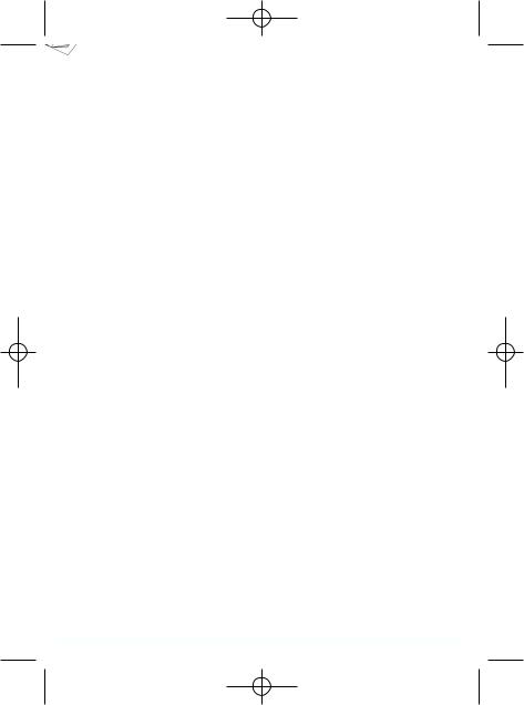
1.Gerätebeschreibung
1.Fräskopf
2.Kreuztisch
3.Maschinensäule
4.Arbeitsspindel
5.Getriebehebel
6.Drehzahlwahlschalter
7.Stellrad für Feinvorschub
8.Ein- / Ausschalter
9.Zahnkranzbohrfutter
10.Handkurbel für Querschlitten
11.Handkurbel für Längsschlitten
12.Tiefenanschlag
13.Befestigungsmutter für Neigungsverstellung
14.Drehkreuz
15.Spindelabdeckung
16.Klappbarer Späneschutz
2. Lieferumfang
Bohr-, Fräsmaschine
Bohrfutterschlüssel
Hakenschlüssel
Fixierstift
Werkzeug
3. Bestimmungsgemäße Verwendung
Diese Maschine ist zum Bohren, Tiefenfräsen und Stirnfräsen von kleinen Werkstücken (max. Abmessungen: 300 mm x 200 mm x 200 mm) aus Metall, Kunststoff oder ähnlichen Materialien bestimmt . Mit dem serienmäßigen Zahnkranzbohrfutter dürfen nur Bohrund Fräswerkzeuge mit einem zylindrischen Schaft von max. 16mm verwendet werden. Bei der Bearbeitung von Metall (ST37) sollte der Werkzeugdurchmesser nicht mehr als 13mm betragen. Es ist zudem auch möglich Werkzeuge mit kegeligem Schaft (MK3) direkt in der Arbeitsspindel aufzunehmen. Diese Bohr-, Fräsmaschine ist nur für den Hausgebrauch geeignet und darf nicht für den industriellen Einsatz verwendet werden. Die Maschine darf nur nach ihrer Bestimmung verwendet werden. Jede weiter darüber hinausgehende Verwendung ist nicht bestimmungsgemäß.
Für daraus hervorgehende Schäden oder Verletzungen aller Art haftet der Benutzer bzw. Bediener und nicht der Hersteller. Bestandteil der bestimmungsgemäßen Verwendung ist auch die Beachtung der Sicherheitshinweise sowie die Montageanleitung
und Betriebshinweise in der Bedienungsanleitung. Personen, die Maschine bedienen und warten, müssen mit dieser vertraut und über mögliche Gefahren unterrichtet werden. Darüber hinaus sind die gelten Unfallverhütungsvorschriften genauestens einzuhalten. Sonstige allgemeine Regeln in arbeitsmedizinischen und sicherheitstechnischen Bereichen sind zu beachten.
Veränderungen an der Maschine schließen eine Haftung des Herstellers und daraus entstehende Schäden gänzlich aus. Trotz bestimmungsmäßiger Verwendung können bestimmte Restrisikofaktoren nicht vollständig ausgeräumt werden. Bedingt durch Konstruktion und Aufbau der Maschinen können folgende Punkte auftreten.
Berührung des Backenfutters in nicht abgedeck ten Bereich.
Eingreifen von rotierende Teile ( Verletzungsgefahr )
Wegschleudern von Werkstücken und Werkstückteilen.
Durch die nicht im Einsatz befindlichen Drehmeißel besteht Verletzungsgefahr.
Werkstücke deren Durchmesser ein Durchschieben des Werkstücks durch das Backfutter in Richtung Spindelstock erlaubt, dürfen keinesfalls hinten über die Maschinenbegrenzung herausragen. ( Verletzungsgefahr )
Gesundheitsschädliche Kühlund Schmiermittel. Beachten Sie auf umweltgerechte Entsorgung.
Berührung rotierender Bauteile im nicht abgedeckten Bereich. Verletzungsgefahr!
Achtung Verletzungsgefahr! Den Backenfutterschlüssen immer sofort wieder Abziehen und niemals stecken lassen!
Wegschleudern von Werkstücken und Werkstückteilen.
Verletzungsgefahr durch das nicht im Einsatz befindliche Fräswerkzeug.
Augenverletzungen durch wegfliegenden Spänen und anderen Splitter. Tragen Sie unbedingt eine Schutzbrille!
7

Anleitung MBF 550 25.02.2005 9:47 Uhr Seite 8
D
4. Wichtige Hinweise
Bitte lesen Sie vor der Inbetriebnahme die Gebrauchsanweisung sorgfältig durch und beachten Sie die Sicherheitshinweise. Machen Sie sich abhand dieser Gebrauchsanweisung mit dem Gerät, dem richtigen Gebrauch sowie den Sicherheitshinweisen vertraut. Bewahren Sie die Gebrauchsanweisung immer so auf, dass es dem Bediener jederzeit zugänglich ist.
Das Tragen einer persönlichen Schutzausrüstung ist bei allen Arbeiten mit der Maschine unbedingt erforderlich.
Tragen Sie zur Vermeidung von Augenverletzungen immer eine Schutzbrille
Tragen sie unbedingt ein Haarnetz oder eine geeignete Arbeitsmütze, wenn Sie lange Haare haben.
Tragen Sie enganliegende Arbeitskleidung.
Das rotierende Werkzeug könnte Ärmel o. a. erfassen.
Benutzen Sie zum Entfernen von Spänen einen geeigneten Spänehacken. Niemals Späne mit bloßer Hand entfernen.
Bei ausgeschalteter Maschine entfernen Sie Späne am besten mit einem Handfeger oder einem Pinsel.
Das Arbeiten mit der Maschine ist nur Personen über 18 Jahren gestattet, die mit dem Umgang der wirkungsweise der Maschine vertraut sind.
Jugendlichen zwischen 16 und 18 Jahren ist das Arbeiten nur unter Aufsicht eines Erwachsenen gestattet.
Überprüfen Sie vor Arbeitsbeginn die korrekte Funktion der Schutzeinrichtung
Überlasten Sie die Maschine nicht. Sie arbeiten besser und sicherer im angegebenen Leistungsbereich.
Benutzen Sie das richtige Werkzeug und achten Sie drauf, dass die Werkzeuge (Drehmeißel, Bohrer) nicht stumpf oder abgebrochen sind.
Kabel immer hinten von der Maschine wegführen. Schützen Sie das kabel vor Hitze, Öl und scharfen Kanten.
Ziehen Sie den Netzstecker bei Reparaturen und Wartungsarbeiten und wenn Sie die Maschine nicht benutzen.
Arbeiten an elektrischen Einrichtungen dürfen nur von einer Elektrofachkraft vorgenommen werden. Es dürfen nur Orginalteile verwendet werden.
Saubere Arbeitsplätze erleichtern das Arbeiten. Achten sie darauf, was Sie tun. Gehen Sie mit
8
Vernunft an die Arbeit.
Achten Sie darauf, dass der Unterbau das Gewicht der Maschine tragen kann und ausreichend stabil ist, damit beim Bearbeiten keine Schwingungen auftreten können.
Zum Schutz vor Korrosion sind alle blanken Teile der Maschine werkseitig stark eingefettet. Reinigen Sie die Maschine vor der Inbetriebnahme mit einem geeignetem umweltfreundlichen Reinigungsmittel.
Achtung! Schließen Sie die Schutzabdeckung für das Backenfutter bevor Sie die Maschine einschalten.
Mit der Maschine dürfen keine gesundheitsgefährdenden oder Stauberzeugenden Materialien, wie z.B. Holz, Teflon etc. bearbeitet werden.
Benutzen Sie die Maschine nicht in der Nähe von brennbaren Flüssigkeiten oder Gasen.
Verwenden Sie die Maschine nur in geeigneten Räumen und setzen Sie die Maschine nicht feuchten oder nassen Umgebungen aus.
Sorgen Sie beim arbeiten für gute Beleuchtung.
Benutzen Sie das Kabel nicht um den Stecker aus der Steckdose zu ziehen.
Achten Sie darauf, dass beim Arbeiten das Werkstück fest eingespannt ist. Werkstück immer in einem Maschinenschraubstock oder mit Hilfe von Spannpratzen festspannen.
Verwenden Sie nur scharfe und saubere Werkzeuge.
Schalten Sie die Maschine bei gefährlichen Situationen oder technischen Störungen sofort aus und ziehen Sie den Netzstecker!
Bei Beschädigungen darf mit der Maschine nicht mehr gearbeitet werden und es muss der Netzstecker gezogen werden!
Achtung! Es dürfen nur vom Hersteller freigegebene Einsatzwerkzeuge und Zubehör verwendet werden. Die Verwendung von nicht freigegebenen Teilen kann eine Verletzungsgefahr für Sie bedeuten.
Halten Sie Ihren Arbeitsbereich sauber und in Ordnung. Unordnung im Arbeitsbereich kann Unfälle verursachen.
Schutzbrille tragen. Bei Arbeiten mit starker Staubbildung muss außerdem eine Gesichtsbzw. Staubmaske verwendet werden.
Futterschlüssel und anderes Werkzeug vor Arbeitsbeginn entfernen.

Anleitung MBF 550 25.02.2005 9:47 Uhr Seite 9
D
5. Technische Daten
Nennspannung |
|
230 V ~ / 50 Hz |
|
Nennleistung |
550 W S3 50% 400W S1 |
||
Drehzahlbereich (L) niedrig |
50–1.100 |
min-1 |
|
Drehzahlbereich (H) hoch |
|
120–2.500 min-1 |
|
Morsekegel in Spindel |
|
MK 3 |
|
|
|
|
|
Max. Bohrdurchmesser |
|
16 |
mm |
|
|
|
|
Fingerfräserdurchmesser |
|
13 |
mm |
Stirnfräserdurchmesser |
|
30 |
mm |
|
|
|
|
Kreuztisch |
|
410 x 110 mm |
|
|
|
|
|
Max. Tischverstellung in x |
|
250 mm |
|
|
|
|
|
Max. Tischverstellung in y |
|
100 mm |
|
|
|
|
|
Max. Spindelhub |
|
220 |
mm |
Winkelverstellung l/r |
|
-45° - +45° |
|
|
|
|
|
Schalldruckpegel LPA |
|
83 dB(A) |
|
|
|
|
|
Schutzart |
|
IP 23 |
|
|
|
|
|
Gewicht |
|
62 kg |
|
Betriebsart S3 (Periodischer Aussetzbetrieb):
Die Maschine darf eine bestimmte Zeit (relative Einschaltdauer in % der Spieldauer) mit Nennleistung in Betrieb genommen werden. Danach muss die Maschine eine Zeitspanne stillstehen (Pausezeit) um sich nicht unzulässig zu erwärmen. Die Spieldauer setzt sich aus Belastungsdauer und Pausendauer zusammen. Während des Stillstandes zwischen den Spieldauern kühlt sich die Maschine nicht mehr auf Raumtemperatur ab. Die Spieldauer beträgt 10min, wenn keine andere Angabe gemacht wird.
6. Inbetriebnahme
Achtung!
Ziehen Sie vor sämtlichen Montagen und Einstellarbeiten den Netzstecker.
Um Transportschäden zu vermeiden darf die Maschine nur aufrecht , am besten in der Originalverpackung, transportiert werden!
Maschinengewicht beachten! Das Nettogewicht der Maschine beträgt 62 kg. Verwenden sie ein geeignetes Transportmittel, welches die Last der Maschine aufnehmen kann. Sollte kein Transportmittel zur Verfügung stehen, heben Sie die Maschine vorsichtig an, damit Mensch und Maschine nicht zu Schaden kommen.
Schützen Sie die Maschine vor Feuchtigkeit und Regen.
Die Aufstellung und Verwendung der Maschine ist nur in trockenen und belüfteten Räumen zulässig. Der Temperaturbereich für Betrieb der Maschine sollte zwischen +15° und +40° liegen.
Sind Werkzeugfutter und Fräser ausreichend befestigt?
Kontrollieren Sie, ob sich eventuell Maschinenteile gelöst haben.
Würde der richtige Drehzahlbereich gewählt?
Sind Maschine und Spannmittel sauber und frei von Spänen?
Kontrollieren Sie, ob die Befestigungsschrauben des Dreibackenfutters fest angezogen sind und ob sich die Arbeitsspindel leicht von der Hand drehen lässt.
Vor der Inbetriebnahme müssen alle Abdeckungen und Sicherheitsvorrichtungen montiert sein.
Das Backfutter muß frei laufen können.
Bevor Sie den Einschalter betätigen vergewissern Sie sich das alles richtig montiert und bewegliche Teile leichtgängig sind.
Überzeugen Sie sich vor dem Anschließen der Maschine, daß die Daten auf dem Typenschlid mit den Netzdaten übereinstimmen.
6.2 Aufstellung
Stellen Sie die Maschine auf einen ebenen Unterbau (Werkbank etc.)
Wichtig: Die Maschine muss mit vier Schrauben fest mit dem Unterbau verschraubt werden. Benutzen Sie dazu die vier Befestigungsbohrungen in der Standplatte der Maschine.
Stellen Sie sicher dass genügend Platz zur verfahren des Kreuztisches und für Neigungseinstellungen vorhanden ist.
Achten Sie darauf, dass der Unterbau der Maschine ausreichend stabil ist um das Gewicht (ca. 62 kg) der Maschine zu tragen!
Zum Schutz vor Korrosion sind alle blanken Teile der Maschine werkseitig eingefettet. Reinigen Sie die Maschine vor Inbetriebnahme mit einem geeigneten, umweltfreundlichen Reinigungsmittel. Benutzen Sie keine Reinigungsmittel die den Lack der Maschine angreifen könnten und sorgen Sie während der Reinigung für ausreichende Belüftung. Ölen Sie nach erfolgter Reinigung die Maschine wieder leicht mit säurefreiem Schmieröl ein!
Achtung: Öl, Fett und Reinigungsmittel sind umweltgefährdend und müssen Umweltgerecht entsorgt werden – nicht in den Hausmüll geben!
9

Anleitung MBF 550 25.02.2005 9:47 Uhr Seite 10
D
6.3 Netzanschluss / Schalter
Die Maschine darf nur mit Einphasenstrom 230 Volt / 50 Hz berieben werden. Hausseitig muss der Stromkreis mit maximal 16 A abgesichert sein.
6.3.1 Maschine Einschalten (Abb. 3)
Vor dem Einschalten der Maschine muss der klappbare Späneschutz (16) heruntergeklappt sein.
Zum Einschalten muss die grüne Taste (I) gedrückt werden.
Leuchtet die grüne Kontrollleuchte (a) kann die Maschine mittels des Drehzahl-Wahlschalters (6) eingeschaltet und die gewünschte Drehzahl eingestellt werden.
Leuchtet zusätzlich die orange Kontrollleuchte (b), muss der Drehzahl-Wahlschalter (6) erst in „0“ Position gestellt werden und die gelbe Leuchte erlischt wieder. Danach kann die gewünschte Drehzahl an der Maschine eingestellt werden und die Maschine läuft an.
6.3.2 Maschine Ausschalten
Maschine durch Drücken der roten „O“ Taste oder durch drücken der „NOT AUS TASTE“ (c) ausschalten und durch das ziehen des Netzsteckers vom Netz trennen.
7. Bedienung und Einstellung
Achtung: Alle Einstellungen an der Maschine dürfen nur bei gezogenem Netzstecker vorgenommen werden.
7.1 Drehzahleinstellung
Mittels des Getriebehebels (5) auf der Maschinenseite können zwei Drehzahlbereiche gewählt werden.
Vordere Stellung (L) für den Drehzahlbereich
50 bis 1100 min-1 Hintere Stellung (H) für den Drehzahlbereich
120 bis 2500 min-1
Achtung: Drehzahlbereiche (L und H) nicht bei laufender Spindel ändern! Die Drehzahl kann innerhalb des Drehzahlbereiches stufenlos eingestellt werden. Die Feineinstellung der Drehzahl erfolgt über den Drehzahlwahlschalter (6).
7.2 Richtigen Drehzahl / Schnittgeschwindigkeit
Die Wahl der richtigen Schnittgeschwindigkeit hat große Auswirkungen auf die Standzeit des Werk-
10
zeuges und auf das Arbeitsergebnis. Sie ist je nach Werkstoff unterschiedlich zu wählen. Die richtige Schnittgeschwindigkeit erhalten Sie durch die richtige Wahl der Drehzahl.
7.2.1 Bohren
Faustregel: Je kleiner die Löcher und je weicher der Werkstoff, desto höher die Drehzahl.
Unten aufgeführte Liste hilft ihnen bei der Wahl der Richtigen Drehzahl für die verschiedenen Materialien.
Bei den angegebenen Drehzahlen handelt es sich lediglich um Richtwerte.
Drehzahleinstellung siehe Kap.7.1
Ø Bohrer |
Grauguss |
Stahl |
Eisen |
Aluminium |
Bronze |
3 |
2550 |
1600 |
2230 |
9500 |
8000 |
4 |
1900 |
1200 |
1680 |
7200 |
6000 |
5 |
1530 |
955 |
1340 |
5700 |
4800 |
6 |
1270 |
800 |
1100 |
4800 |
4000 |
7 |
1090 |
680 |
960 |
4100 |
3400 |
8 |
960 |
600 |
840 |
3600 |
3000 |
9 |
850 |
530 |
740 |
3200 |
2650 |
10 |
765 |
480 |
670 |
2860 |
2400 |
11 |
700 |
435 |
610 |
2600 |
2170 |
12 |
640 |
400 |
560 |
2400 |
2000 |
13 |
590 |
370 |
515 |
2200 |
1840 |
14 |
545 |
340 |
480 |
2000 |
1700 |
16 |
480 |
300 |
420 |
1800 |
1500 |
18 |
425 |
265 |
370 |
1600 |
1300 |
20 |
380 |
240 |
335 |
1400 |
1200 |
22 |
350 |
220 |
305 |
1300 |
1100 |
25 |
305 |
190 |
270 |
1150 |
950 |
7.2.2 Fräsen
Die Drehzahl lässt sich folgendermaßen berechnen:
n = v / ( x d )
n = Drehzahl in min-1
v = Schnittgeschwindigkeit in m/min d = Werkzeugdurchmesser in m
= 3,14
Die Werte für die Schnittgeschwindigkeiten und maximalen Schnitttiefen für den jeweiligen Werkstoff entnehmen Sie unten aufgeführter Liste oder einem Tabellenbuch.
Anleitung MBF 550 25.02.2005 9:47 Uhr Seite 11
|
|
Schnellarbeitsstahl |
Hartmetall |
|
||||||
|
|
Schnitt- |
Schnitt- |
Schnitt- |
Schnitt- |
|||||
Werkstoff |
Zugfestigkeit |
tiefe a |
geschwindigkeit |
tiefe a |
geschwindigkeit |
|||||
|
|
[mm] |
v [m/min] |
[mm] |
v [m/min] |
|||||
|
|
0,5 |
70 |
- |
50 |
1 |
200 |
- |
150 |
|
|
500 - 700 |
3 |
50 |
- |
30 |
6 |
100 - 70 |
|||
All. Baustahl, |
|
10 |
30 |
- |
20 |
10 |
70 |
- |
50 |
|
|
0,5 |
45 |
- |
30 |
1 |
150 |
- |
110 |
||
Werkzeug- |
|
|||||||||
700 - 900 |
3 |
30 |
- |
20 |
6 |
80 |
- |
55 |
||
stahl, Einsatz |
||||||||||
|
10 |
18 |
- |
12 |
10 |
55 |
- |
35 |
||
und |
|
0,5 |
30 |
- |
20 |
1 |
110 - 75 |
|||
Vergütungs- |
|
|||||||||
900 - 1100 |
3 |
20 |
- |
15 |
6 |
55 |
- |
35 |
||
stahl, |
||||||||||
|
10 |
18 |
- |
10 |
10 |
35 |
- |
25 |
||
Stahlguss |
|
- |
|
- |
|
1 |
75 |
- |
50 |
|
|
1100 - 1400 |
- |
|
- |
|
3 |
50 |
- |
30 |
|
|
|
- |
|
- |
|
6 |
30 |
- |
20 |
|
Automaten- |
700 |
0,5 |
90 |
- |
40 |
1 |
160 - 80 |
|||
stahl |
3 |
75 |
- |
30 |
3 |
120 - 60 |
||||
|
|
0,5 |
45 |
- |
35 |
1 |
100 - 80 |
|||
Gusseisen |
200 |
3 |
35 |
- |
25 |
3 |
90 |
- |
60 |
|
mit Lamellen- |
|
10 |
20 |
- |
15 |
10 |
60 |
- |
40 |
|
graphit |
200 - 400 |
0,5 |
40 |
- |
30 |
1 |
100 - 70 |
|||
|
3 |
30 |
- |
20 |
3 |
70 |
- |
50 |
||
Schwarzer |
|
0,5 |
70 |
- |
45 |
1 |
240 |
- |
190 |
|
350 |
3 |
60 |
- |
40 |
3 |
190 |
- |
140 |
||
Temperguss |
||||||||||
|
6 |
40 |
- |
20 |
6 |
140 - 80 |
||||
Weißer |
|
0,5 |
60 |
- |
40 |
1 |
150 |
- |
100 |
|
350 - 400 |
3 |
50 |
- |
35 |
3 |
100 - 60 |
||||
Temperguss |
||||||||||
|
6 |
35 |
- |
20 |
6 |
70 |
- |
45 |
||
|
|
0,5 |
180 |
- |
160 |
0,5 |
700 + |
|||
|
60 - 320 |
3 |
160 |
- |
140 |
3 |
600 |
- |
400 |
|
Aluminium |
|
6 |
140 |
- |
120 |
6 |
500 |
- |
250 |
|
320 - 440 |
1 |
140 |
- |
100 |
1 |
400 |
- |
200 |
||
Legierungen |
||||||||||
6 |
120 - 80 |
6 |
300 |
- |
150 |
|||||
|
440 + |
- |
|
- |
|
1 |
200 |
- |
120 |
|
|
- |
|
- |
|
6 |
150 - 50 |
||||
|
200 - 400 |
3 |
150 |
- |
100 |
3 |
450 |
- |
350 |
|
Kupfer |
6 |
120 - 70 |
6 |
350 |
- |
250 |
||||
Legierungen |
400 - 800 |
3 |
100 - 55 |
3 |
400 |
- |
300 |
|||
|
6 |
55 |
- |
35 |
6 |
30 - 200 |
||||
|
|
|
|
|
|
|
|
|
|
|
7.3 Spannen der Werkzeuge (Abb. 4,5,6)
In der Arbeitsspindel dürfen ausschließlich Werkzeuge, Spannvorrichtungen oder Werkzeugaufnahmen mit Morsekegel MK3 und Innengewinde M12 zu formschlüssigen Befestigung verwendet werden. Reduzierhülsen dürfen nicht verwendet werden!
7.3.1 Werkzeuge in Arbeitsspindel spannen
Maschine ausschalten und Netzstecker ziehen!
Spindelabdeckung (15) entfernen.
Kegelschaft und Spindel säubern und entfetten.
Jetzt den Kegelschaft (18) in die Hülse der Arbeitsspindel (4) stecken. Achtung: Um Verletzungen zu vermeiden sollte der Fräser mit einem Lappen angefasst werden!
Zum Fixieren der Arbeitsspindel den Fixierstift (17) seitlich in die Spindelhülse einstecken.
Zugstange (19) zum Befestigen des Kegelschaftes mit einem Maulschlüssel (SW10) festziehen. Die Zugstange muss mit ca. 8 Umdrehungen (im Uhrzeigersinn) in den Kegeldorn geschraubt werden. Wichtig: Sichern Sie das Werkzeug oder das Bohrfutter immer mit der Zugstange, um ein selbstständiges Lösen des Werk-
D
zeuges auszuschließen.
Fixierstift (17) wieder entfernen.
Spindelabdeckung (15) wieder aufstecken.
7.3.2 Werkzeug aus Arbeitsspindel entfernen:
Maschine ausschalten und Netzstecker ziehen!
Spindelabdeckung (15) entfernen.
Zum Fixieren der Arbeitsspindel den Fixierstift (17) seitlich in die Spindelhülse einstecken.
Zugstange mit Maulschlüssel (SW 10) entgegen dem Uhrzeigersinn lösen.
Kegelschaft (18) vorsichtig mit einem Gummihammer lockern und aus der Spindelhülse nehmen. Um Verletzungen zu vermeiden sollte der Fräser mit einem Lappenangefasst werden!
Spindelabdeckung (15) wieder aufsetzen.
7.3.3 Handhabung des Bohrfutters
Im Bohrfutter (9) dürfen nur zylindrische Werkzeuge mit dem angegebenen maximalen Schaftdurchmesser gespannt werden. Nur einwandfreies und scharfes Werkzeug benutzen. Keine Werkzeuge benutzen, die an Schaft beschädigt sind oder sonst in irgendeiner Weise verformt oder beschädigt sind. Setzen Sie nur Zubehör oder Zusatzgeräte, die vom Hersteller freigegeben sind, ein.
Schaft des Werkzeuges ganz in das Bohrfutter (9) einstecken und mit dem mitgelieferten Futterschlüssel festziehen.
Futterschlüssel wieder abziehen. Achten Sie auf festen Sitz der eingespannten Werkzeuge. Achtung: Futterschlüssel nicht stecken lassen. Verletzungsgefahr durch Wegschleudern des Futterschlüssels.
7.4 Spannen der Werkstücke
Achtung: Die Werkstücke müssen immer fest eingespannt werden! Dies ist wichtig für die Betriebssicherheit und für das Arbeitsergebnis.
Ist das Werkstück nicht fest eingespannt, kann es durch die Vorschubkraft des Fräsers herausgerissen und weggeschleudert werden.
Am besten eignet sich hierzu ein
Maschinenschraubstock.(nicht im Lieferumfang enthalten. Mit Hilfe von Spannschrauben und Nutsteinen kann der Maschinenschraubstock fest am Kreuztisch der Maschine befestigt werden. Vor dem endgültigen festziehen der Schrauben muss der Maschinenschraubstock mittels eine Messuhr genau parallel zu den Schlittenführungen ausgerichtet werden.
11

Anleitung MBF 550 25.02.2005 9:47 Uhr Seite 12
D
Es können auch geeignete Spannpratzen (nicht im Lieferumfang enthalten), zum befestigen des Werkstückes am Maschinentisch verwendet werden. Dabei ist auf die richtige Spannpratzengröße zu achten., um eine festen Halt des Werkstückes zu gewährleisten.
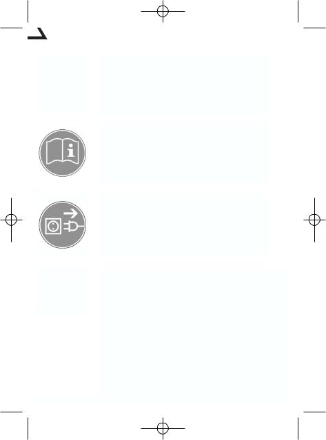
7.5 Vorschub (Abb.7,8)
Alle Vorschubbewegungen müssen von Hand ausgeführt werden.
7.5.1 Normalvorschub des Fräskopfes (Abb. 1/2/7)
Das Drehkreuz (14) des Vorschubes ganz von der Maschine weg nach außen ziehen.
Das Werkzeug kann nun mittels des Drehkreuzes schnell an das Werkstück herangeführt werden.
Der Normalvorschub wird zum Ausführen von Bohrungen verwendet.
Durch den Tiefenanschlag (12) kann die Bohrbzw. Frästiefe in z-Richtung begrenzt werden.
Dazu Feststellgriff (20) am Tiefenanschlag (12) lösen
Tiefenanschlag auf die gewünschte Position einstellen und Feststellgriff (20) wieder festziehen.
Die Vorschubposition kann an der Skala (21) abgelesen werden.
7.5.2 Feinvorschub des Fräskopfes (Abb. 1/7)
Das Drehkreuz (14) so in Richtung Fräskopf (1) schieben, dass die Zähne der Klauenkupplung
(27)ineinander greifen.
Der Fräser kann nun mittels des Stellrades für den Feinvorschub (7) genau positioniert werden.
Ein Teilstriches des Skalenrings entspricht 0,02 mm Verfahrweg des Tisches.
Ist die gewünschte Frästiefe eingestellt muss der Fräskopf (1) mittels des jeweiligen Klemmhebels
(28)fixiert werden.
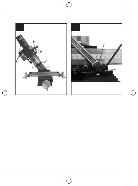
7.5.3 Vorschub des Kreuztisches (Abb. 8)
Der Kreuztisch (2) der Maschine ist in zwei senkrecht zueinander stehenden Achsen (X;Y) manuell verfahrbar.
Der Vorschub beim Fräsen wird durch Betätigung der Kurbeln (10;11) ausgeführt.
Durch den Skalenring an den Handkurbeln kann man die Nullposition des Verfahrweges einstellen.
Ein Teilstriches des Skalenrings entspricht 0,02 mm Verfahrweg des Tisches.
Wird eine Verfahrachse (X oder Y) des Tisches nicht verwendet, empfiehlt es sich diese mittels des jeweiligen Klemmhebels (22) festzuklemmen.
12
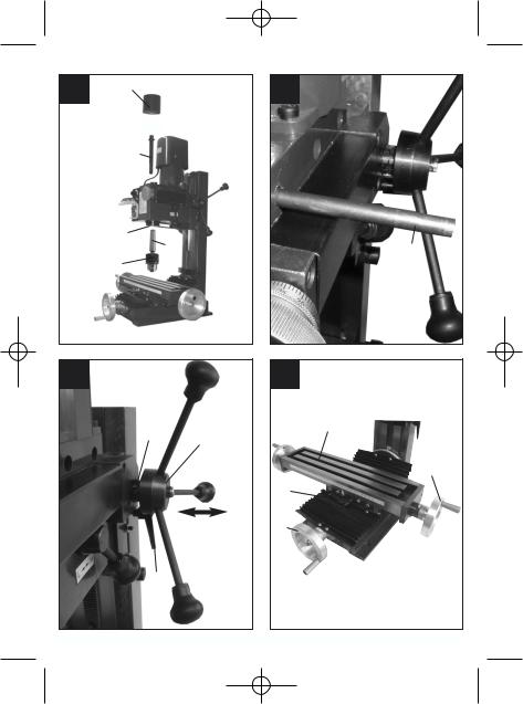
7.6 Schwenken des Fräskopfes (Abb. 1,2, 9)
Zum Fräsen von Fasen oder V-Nuten kann der Fräskopf nach links und rechts um jeweils 45° geschwenkt werden.
Achtung: Stellen Sie vor Beginn der Einstellung sicher, dass die Maschine fest auf der Arbeitsfläche verschraubt ist!
Maschine ausschalten.
Maschinenkopf (1) mit einer Hand gut festhalten um ein Wegkippen zu verhindern.
Befestigungsmutter (13) mit einem Maulschlüssel (SW 32) lösen.
0° Arretierung (23) durch herausziehen entriegeln.
Den gewünschten Keilwinkel an der Winkelskala (24) einstellen.
Befestigungsmutter (13) wieder festziehen.
7.7 Gehrungsführungen justieren (Abb. 10)
Bei häufiger Benutzung kann sich der Abstand zwischen den Gleitflächen des Längsund Querschlittens sowie des Fräskopfes ändern. Um die einwandfreie Funktion und Bewegung zu gewährleisten sollte die Gehrungsführungen etwa 1 mal pro Jahr nachjustiert werden.
Kontermuttern (25) lösen
Justierschrauben (26) so nachstellen, dass der ausgeübte Druck auf die Gehrungsführung an jeder Justierschraube gleichmäßig ist.
Justierschraube (26) mittels eines Inbusschlüssels (3mm) in Position halten und Kontermuttern (25) wieder festziehen.
Tip: Die Justierschrauben von außen beginnend immer von zwei Seiten gleichmäßig anziehen, um eine einheitliche Einstellung zu erhalten.
8. Bearbeitung
8.1 Bohren und Tiefenfräsen
Bohrfutter und Werkzeug wie in Kap. 7.2 beschrieben einsetzen und mit der Zugstange sichern.
Bohrfutter mit Hilfe des Futterschlüssels festziehen.
Richtigen Drehzahl einstellen (siehe Kap. 7 )
Spannen Sie das Werkstück gut mittels eines Maschinenschraubstockes oder mittels Spannpratzen gut fest.
Kreuztisch (2) in die (X- und Y-Richtung) in die gewünschte Position bringen
Tiefenanschlag einstellen (siehe Kap. 7) und dar-

Anleitung MBF 550 25.02.2005 9:47 Uhr Seite 13
auf achten dass das Werkzeug nicht das Werkstück berührt.
Nicht mehr gebrauchte Gegenstände aus dem Arbeitsbereich entfernen.
Maschine einschalten und mit dem Drehzahlwahlschalter (6) die richtige Spindeldrehzahl einstellen.
Durchführen der Bohrbzw. Fräsarbeit. Hinweis: Bei großen Bohrungen sollte zuerst mit einem kleinen Bohrer vorgebohrt werden. Ziehen Sie den Bohrer während des Bohrens einige Male aus dem Werkstück zurück, damit das Bohrloch frei von Spänen bleibt.
Die Bohrbzw. Frästiefe ergibt sich aus der Einstellung des Tiefenanschlages (12)
Nach Beendigung der Arbeit Fräskopf wieder in obere Position bringen und Maschine ausschalten.
Maschine und Spannvorrichtung reinigen und ggf. einölen.
8.1.1 Senken und Zentrierbohren
Bitte beachten Sie dass Senken mit niedriger Schnittgeschwindigkeit und niedrigem Vorschub, während Zentrierbohren mit hoher Schnittgeschwindigkeit und niedrigem Vorschub durchzuführen ist.
8.2 Stirnfräsen
Spannfutter und Werkzeug einspannen (siehe Kap. 7.1) und mit der Zugstange (19) sichern.
Spannfutter mit Hilfe des Futterschlüssels festziehen.
Richtigen Drehzahlbereich einstellen (siehe Kap. 7)
Achtung: Drehzahlbereiche (L und H) nicht bei laufender Spindel ändern!
Spannen Sie das Werkstück gut mittels eine Maschinenschraubstockes oder mittels Spannpratzen gut fest.
Arbeitstisch in die (X- und Y-Richtung) in die gewünschte Position bringen
Tiefenanschlag einstellen (siehe 7.4.1) und darauf achten dass das Werkzeug nicht das Werkstück berührt.
Nicht mehr gebrauchte Gegenstände aus dem Arbeitsbereich entfernen.
Maschine einschalten und mit dem Drehzahlwahlschalter(6) die gewünschte Spindeldrehzahl einstellen.
Fräsarbeit durchführen. Dazu Kreuztisch mittels der Handkurbeln in X- und Y-Richtung verstellen. (siehe 7.5.3)
Nach Beendigung der Arbeit Maschine ausschalten und Fräskopf (1) wieder in obere Position
D
bringen.
Maschine und Spannvorrichtung von reinigen und ggf. einölen.
Nach dem Gebrauch der Maschine muss der Arbeitstisch wieder gereinigt und eingeölt werden.
9. Pflege und Wartung
Vor allen Pflege und Wartungsarbeiten ist der Netzstecker zu ziehen! Die Maschine ist in regelmäßigen Abständen (je nach Benutzungshäufigkeit) zu warten. Die Wartungsarbeiten sollten genau dokumentiert werden.
Kegelschäfte und Fräser sauber halten.
Zum Schutz, gleiche Fräser bei Nichtgebrauch am besten in einer Box aufbewahren.
Überprüfen Sie den gesamten Stromkreis ( Schalter, Stecker, Kontakte etc.) auf ordnungsgemäße Funktion.
Um größeren Schäden und Verletzungen vorzubeugen, wenden Sie sich bei Störungen, welche über die normale Wartung hinausgehen, bitte an unsere Kundendienst. Die Serviceadresse finden Sie nachfolgend in der Garantieurkunde.
Überprüfen Sie den Fräsmaschinenkopf auf leichte Beweglichkeit und achten Sie darauf dass er sich nicht gelockert hat.
Prüfen Sie die Spindel auf Überschwingen.
Alle Schraubverbindungen auf festen Sitz überprüfen.
9.1 Schmierung
Um stets gute Arbeitsergebnisse zu gewährleisten und die Maschine vor Korrosion zu schützen, muss die Maschine in regelmäßigen Abständen abgeschmiert und gefettet werden. Verteilen Sie das Schmieröl bzw. Schmierfett gleichmäßig mit einem Pinsel oder einem nicht fusselnden Lappen.
Schmierstellen und Schmierstoffe: |
|
Alle blanken Maschinenteile: |
Schmieröl |
Zahnstange an Säule: |
Schmieröl |
Maschinentisch: |
Schmieröl |
Mechanismus des Feinvorschubes: |
Schmieröl |
Vorschubspindel Längsschlitten: |
Schmieröl |
Vorschubspindel Querschlitten: |
Schmieröl |
Prismenführung Fräskopf: |
Schmierfett |
Drehlager Fräskopf: |
Schmierfett |
Prismenführung Querschlitten: |
Schmierfett |
Prismenführung Längsschlitten: |
Schmierfett |
|
13 |

Anleitung MBF 550 25.02.2005 9:47 Uhr Seite 14
D
Sonderzubehör:
Für die Maschine ist folgendes Zubehör erhältlich:
Maschinenschraubstock
SpannpratzenSet (58 tlg)
Spannzangen Set 4-16 mm (9 tlg
Wendeschneidplattenfräser Ø 30 mm
Wendeschneidplatten Hartmetall
10. Ersatzteilbestellung
Ersatzteile können bei der Fa. ISC GmbH bestellt werden (Adresse siehe Garantieurkunde), hierbei sollten folgende Angaben gemacht werden:
Typ des Gerätes
Artikelnummer des Gerätes
IdentNummer des Gerätes
ErsatzteilNummer des erforderlichen Ersatzteils
Aktuelle Preise und Infos finden Sie unter:
www.isc-gmbh.info
14

Anleitung MBF 550 25.02.2005 9:47 Uhr Seite 15
GB
1. Layout
1.Routing head
2.Compound table
3.Machine column
4.Work spindle
5.Gear lever
6.Speed selector switch
7.Wheel selector for fine feed
8.ON/OFF switch
9.Ring gear drill chuck
10.Hand crank for cross slide
11.Hand crank for saddle slide
12.Depth stop
13.Fixing nut for angle adjustment
14.Star handle
15.Spindle guard
16.Hinged chip guard
2. Items supplied
Drilling and routing machine
Drill chuck key
Hook spanner
Locating pin
Tools
3. Proper use
This machine is designed for the drilling, deep routing and face routing of small workpieces (max. dimensions: 300 mm x 200 mm x 200 mm) made from metal, plastic or similar materials. Only drilling and routing tools with a cylindrical shaft of max. 16 mm may be used with the standard ring gear drill chuck. The tool diameter for the machining of metal (ST37) must be no more than 13 mm. Tools with a tapered shank (MK3) can also be mounted directly in the work spindle. This drilling and routing machine is suitable only for household use and must not be used for industrial applications. The machine is to be used only for its prescribed purpose. Any other use is deemed to be a case of misuse.
The user/operator and not the manufacturer will be held liable for damage and/or injuries of any kind that result from such misuse. To use the machine properly you must also observe the safety regulations, the assembly instructions and the operating instructions to be found in this manual. All persons who use and service the machine have to be acquainted with this manual and must be informed about the machine’s potential hazards. It is also imperative to observe the accident prevention regulations in force in your area.
The same applies for the general rules of health and safety at work.
The manufacturer will not be liable for any changes made to the machine nor for any damage resulting from such changes. Even when the machine is used as prescribed it is still impossible to eliminate certain residual risk factors. The following hazards may arise in connection with the machines’ construction and design:
Contact with the jaw chuck where it is not covered.
Reaching into rotating parts (risk of injury).
Catapulting of workpieces and parts of workpieces from the machine.
Risk of injury from the cutting tool even when it is not being used.
Workpieces whose diameter allows them to fall through the jaw chuck towards the spindle head must not under any circumstances project beyond the limit of the machine (risk of injury).
Harmful coolants and lubricants. Make sure they are disposed of in an environmentally friendly manner.
Contact with rotating components where they are not covered. Risk of injury!
Caution! Risk of injury! Always withdraw jaw chuck keys immediately and never leave them inserted in the chuck!
Catapulting of workpieces and parts of workpieces from the machine.
Risk of injury from the routing tool even when it is not in use.
Eye injuries can be caused by flying chips and other splinters. You MUST wear safety goggles!
4. Important information
Please read the directions for use carefully and observe the safety information before using the machine for the first time. It is important to consult these instructions in order to acquaint yourself with the machine, its proper use and safety precautions. Always keep the instructions so that the user can access them at any time.
It is absolutely essential that personal protective equipment is worn whenever working with the machine.
To prevent eye injuries, always wear safety goggles.
You must wear a hair net or suitable work cap if you have long hair.
15

Anleitung MBF 550 25.02.2005 9:47 Uhr Seite 16
GB
Wear close-fitting work clothes.
The tool could catch sleeves etc. as it rotates.
Use a suitable chip hook to remove chips. Never remove chips using just your hand.
With the machine switched off, chips are best removed using a brush or the like.
Only people over the age of 18 who are familiar with how the machine works may operate the machine.
Young people aged between 16 and 18 may only work with the machine under the supervision of an adult.
Check that the safeguard is functioning properly before starting work.
Do not overload the machine. Electric tools work better and safer when used within their quoted capacity range.
Use the correct tool and make sure that the tools (routing tool, drill) are not blunt or broken.
Always lead the power cable from the rear of the machine. Protect the cable from heat, oil and sharp edges.
Pull out the power plug before carrying out repairs and maintenance and when the machine is not in use.
Work on electrical equipment may only be carried out by a qualified electrician. Only original parts may be used.
Clean workplaces make work easier. Concentrate on what you are doing. Use common sense when working.
Make sure that the base on which the machine is placed can support the weight of the machine and is sufficiently stable for no vibrations to occur during machining.
All bare parts of the machine are already well greased in order to protect them from corrosion. Clean the machine with a suitable environmentally friendly cleaning agent before using it for the first time.
Important! Close the safety guard for the jaw chuck before switching the machine on.
This machine must not be used for the machining of any materials that are toxic or generate dust such as wood, Teflon etc.
Do not use the machine near flammable liquids or gases.
Use the machine only in suitable rooms and do not expose the machine to moist or wet environments.
Provide good lighting while you work.
Do not use the cable to pull the plug out of the socket.
Make sure that the workpiece is clamped in firmly
16
when working. Always clamp the workpiece in a machine vice or by means of clamping claws.
Use only tools that are sharp and clean.
Switch the machine off immediately in dangerous situations or if technical faults occur and pull out the power plug!
If the machine is damaged, you must stop working with it and pull out the power plug.
Important! Only replacement tools and accesso ries which have been approved by the manufacturer may be used. The use of nonapproved parts can put you at risk of injury.
Keep your work area clean and tidy. Untidy work areas can cause accidents.
Wear safety goggles. You must also wear a face or dust mask when carrying out work that produces a lot of dust.
Remove jaw keys and other tools before starting work.
5. Technical data
Rated voltage |
|
230 V ~ / 50 Hz |
|
Power rating |
550 W S3 50% 400W S1 |
|
|
Rotational speed range (L) low |
50-1100 min-1 |
|
|
Rotational speed range (H) high |
120-2500 min-1 |
|
|
Morse taper in spindle |
|
MK 3 |
|
Max. drill bit diameter |
|
16 mm |
|
End-routing cutter diameter |
|
13 mm |
|
|
|
||
Face-routing cutter diameter |
30 mm |
||
|
|
|
|
Compound table |
|
410 x 110 mm |
|
Max. table adjustment in x |
|
250 mm |
|
Max. table adjustment in y |
|
100 mm |
|
|
|
|
|
Max. spindle stroke |
|
220 mm |
|
Angle adjustment l/r |
|
-45° - +45° |
|
LPA sound pressure level |
|
83 dB(A) |
|
Protection type |
|
IP 23 |
|
|
|
|
|
Weight |
|
62 kg |
|
Operating mode S3 (periodic intermittent operation):
The machine may be operated at the power rating for a certain period (relative ON period as % of cycle time). Afterwards the machine must be stopped for a while (rest period) to prevent it from overheating. The cycle time is made up of the load period and the rest period. The machine will not cool down to room temperature while not running between the cycle times. Unless stated otherwise, the cycle time is 10 minutes.

Anleitung MBF 550 25.02.2005 9:47 Uhr Seite 17
GB
6. Starting up
Important!
Pull out the power plug before carrying out any assembly and adjustment work.
To avoid damage in transit, always transport the machine upright and preferably in the original packaging.
Make allowance for the weight of the machine! The net weight of the machine is 62 kg. Use suitable means of transport that can support the weight of the machine. Should no means of transport be available, lift the machine carefully so as to avoid injury to people and damage to the machine itself.
Protect the machine against moisture and rain.
The machine may only be installed and used in dry, well-ventilated rooms. The temperature range for operating the machine should be between +15° and +40°.
Are the tool chuck and routing cutter sufficiently secure?
Check to see if any parts of the machine have worked loose.
Has the right rotational speed range been chosen?
Are the machine and clamping devices clean and free of chips?
Check to make sure that the fixing screws of the concentric chuck have been tightened and that the work spindle can be easily rotated by hand.
All covers and safety devices must be properly fitted before the machine is switched on.
The jaw chuck must be able to run freely.
Before switching on, make sure that everything has been properly assembled and that moving parts can move easily.
Before you connect the machine to the power supply, make sure the data on the rating plate is the same as that for your mains.
6.2 Installation
Set the machine up on a level base (workbench etc.). Important: The machine must be screwed tight to the base using four screws. To do this, use the four fixing holes in the baseplate of the machine.
Make sure that there is enough space for the compound table to traverse and for angle adjustments. You must also make sure that what is underneath the machine is sufficiently stable to support the weight (approx. 62 kg) of the machine!
All bare parts of the machine are already greased in order to protect them from corrosion. Clean the machine with a suitable environmentally friendly
cleaning agent before using it for the first time. Do not use any cleaning agents that could attack the paintwork of the machine and ensure sufficient ventilation during cleaning. Lubricate the machine with non-acidic lubricating oil again after cleaning. Important: Oil, grease and cleaning agents are harmful to the environment and must be disposed of in an environmentally compatible way - not with household rubbish!
6.3 Mains connection / switch
The machine may only be operated with singlephase current 230 Volt / 50 Hz. The electric circuit of the house must be protected by no more than a 16A fuse.
6.3.1 Switching on the machine (Fig. 3)
The hinged chip guard (16) must be in the “down” position before the machine is switched on.
To switch on, press the green button (I).
If the green indicator light (a) illuminates, the machine can be switched on using the speed selector switch (6) and the desired rotational speed can be set.
If the orange indicator light (b) also illuminates, the speed selector switch (6) must be put into the “0” position and the yellow light will go off again. The desired rotational speed of the machine can then be set and the machine will start up.
6.3.2 Switching off the machine
Switch the machine off by pressing the red “O” button or the “EMERGENCY OFF” button (c) and then unplug the power plug.
7. Operation and adjustment
Important: Always unplug the power plug before making any adjustments to the machine.
7.1 Setting the rotational speed
Use the gear lever (5) on the machine side to choose between two speed ranges.
Front position (L) for the rotational speed rang
50 to 1100 min-1 Rear position (H) for the rotational speed range
120 to 2500 min-1
Important: Do not change rotational speed ranges (L and H) while the spindle is running! The rotational speed can be adjusted infinitely within the speed range. Use the speed selector switch (6) to finely adjust the rotational speed.
17
Anleitung MBF 550 25.02.2005 9:47 Uhr Seite 18
GB
7.2 Correct rotational speed / cutting speed
The choice of the correct cutting speed has an enormous effect on the service life of the tool and on the work results. The right speed depends on the material. If the chosen rotational speed is correct, the cutting speed will also be correct.
7.2.1 Drilling
Rule of thumb: The smaller the hole and the softer the material, the higher the speed of rotation.
The table below will help you select the proper speed for the various materials.
Note: The rotational speeds shown are merely suggested values.
To adjust the speed, see chapter 7.1.
Drill bit Ø |
Cast iron |
Steel |
Iron |
Aluminium |
Bronze |
3 |
2550 |
1600 |
2230 |
9500 |
8000 |
|
|
|
|
|
|
4 |
1900 |
1200 |
1680 |
7200 |
6000 |
|
|
|
|
|
|
5 |
1530 |
955 |
1340 |
5700 |
4800 |
|
|
|
|
|
|
6 |
1270 |
800 |
1100 |
4800 |
4000 |
|
|
|
|
|
|
7 |
1090 |
680 |
960 |
4100 |
3400 |
|
|
|
|
|
|
8 |
960 |
600 |
840 |
3600 |
3000 |
|
|
|
|
|
|
9 |
850 |
530 |
740 |
3200 |
2650 |
|
|
|
|
|
|
10 |
765 |
480 |
670 |
2860 |
2400 |
|
|
|
|
|
|
11 |
700 |
435 |
610 |
2600 |
2170 |
|
|
|
|
|
|
12 |
640 |
400 |
560 |
2400 |
2000 |
|
|
|
|
|
|
13 |
590 |
370 |
515 |
2200 |
1840 |
|
|
|
|
|
|
14 |
545 |
340 |
480 |
2000 |
1700 |
|
|
|
|
|
|
16 |
480 |
300 |
420 |
1800 |
1500 |
|
|
|
|
|
|
18 |
425 |
265 |
370 |
1600 |
1300 |
|
|
|
|
|
|
20 |
380 |
240 |
335 |
1400 |
1200 |
|
|
|
|
|
|
22 |
350 |
220 |
305 |
1300 |
1100 |
|
|
|
|
|
|
25 |
305 |
190 |
270 |
1150 |
950 |
7.2.2 Routing
The rotational speed can be calculated as follows:
n = v / ( x d )
n = rotational speed in min-1 v = cutting speed in m/min d = tool diameter in m
= 3.14
The values for the cutting speeds and maximum cutting depths for the relevant material are given in the list below or in a book of tables.
|
|
|
High-speed steel |
Hard metal |
|
|||||
|
|
Tensile |
cutting |
|
|
|
Cutting |
|
|
|
|
Material |
depth |
Cutting speed |
depth |
Cutting speed |
|||||
|
strength |
|||||||||
|
|
a [mm] |
v [m/min] |
a [mm] |
v [m/min] |
|||||
|
|
|
0,5 |
70 |
- |
50 |
1 |
200 |
- |
150 |
|
Gen. |
500 - 700 |
3 |
50 |
- |
30 |
6 |
100 - 70 |
||
|
|
10 |
30 |
- |
20 |
10 |
70 |
- |
50 |
|
|
Structural |
|
|
|
|
|
|
|
|
|
|
steel; tool |
|
0,5 |
45 |
- |
30 |
1 |
150 |
- |
110 |
|
700 - 900 |
3 |
30 |
- |
20 |
6 |
80 |
- |
55 |
|
|
steel; case- |
|||||||||
|
|
10 |
18 |
- |
12 |
10 |
55 |
- |
35 |
|
|
hardened |
|
0,5 |
30 |
- |
20 |
1 |
110 - 75 |
||
|
and |
|
||||||||
|
900 - 1100 |
3 |
20 |
- |
15 |
6 |
55 |
- |
35 |
|
|
tempered |
|||||||||
|
|
10 |
18 |
- |
10 |
10 |
35 |
- |
25 |
|
|
steel; cast |
|
- |
|
- |
|
1 |
75 |
- |
50 |
|
steel |
1100 - 1400 |
- |
|
- |
|
3 |
50 |
- |
30 |
|
|
|
- |
|
- |
|
6 |
30 |
- |
20 |
|
Free-cutting |
700 |
0,5 |
90 |
- |
40 |
1 |
160 - 80 |
||
|
steel |
3 |
75 |
- |
30 |
3 |
120 - 60 |
|||
|
|
|
0,5 |
45 |
- |
35 |
1 |
100 - 80 |
||
|
Gray cast |
200 |
3 |
35 |
- |
25 |
3 |
90 |
- |
60 |
|
|
10 |
20 |
- |
15 |
10 |
60 |
- |
40 |
|
|
iron |
200 - 400 |
0,5 |
40 |
- |
30 |
1 |
100 - 70 |
||
|
|
|||||||||
|
|
3 |
30 |
- |
20 |
3 |
70 |
- |
50 |
|
|
Blackheart |
|
0,5 |
70 |
- |
45 |
1 |
240 |
- |
190 |
|
350 |
3 |
60 |
- |
40 |
3 |
190 |
- |
140 |
|
|
iron |
|||||||||
|
|
6 |
40 |
- |
20 |
6 |
140 - 80 |
|||
|
White |
|
0,5 |
60 |
- |
40 |
1 |
150 |
- |
100 |
|
malleable |
350 - 400 |
3 |
50 |
- |
35 |
3 |
100 - 60 |
||
|
iron |
|
6 |
35 |
- |
20 |
6 |
70 |
- |
45 |
|
|
|
0,5 |
180 |
- |
160 |
0,5 |
700 + |
||
|
|
60 - 320 |
3 |
160 |
- |
140 |
3 |
600 |
- |
400 |
|
Aluminium |
|
6 |
140 |
- |
120 |
6 |
500 |
- |
250 |
|
320 - 440 |
1 |
140 |
- |
100 |
1 |
400 |
- |
200 |
|
|
alloys |
|||||||||
|
6 |
120 - 80 |
6 |
300 |
- |
150 |
||||
|
|
440 + |
- |
|
- |
|
1 |
200 |
- |
120 |
|
|
- |
|
- |
|
6 |
150 - 50 |
|||
|
|
200 - 400 |
3 |
150 |
- |
100 |
3 |
450 |
- |
350 |
|
Copper |
6 |
120 - 70 |
6 |
350 |
- |
250 |
|||
|
alloys |
400 - 800 |
3 |
100 - 55 |
3 |
400 |
- |
300 |
||
|
|
6 |
55 |
- |
35 |
6 |
30 - 200 |
|||
|
|
|
|
|
|
|
|
|
|
|
7.3 Clamping the tools (Figs. 4,5,6)
Only tools, clamping fixtures or tool chucks with Morse taper MK3 and internal thread M12 may be used to ensure positive fixing in the work spindle. Reducing bushes must not be used!
7.3.1 Clamping tools in the work spindle
Switch the machine off and unplug the power plug.
Remove the spindle guard (15).
Clean and degrease the tapered shank and spindle.
Now insert the tapered shank (18) into the bush of the work spindle (4). Important: To avoid injury, always use a cloth to hold the routing cutter!
To fix the work spindle in position, insert the locating pin (17) into the side of the spindle bush.
To fix the tapered shank in position, tighten the tie rod (19) using an open-end wrench (SW10). The tie rod must be screwed into the taper mandrel with about 8 turns (clockwise) of the wrench. Important: Always secure the tool or the drill chuck with the tie rod in order to prevent the tool from working loose.
Remove the locating pin (17).
Reattach the spindle guard (15).
18
Anleitung MBF 550 25.02.2005 9:47 Uhr Seite 19
7.3.2 Removing the tool from the work spindle:
Switch the machine off and unplug the power plug.
Remove the spindle guard (15).
To fix the work spindle in position, insert the locating pin (17) into the side of the spindle bush.
Loosen the tie rod by turning the open-end wrench (SW10) anticlockwise.
Loosen the tapered shank (18) carefully using a rubber hammer and remove it from the spindle bush. To avoid injury, always use a cloth to hold the routing cutter!
Reattach the spindle guard (15).
7.3.3 Handling the drill chuck
Only cylindrical tools with the stipulated maximum shaft diameter may be clamped in the drill chuck
(9). Only use a tool that is sharp and free of defects. Do not use a tool whose shaft is damaged or which is deformed or flawed in any other way. Use only accessories or auxiliary units that have been approved by the manufacturer.
Insert the shaft of the tool all the way into the drill chuck (9) and tighten it using the supplied chuck key.
Pull out the chuck key. Ensure that the clamped tool is firmly seated.
Important: Do not leave the chuck key in. Doing so will cause the chuck key to be catapulted out, which could cause injury.
7.4 Clamping the workpieces
Important: Workpieces must always be clamped tightly! This is important both for your own safety and for the work results. If the workpiece is not clamped tightly, it could be torn out by the feed force of the routing cutter and catapult out.
The best thing to do is to use a machine vice (not included in delivery). The machine vice can be secured firmly to the compound table of the machine using tightening screws and slide blocks. Before tightening the screws for the last time, use a dial gauge to make sure that the machine vice is aligned exactly parallel to the saddle guides.
You can also use suitable clamping claws (not included in delivery) to fix the workpiece to the machine table. You must make sure that the clamping claws are the right size to guarantee that the workpiece is fixed securely.
7.5 Feed (Figs. 7,8)
All feed movements must be executed by hand.
GB
7.5.1 Normal feed of the routing head
Pull the star handle (14) of the feeder completely away from the machine.
The tool can now be brought rapidly towards the workpiece using the star handle.
Normal feed is used for drilling operations.
The drilling or routing depth can be limited in the z direction by means of the depth stop (12).
To do so, loosen the locking handle on the depth stop (12).
Set the depth stop to the required position and tighten the locking handle (20) again.
The position of the feed can be read on the scale (21).
7.5.2 Fine feed of the routing head
Push the star handle (14) towards the routing head (1) so that the teeth of the jaw clutch (27) intermesh.
The routing cutter can now be positioned exactly using the wheel selector for fine feed (7).
One notch on the scale ring corresponds to 0.02 mm of travel of the table.
Once the desired routing depth has been set, the routing head (1) must be fixed in position using the relevant clamping lever (28).
7.5.3 Feed of the compound table
The compound table (2) of the machine can be moved manually in two perpendicular directions (X,Y).
For routing jobs, the feed is executed by operating the cranks (10,11).
The zero position of the travel can be set using the scale ring on the hand cranks.
One notch on the scale ring corresponds to 0.02 mm of travel of the table.
If one traversing axis (X or Y) of the table is not used, it should be clamped tight by means of the relevant clamping lever (22).
7.6 Swiveling the routing head (Fig. 1,2,9)
The routing head can be swiveled 45° to the left or right to enable chamfers or V-grooves to be cut. Important: Before starting adjustment, make sure that the machine is screwed tight to the working surface!
Switch the machine off.
Hold the machine head (1) tightly with one hand to prevent it from tipping over.
Loosen the fixing nuts (13) using an open-end
19

Anleitung MBF 550 25.02.2005 9:47 Uhr Seite 20
GB
wrench (SW 32).
Unlock the 0° lock (23) by pulling it out.
Set the desired wedge angle using the angle scale (24).
Tighten the fixing nuts (13) again.
7.7 Adjusting miter guides (Fig. 10)
If the machine is used frequently, the gap between the sliding faces of the saddle slide and cross slide and the routing head can change. To guarantee perfect functioning and movement, readjust the miter guides once every year or so.
Undo the lock nuts (25).
Adjust the adjustment screws (26) so that the pressure exerted on the miter guide is the same at every adjustment screw.
Hold the adjustment screw (26) in position using an Allen key (3 mm) and tighten the lock nuts (25) again.
Tip: To ensure uniform adjustment, always tighten the adjustment screws evenly from two sides, starting from the outside.
8. Machining
8.1 Drilling and deep routing
Fit the drill chuck and tool as described in chapter 7.2 and lock them with the tie rod.
Tighten the drill chuck using the chuck key.
Set the correct rotational speed (see chapter 7).
Clamp the workpiece firmly using a machine vice or by means of clamping claws.
Bring the compound table (2) into the desired position (X or Y direction).
Set the depth stop (see chapter 7), making sure that the tool does not touch the workpiece.
Remove from the working area any objects that are no longer needed.
Switch the machine on and set the correct spindle speed using the speed selector switch (6).
Carry out the drilling and routing work. Note: Larger drill holes should be predrilled with a small drill bit first. Withdraw the drill from the workpiece several times while drilling so that the drill hole remains free of chips.
The drilling or routing depth depends on the setting of the depth stop (12).
After finishing the work, return the routing head to the upper position and switch the machine off.
Clean the machine and clamping fixture and lubricate if necessary.
20
8.1.1 Countersinking and center-drilling
Remember that countersinking should be carried out with a low cutting speed and low feed, while center-drilling should be carried out with a high cutting speed and low feed.
8.2 Face routing
Clamp the clamping chuck and tool in place (see chapter 7.1) and lock them with the tie rod (19).
Tighten the chuck using the chuck key.
Set the correct rotational speed (see chapter 7).
Important: Do not change rotational speed ranges (L and H) while the spindle is running!
Clamp the workpiece firmly using a machine vice or by means of clamping claws.
Bring the table into the desired position (X or Y direction).
Set the depth stop (see chapter 7.4.1), making sure that the tool does not touch the workpiece.
Remove from the working area any objects that are no longer needed.
Switch the machine on and set the desired spindle speed using the speed selector switch (6).
Carry out the routing work. To do this, adjust the compound table in the X and Y direction using the hand cranks (see 7.5.3).
After finishing the work, switch the machine off and return the routing head (1) to the upper position.
Clean the machine and clamping fixture and lubricate if necessary.
The work table must be cleaned and lubricated again after the machine has been used.
9. Care and maintenance
Always pull out the power plug before carrying out care and maintenance work! Machine maintenance is required at regular intervals (depending on how often it is used). The maintenance work should be documented exactly.
Keep the tapered shanks and routing cutter clean.
For added protection, identical routing cutters are best kept in a box when not in use.
Check that the whole electric circuit (switches, plugs, contacts etc.) is functioning properly.
To prevent further damage and injury, please contact our Customer Services department if any faults occur which require more than the normal maintenance. The address is given in the warranty card.
Check that the routing head can move easily and make sure that it has not worked loose.
Anleitung MBF 550 25.02.2005 9:47 Uhr Seite 21
GB
Check the spindle for excess vibration.
Check that all the screw connections are tight.
9.1 Lubrication
If consistently good results are to be achieved and the machine is to be protected against corrosion, it must be lubricated and greased at regular intervals. Spread the lubricating oil or grease evenly using a brush or non-fluffy cloth.
Lubricating points and lubricants: |
|
All bare parts of the machine: |
Lubricating oil |
Tie rod on column: |
Lubricating oil |
Machine table: |
Lubricating oil |
Fine feed mechanism: |
Lubricating oil |
Saddle slide feed spindle: |
Lubricating oil |
Cross slide feed spindle: |
Lubricating oil |
Routing head inverted V-track: |
Lubricating grease |
Routing head pivot bearing: |
Lubricating grease |
Cross slide inverted V-track: |
Lubricating grease |
Saddle slide inverted V-track: |
Lubricating grease |
Special accessories:
The following accessories can be obtained for the machine:
Machine vice
Clamping claws set (set of 58
Collet chuck set 4-16 mm (set of 9
Indexable insert routing cutter Ø 30 mm
Hard metal indexable inserts
10. Ordering replacement parts
Replacement parts can be ordered through ISC GmbH (see the warranty declaration for the address). The following information should be provided when placing an order:
Model/type of device
Item number of device
I.D. number of device
Number of the required replacement part
21

Anleitung MBF 550 25.02.2005 9:47 Uhr Seite 22
F
1. Description de l’appareil
1.tête de fraisage
2.table à mouvements croisés
3.pied de la machine
4.broche principale
5.levier de vitesse
6.sélecteur de vitesse
7.roue de réglage de l’avance précise
8.interrupteur Marche/Arrêt
9.mandrin à couronne dentée
10.manivelle pour glissière transversale
11.manivelle pour glissière longitudinale
12.butée de profondeur
13.écrou de fixation pour le réglage de l’inclinaison
14.tourniquet
15.recouvrement de la broche
16.dispositif rabattable de protection anti-copeaux
2. Volume de livraison
perceuse, fraiseuse
clé du mandrin
clé à ergot
broche de fixation
outil
3. Utilisation conforme à l’affectation
Cette machine est destinée à percer, à fraiser en profondeur et fraiser en bout de petites pièces à usiner (dimensions maxi. : 300 mm x 200 mm x 200 mm) en métal, matière plastique ou autres matériaux du même genre. Avec le mandrin à couronne dentée il est uniquement autorisé d’utiliser des outils à percer ou à fraiser à tige cylindrique queue de maxi. 16 mm. Lorsque l’on travaille sur du métal (ST 37), le diamètre de l’outil ne doit pas dépasser 13 mm. Il est également possible de loger des outils à queue conique (MK3) directement dans la broche principale. Cette perceuse, fraiseuse convient uniquement à l’emploi à domicile et non à celui industriel. La machine doit exclusivement être employée conformément à son affectation. Chaque utilisation allant au-delà de cette affectation est considérée comme non conforme.
Pour les dommages en résultant ou les blessures de tout genre, le producteur décline toute responsabilité et l’opérateur/l’exploitant est responsable. Le respect des consignes de sécurité, le mode d’emploi et les remarques de service dans le mode d’emploi sont aussi parties intégrante de l’utilisation conforme à l’affectation. Les personnes commandant la machine
22
et en effectuant la maintenance doivent la connaître et avoir été instruites sur les différents risques possibles en découlant. En outre, il faut strictement respecter les règlements de prévoyance contre les accidents en vigueur. Il faut respecter toutes les autres règles des domaines de la médecine du travail et de la technique de sécurité.
Toute modification de la machine entraîne l’annulation de la responsabilité du producteur, aussi pour les dommages en découlant. Malgré l’emploi conforme à l’affectation, certains facteurs de risque résiduels ne peuvent être complètement supprimés. En raison de la construction et de la conception des machines, les points suivants peuvent avoir lieu.
Contact du mandrin à mâchoires dans le secteur non recouvert.
Des pièces en rotation s’engrènent ( Risque de blessure).
Des pièces à usiner et des parties de celles-ci sont catapultées.
L’outil de tournage non employé est source de risque de blessure.
Les pièces à usiner dont le diamètre permet de pousser la pièce à usiner à l’aide du mandrin à mâchoires en direction de la poupée fixe ne doivent en aucun cas dépasser à l’arrière par delà les limites de la machine (Risque de blessures).
Produit réfrigérant et lubrifiant nuisibles à la santé.
Elimination dans le respect de l’environnement.
Contact des composants en rotation dans la zone non recouverte. Risque de blessure !
Attention, risque de blessure ! Retirez toujours immédiatement les clés de mandrin à mâchoires et ne les laissez jamais enfichées !
Des pièces à usiner et des parties de celles-ci sont catapultées.
Risque de blessure par l’outil n’étant pas employé.
Blessure des yeux par des copeaux et autres échardes. Portez absolument des lunettes de protection !
4. Remarques importantes
Veuillez lire attentivement le mode d’emploi avant la mise en service et respectez les consignes de sécurité. Apprenez à vous servir correctement de l’appareil à l’aide de ce mode d’emploi et familiarisez-vous avec les consignes de sécurité. Conservez toujours le mode d’emploi de manière qu’il soit à tout moment à portée de main de l’opérateur / opératrice.

Anleitung MBF 550 25.02.2005 9:47 Uhr Seite 23
F
Le port d’un équipement de protection personnel est absolument indispensable pour tous les travaux avec la machine.
Portez toujours des lunettes de protection pour éviter toute blessure des yeux
Portez absolument un filet pour les cheveux ou un chapeau de travail approprié si vous avez de longs cheveux.
Portez une tenue de travail serrée.
L’outil en rotation pourrait saisir les manches ou autres.
Utilisez un talon à copeaux adéquat pour retirer les copeaux. Ne les retirez jamais à main nue.
Lorsque la machine est hors circuit, retirez les copeaux de préférence avec une balayette ou un pinceau.
Seules les personnes de plus de 18 ans sont autorisées à travailler avec la machine dès lors qu’elles se sont familiarisées avec la manipulation de la machine.
Les jeunes entre 16 et 18 ans n’ont le droit de travailler que sous la surveillance d’une personne adulte.
Contrôlez, avant de commencer à travailler, le fonctionnement correct du dispositif de protection
Ne surchargez pas la machine. Vous travaillerez mieux et plus sûrement en respectant la plage de performance indiquée.
Utilisez l’outil adéquat et veillez à ce que les outils (outil de tournage, foret) ne soient ni émoussés ni cassés.
Faites toujours partir le câble par l’arrière de la machine. Protégez le câble de la chaleur, contre tout contact avec de l’huile et des arêtes acérées.
Tirez la fiche de contact en cas de réparations et de travaux d’entretien et lorsque vous n’utilisez pas la machine.
Les travaux sur des dispositifs électriques doivent uniquement être réalisés par un(e) spécialiste électricien(ne). Seules des pièces originales doivent être utilisées.
Un poste de travail propre facilite le travail. Faites attention à ce que vous faites. N’utilisez pas votre appareil à la légère.
Veillez à ce que la substructure puisse bien porter le poids de la machine et soit suffisamment stable pour qu’aucune oscillation ne soit générée pendant le travail.
Toutes les pièces nues de la machine sont fortement graissées pour les protéger contre la corrosion. Nettoyez la machine avant la mise en service avec un produit nettoyage adéquat et respectueux de l’environnement.
Attention ! Fermez le couvercle de protection du
mandrin à mâchoires avant de mettre la machine en circuit.
Il est interdit de traiter avec cette machine des matériaux dangereux pour la santé ou générant de la poussière, comme par ex. le bois, le Téflon etc.
N’utilisez pas la machine à proximité de liquides ou gaz combustibles.
Utilisez la machine uniquement dans des pièces adéquates et n’exposez pas la machine à un environnement humide ou mouillé.
Assurez un bon éclairage pendant le travail.
N’utilisez pas le câble pour tirer le connecteur de la prise.
Veillez à bien tendre la pièce à usiner pendant les travaux. Tendez toujours la pièce à usiner dans un étau de machines ou à l’aide de la grille de serrage.
Utilisez exclusivement des outils aiguisés et propres.
Mettez immédiatement la machine hors circuit en cas de dérangement et tirez la fiche de contact !
En cas d’endommagement, il est interdit de continuer à travailler avec la machine et il faut retirer la fiche de contact !
Attention ! Il est uniquement autorisé d’utiliser des outils et accessoires admis par le producteur. L’utilisation d’outils non admis peut entraîner un risque de blessure.
Maintenez votre zone de travail propre et rangée. Le désordre dans la zone de travail peut causer des accidents.
Portez des lunettes de protection. Dans le cas de travaux générant de la poussière, il faut aussi porter un masque anti-poussière.
Retirez les clés de mandrins et autres outils avant de commencer à travailler.
5. Caractéristiques techniques
Tension nominale |
|
230 V ~ / 50 Hz |
Puissance nominale |
550 W S3 50% 400W S1 |
|
Plage de vitesse (L) basse |
|
50–1.100 tr/min |
Plage de vitesse (H) élevée |
|
120–2.500 tr/min |
Cône Morse dans broche |
|
MK 3 |
Diamètre de perçage maxi. |
|
16 mm |
|
|
|
Diamètre de fraise à queue |
|
13 mm |
Diamètre de fraise en bout |
|
30 mm |
Table à mouvements croisés |
410 x 110 mm |
|
Réglage de la table maxi en x |
250 mm |
|
|
|
|
Réglage de la table maxi en y |
100 mm |
|
Course de broche maxi. |
|
220 mm |
23

Anleitung MBF 550 25.02.2005 9:47 Uhr Seite 24
F
Réglage de l’angle g/d |
-45° - +45° |
|
Niveau de pression acoustique LPA |
83 dB(A) |
|
|
|
|
Type de protection |
IP 23 |
|
|
|
|
Poids |
62 kg |
|
Mode de service S3 (service discontinu) :
La machine peut être mise en service pendant un certain temps (facteur de marche relatif en % de la durée de jeu) avec la puissance nominale. Ensuite, la machine doit rester arrêtée pendant un intervalle de temps (pause) afin qu’elle ne se réchauffe pas á une température non admise. La durée de marche est composée de la durée de sollicitation et de celle de pause. Pendant l’arrêt entre les temps de marche, la machine ne refroidit pas à la température ambiante. Le temps de marche s’élève à 10 min. lorsque rien d’autre n’est indiqué.
6. Mise en service
Attention !
Retirez la prise du réseau pour chaque travail de montage et de réglage.
Pour éviter les dommages dus au transport, il faut transporter uniquement la machine verticalement, de préférence dans son emballage d’origine.
Attention au poids de la machine ! Le poids net de la machine est de 62 kg. Utilisez des dispositifs de transport adéquats pouvant supporter la charge de la machine. Si aucun dispositif de transport n’est disponible, levez précautionneusement la machine afin de ne pas nuire aux personnes ni à la machine.
Protégez la machine contre toute humidité et pluie.
La mise en place et l’utilisation de la machine sont uniquement admises dans une salle sèche et bien aérée. La plage de températures pour le fonctionnement de la machine doit s’élever entre +15° et +40°.
Le mandrin et la fraise sont-ils suffisamment arrêtés ?
Contrôlez si éventuellement des pièces de machine se sont détachées.
La plage de vitesse sélectionnée est-elle correcte?
La machine et les moyens de tension sont-ils propres et sans copeaux ?
Contrôlez si les vis de fixation du mandrin à trois mors sont fermement serrées et si la broche principale peut être facilement tournée.
Avant la mise en service, tous les recouvrements et dispositifs de sécurité doivent être montés.
Le mandrin à mâchoires doit pouvoir tourner sans
24
obstacle.
Avant d’actionner l’interrupteur Marche, assurezvous que tout est correctement monté et que les pièces amovibles le soient sans obstacle.
Assurez-vous, avant de connecter la machine, que les données se trouvant sur la plaque de signalisation correspondent bien aux données du réseau.
6.2 Mise en place
Placez la machine sur un support plan (établi etc.). Important : la machine doit être vissé fermement avec quatre vis au meuble support. Utiliser dans ce but les quatre trous de fixation dans la plaque de la machine.
Assurez-vous que la place est suffisante pour déplacer la table à mouvements croisés et pour le réglage de l’inclinaison.
Veillez à ce que le meuble support de la machine soit suffisamment solide pour supporter le poids (env. 62 kg) de la machine !
Toutes les pièces nues de la machine sont fortement graissées pour les protéger contre la corrosion. Nettoyez la machine avant la mise en service avec un produit de nettoyage adéquat et écologique. N’utilisez pas de produit de nettoyage qui attaquent le vernis de la machine et assurez suffisamment d’aération pendant le nettoyage. Huilez après le nettoyage la machine légèrement avec une huile de graissage neutre !
Attention : l’huile, les matières grasses et les produits de nettoyage sont des polluants et doivent être éliminés dans le respect de l’environnement – pas dans les ordures ménagères !
6.3 Branchement secteur / interrupteur
La machine doit uniquement être exploitée en courant monophasé 230 Volt / 50 Hz. Il faut assurer le circuit électrique avec maximal 16 A dans votre domicile.
6.3.1 Mettre la machine en circuit. (fig. 3)
Avant la mise en service de la machine, il faut rabattre la protection anti-copeaux rabattable (16). Pour la mise en service, il faut appuyer sur la touche verte (I).
Lorsque le témoin vert (a) est allumé, on peut mettre la machine en circuit à l’aide du sélecteur de vitesse
(6) et régler la vitesse de rotation.
Lorsqu’en plus le témoin orange s’allume (b), il faut tout d’abord mettre le sélecteur de vitesse (6) en position „0“ et la lampe jaune disparaît à nouveau. On peut ensuite régler la vitesse de rotation sur la machine et la machine se met en marche.

Anleitung MBF 550 25.02.2005 9:47 Uhr Seite 25
6.3.2 Mise hors service de la machine
Mettez la machine hors circuit en appuyant sur la touche „0“ rouge sur la touche d’ “ARRET D’URGENCE” (c) et la déconnecter du réseau en retirant la fiche de contact.
7. Commande et paramétrage
Attention : tous les réglages de la machine doivent uniquement être effectués lorsque la fiche de contact est déconnectée.
7.1 Réglage de la vitesse de rotation
On peut sélectionner deux plages de vitesse de rotation à l’aide de du levier de vitesse (5) sur le côté de la machine.
Position avant (L) pour la plage de vitesse
50 à 1100 tr/min. Position arrière (H) pour la plage de vitesse
120 à 1100 tr/min.
Attention : ne modifiez pas les plages de vitesse (L et H) lorsque la broche fonctionne ! On peut régler en continu la vitesse de rotation à l’intérieur de la plage de vitesse. Le réglage de précision de la vitesse de rotation se fait via le sélecteur de vitesse (6).
7.2 Bonne vitesse de rotation / vitesse de coupe
La sélection d’une bonne vitesse de coupe a une grande influence sur les temps d’arrêt des outils et sur le résultat du travail. Il faut la sélectionner en fonction du matériau. Vous obtiendrez la bonne vitesse de coupe en sélectionnant la bonne vitesse de rotation.
7.2.1 Perçage
Principe : plus les trous sont petits et la matière souple, plus la vitesse de rotation doit être élevée. La liste indiquée plus bas vous aidera à sélectionner la bonne vitesse de rotation pour les divers matériaux.
Les vitesses de rotation indiquées sont uniquement des grandeurs de référence.
Réglage de la vitesse de rotation, voir chap. 7.1
Ø Foret |
Fonte grise |
Acier |
Fer |
Aluminium |
Bronze |
3 |
2550 |
1600 |
2230 |
9500 |
8000 |
|
|
|
|
|
|
4 |
1900 |
1200 |
1680 |
7200 |
6000 |
|
|
|
|
|
|
5 |
1530 |
955 |
1340 |
5700 |
4800 |
|
|
|
|
|
|
6 |
1270 |
800 |
1100 |
4800 |
4000 |
|
|
|
|
|
|
7 |
1090 |
680 |
960 |
4100 |
3400 |
|
|
|
|
|
F |
8 |
960 |
600 |
840 |
3600 |
3000 |
|
|
|
|
|
|
9 |
850 |
530 |
740 |
3200 |
2650 |
|
|
|
|
|
|
10 |
765 |
480 |
670 |
2860 |
2400 |
|
|
|
|
|
|
11 |
700 |
435 |
610 |
2600 |
2170 |
|
|
|
|
|
|
12 |
640 |
400 |
560 |
2400 |
2000 |
|
|
|
|
|
|
13 |
590 |
370 |
515 |
2200 |
1840 |
|
|
|
|
|
|
14 |
545 |
340 |
480 |
2000 |
1700 |
|
|
|
|
|
|
16 |
480 |
300 |
420 |
1800 |
1500 |
|
|
|
|
|
|
18 |
425 |
265 |
370 |
1600 |
1300 |
|
|
|
|
|
|
20 |
380 |
240 |
335 |
1400 |
1200 |
|
|
|
|
|
|
22 |
350 |
220 |
305 |
1300 |
1100 |
|
|
|
|
|
|
25 |
305 |
190 |
270 |
1150 |
950 |
7.2.2 Fraises
la vitesse de rotation peut être calculée de la manière suivante :
n = v / ( x d )
n = vitesse de rotation en tr/ min. v = vitesse de coupe en m/min.
d = diamètre de l’outil en m= 3,14
Les valeurs des vitesses de coupe et de profondeurs de coupe maximales pour le matériau respectif sont indiquées dans la liste plus bas indiqué ou dans un cahier à tables.
|
|
Acier rapide |
|
|
Métal dur |
|
|||
|
Résistance à |
Profondeur |
|
|
|
Profondeur |
|
|
|
Matériau |
de coupe a |
Vitesse de |
de coupe a |
Vitesse de |
|||||
|
la traction |
[mm] |
coupe v [m/min] |
[mm] |
coupe v [m/min] |
||||
|
|
0,5 |
70 |
- |
50 |
1 |
200 |
- 150 |
|
Acier de |
500 - 700 |
3 |
50 |
- |
30 |
6 |
100 - 70 |
||
|
10 |
30 |
- |
20 |
10 |
70 |
- 50 |
||
construction |
|
|
|
|
|
|
|
|
|
gén.; acier |
|
0,5 |
45 |
- |
30 |
1 |
150 |
- 110 |
|
700 - 900 |
3 |
30 |
- |
20 |
6 |
80 |
- 55 |
||
pour outils; |
|||||||||
|
10 |
18 |
- |
12 |
10 |
55 |
- 35 |
||
acier de |
|
0,5 |
30 |
- |
20 |
1 |
110 - 75 |
||
cémentation |
|
||||||||
900 - 1100 |
3 |
20 |
- |
15 |
6 |
55 |
- 35 |
||
et acier de |
|||||||||
|
10 |
18 |
- |
10 |
10 |
35 |
- 25 |
||
traitement; |
|
- |
|
- |
|
1 |
75 |
- 50 |
|
acier moulé |
1100 - 1400 |
- |
|
- |
|
3 |
50 |
- 30 |
|
|
|
- |
|
- |
|
6 |
30 |
- 20 |
|
Acier de |
700 |
0,5 |
90 |
- |
40 |
1 |
160 - 80 |
||
décolletage |
3 |
75 |
- |
30 |
3 |
120 - 60 |
|||
Acier moulé |
|
0,5 |
45 |
- |
35 |
1 |
100 - 80 |
||
200 |
3 |
35 |
- |
25 |
3 |
90 |
- 60 |
||
avec |
|||||||||
|
10 |
20 |
- |
15 |
10 |
60 |
- 40 |
||
graphite à |
200 - 400 |
0,5 |
40 |
- |
30 |
1 |
100 - 70 |
||
lamelles |
|||||||||
3 |
30 |
- |
20 |
3 |
70 |
- 50 |
|||
Fonte |
|
0,5 |
70 |
- |
45 |
1 |
240 |
- 190 |
|
malléable |
350 |
3 |
60 |
- |
40 |
3 |
190 |
- 140 |
|
noire |
|
6 |
40 |
- |
20 |
6 |
140 - 80 |
||
Fonte |
|
0,5 |
60 |
- |
40 |
1 |
150 |
- 100 |
|
malléable |
350 - 400 |
3 |
50 |
- |
35 |
3 |
100 - 60 |
||
blanche |
|
6 |
35 |
- |
20 |
6 |
70 |
- 45 |
|
|
|
0,5 |
180 |
- |
160 |
0,5 |
700 + |
||
|
60 - 320 |
3 |
160 |
- |
140 |
3 |
600 |
- 400 |
|
Aluminium |
|
6 |
140 |
- |
120 |
6 |
500 |
- 250 |
|
320 - 440 |
1 |
140 |
- |
100 |
1 |
400 |
- 200 |
||
Alliages |
|||||||||
6 |
120 - 80 |
6 |
300 |
- 150 |
|||||
|
440 + |
- |
|
- |
|
1 |
200 |
- 120 |
|
|
- |
|
- |
|
6 |
150 - 50 |
|||
|
200 - 400 |
3 |
150 |
- |
100 |
3 |
450 |
- 350 |
|
Cuivre |
6 |
120 - 70 |
6 |
350 |
- 250 |
||||
Alliages |
400 - 800 |
3 |
100 - 55 |
3 |
400 |
- 300 |
|||
|
6 |
55 |
- |
35 |
6 |
30 - 200 |
|||
|
|
|
|
|
|
|
|
|
|
25
Anleitung MBF 550 25.02.2005 9:47 Uhr Seite 26
F
7.3 Tendre l’outil (fig. 4, 5, 6)
Dans la broche principale, il est exclusivement autorisé d’utiliser des outils, dispositifs de serrage ou porte-outils avec cône Morse MK3 et filet femelle M12 pour fixer à engagement positif. Il ne faut pas utiliser de douilles de réduction !
7.3.1 Tendre les outils dans la broche principale
Mettez la machine hors service et retirez la fiche de contact !
Retirez le recouvrement de la broche (15)
Nettoyez et dégraissez la tige conique et la broche.
Enfichez alors la tige conique (18) dans la douille de la broche principale (4). Attention : afin d’éviter des blessures, prenez la fraise avec un chiffon !
Pour fixer la broche principale, enfoncez la broche de fixation (17) latéralement dans le manchon de broche.
Serrez à fond la barre de traction (19) à l’aide d’une clé à fourche (SN 10) pour fixer la tige conique. La barre de traction doit être vissée dans le mandrin du cône avec env. 8 tours (dans le sens des aiguilles d’une montre). Important : bloquez toujours l’outil ou le mandrin de perçage avec la barre de traction afin d’exclure un desserrage de l’outil.
Retirez à nouveau la broche de fixation (17).
Enfichez à nouveau le recouvrement de la broche (15).
7.3.2 Retirez l’outil de la broche principale :
Mettez la machine hors service et retirez la fiche de contact !
Retirez le recouvrement de la broche (15)
Pour fixer la broche principale, enfoncez la broche de fixation (17) latéralement dans le manchon de broche.
Desserrez la barre de traction avec une clé à fourche (SN 10) dans le sens contraire de celui des aiguilles d’une montre.
Desserrez précautionneusement la tige conique
(18)à l’aide d’un marteau en caoutchouc et le sortir du manchon de broche. Afin d’éviter des blessures, prenez la fraise avec un chiffon!
Placez à nouveau le recouvrement de la broche
7.3.3 Maniement du mandrin
Dans le mandrin de perçage (9) il est uniquement permis de monter des outils cylindriques au diamètre de tige maximal indiqué. Utilisez uniquement un outil irréprochable et aiguisé. N’utilisez aucun outil dont la tige est endommagée ou
26
encore déformée ou abîmée d’une manière ou d’une autre. Employez uniquement des accessoires ou appareils auxiliaires dûment auto risés par le producteur.
Introduisez complètement la tige de l’outil dans le mandrin de perçage (9) et serrez à fond avec la clé de mandrins fournie.
Retirez à nouveau la clé de mandrins. Veillez à ce que les outils soient bien fixés.
Attention : ne laissez pas la clé de mandrins enfoncée. Risque de blessure par la clé catapultée.
7.4 Tendre la pièce à usiner
Attention : les pièces à usiner doivent toujours être bien tendues ! Ceci est important pour la sécurité de fonctionnement et pour le résultat du travail. Si la pièce à usiner n’est pas assez fixée, elle peut être arrachée et catapultée par la force d’avancement.
Il est préférable d’utiliser à cet effet un étau de machines (non compris dans la livraison). A l’aide de vis tendeuses et de pierres à rainures, on peut fixer fermement l’étau de machines sur la table à mouvements croisés de la machine. Avant de serrer à fond définitivement les vis, il faut aligner l’étau de machines à l’aide d’un calibre à cadran en parallèle exacte par rapport aux guidages de chariot.
On peut également utiliser des grilles de serrage adéquates (non comprises dans la livraison) pour fixer la pièce à usiner sur la table de la machine. Il faut alors veiller à ce que les grilles aient la bonne taille afin d’assurer une bonne fixation des pièces à usiner.
7.5 Avance (Fig. 7, 8)
Tous les mouvements d’avance doivent être réalisés à la main.
7.5.1 Avance normale de la tête de fraisage
Tirez le tourniquet (14) de l’avance complètement hors de la machine vers l’extérieur.
On peut alors approcher rapidement l’outil de la pièce à usiner à l’aide du tourniquet.
On utilise l’avance normale pour réaliser des perçages.
La butée de profondeur (12) peut limiter la profondeur de perçage ou de coupe en sens y.
Pour ce faire, desserrez la poignée de blocage
(20)sur la butée de profondeur (12)
Réglez la butée de profondeur sur la position désirée et resserrez à fond la poignée de blocage
 Loading...