


Danfoss CI 6, CI 9, CI 12, CI 15, CI 16 Data sheet
...Data sheet
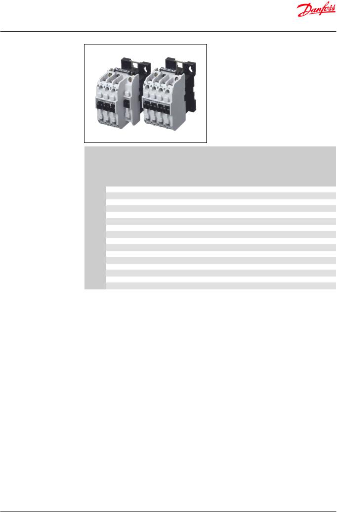
CI-TI™ Contactors and Motor Starters
Type CI 6 - 50
CI-TI™ contactors and motor starters provide trouble-free switching and maximum protection for costly motors and other electrical equipment.
The components are compact, easy to install and extremely reliable.
They are designed to meet demanding requirements, based on comprehensive application experience.
More than sixty years of manufacturing experience ensure that our contactors and motor starters stand out with regards to quality and long life.
© Danfoss | DCS (az) | 2018.10 |
IC.PD.C10.1G.02 | 1 |
Data sheet | Contactors, type CI 6 – CI 50
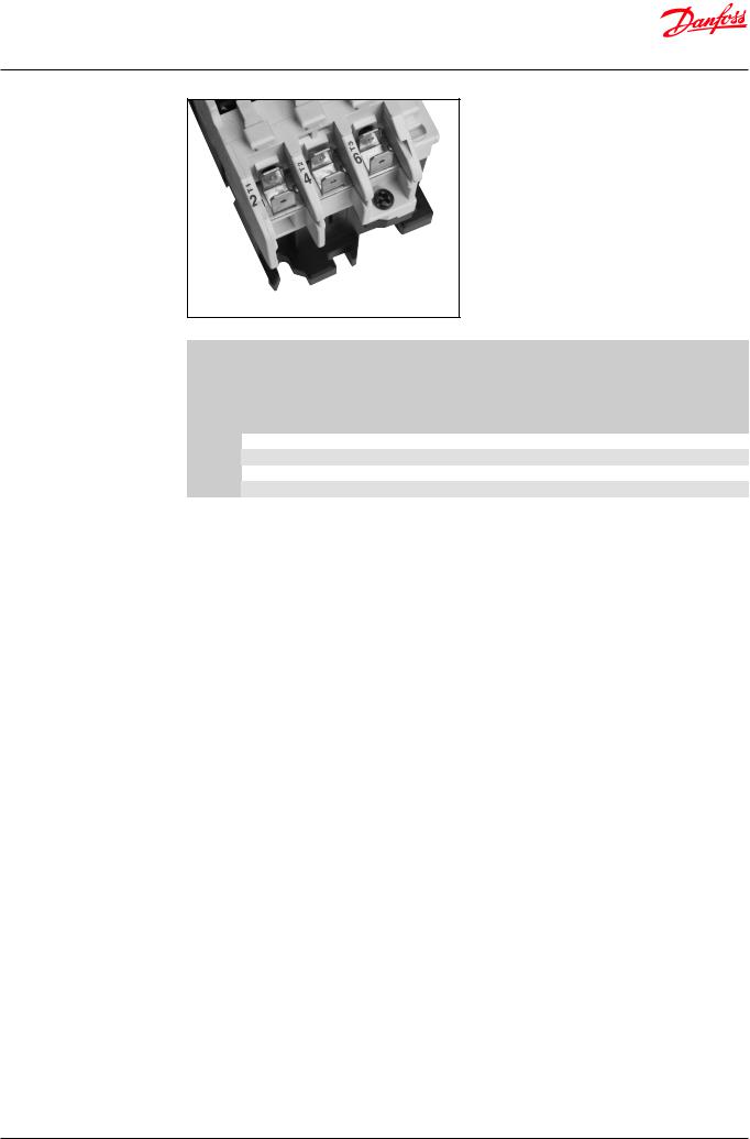
Contactors CI 6 – CI 50 for AC coil voltage (no built-in auxiliary contacts)
Danfoss contactors CI 6 – CI 50 cover the power range 2.2 – 25 kW.
CI 6 is built up as a combined contactor/control relay.
CI 9 DC – CI 30 DC and CI 9 EI – CI 30 EI are contactors for DC coil voltage within the power range 2.2 – 15 kW. The range CI 9 EI – CI 30 EI has built-in interface relay for PLC application with 24 V DC output.
Accessories include a wide selection of clip-on auxiliary contact blocks and timers, interface modules and RC links.
The CI 6 – CI 50 range also includes thermal overload relays for protection of squirrel-cage motors.
|
|
|
|
|
|
|
|
Main circuit |
|
|
Auxiliary |
|
|
|
|
|
|
AC-3 load |
|
|
Ith 4) |
Ithe 5) |
Max. |
Main |
contacts |
|
|
|
|
|
Ue |
Ue |
|
|
|
Ith 6) |
|
|
|||
|
Type |
|
|
Ie |
|
(AC-1) |
(AC-1) |
contacts |
Add-on |
Code no. 1) |
|||
|
|
220 – |
380 – |
|
|
(AC-1) |
|||||||
|
|
|
|
|
|
Open |
Encl. |
(make) |
options |
|
|||
|
|
|
240 V |
690 V |
|
|
|
Open |
|
||||
|
|
|
|
[A] |
|
[A] |
[A] |
Number |
Number |
|
|||
|
|
|
[kW] |
[kW] |
|
|
[A] |
|
|||||
|
|
|
|
|
|
|
|
|
|
|
|||
|
CI 6 2) |
|
1.5 |
2.2 |
|
6 |
|
20 |
16 |
– |
3 |
1 – 4 |
037H0015 |
|
|
1.5 |
2.2 |
|
6 |
|
20 |
16 |
– |
4 |
1 – 4 |
037H0018 |
|
|
|
|
|
|
|||||||||
|
CI 9 |
|
2.2 |
4.0 |
|
9 |
|
25 |
16 |
– |
3 |
1 – 4 |
037H0021 |
|
|
2.2 |
4.0 |
|
9 |
|
25 |
16 |
– |
4 |
1 – 4 |
037H0022 |
|
|
|
|
|
|
|||||||||
|
CI 12 |
|
3.0 |
5.5 |
|
12 |
|
25 |
20 |
– |
3 |
1 – 4 |
037H0031 |
|
|
3.0 |
5.5 |
|
12 |
|
25 |
20 |
– |
4 |
1 – 4 |
037H0032 |
|
|
|
|
|
|
|||||||||
|
CI 15 |
|
4.0 |
7.5 3) |
|
16 |
|
25 |
20 |
30 |
3 |
1 – 4 |
037H0049 |
|
|
4.0 |
7.5 3) |
|
16 |
|
25 |
20 |
30 |
4 |
1 – 4 |
037H0050 |
|
|
|
|
|
|
|||||||||
|
CI 16 |
|
4.0 |
7.5 |
|
16 |
|
40 |
25 |
45 |
3 |
1 – 4 |
037H0041 |
|
CI 20 |
|
5.5 |
10.0 |
|
20 |
|
40 |
25 |
45 |
3 |
1 – 4 |
037H0045 |
|
CI 25 |
|
5.5 |
11.0 |
|
25 |
|
40 |
25 |
45 |
3 |
1 – 4 |
037H0051 |
|
CI 30 |
|
8.5 |
15.0 |
|
32 |
|
40 |
30 |
50 |
3 |
1 – 4 |
037H0055 |
|
CI 32 |
|
8.5 |
15.0 3) |
|
32 |
|
63 |
63 |
– |
3 |
1 – 4 |
037H0061 |
|
CI 37 |
|
10.0 |
18.5 3) |
|
37 |
|
80 |
63 |
– |
3 |
1 – 4 |
037H0056 |
|
CI 45 |
|
11.0 |
22.0 3) |
|
45 |
|
80 |
80 |
90 |
3 |
1 – 4 |
037H0071 |
|
CI 50 |
|
15.0 |
25.0 3) |
|
52 |
|
80 |
80 |
90 |
3 |
1 – 4 |
037H0080 |
1) |
Suffix defining coil voltage/frequency must be added to the Danfoss code no. (see table on page 4). |
|
|
||||||||||
2) |
AC-15 operation: max. 500 VA / 6A |
|
|
|
|
|
|
|
|
||||
3) |
Ue max.: 500 V |
|
|
|
|
|
|
|
|
|
|
||
4) |
The thermal current value lth represents the maximum load at 40 °C, which corresponds to installing the contactor in air (open). |
||||||||||||
5) |
The thermal current value lthe represents the maximum load at 60 °C, which corresponds to installing the contactor inside an |
||||||||||||
|
enclosure. |
|
|
|
|
|
|
|
|
|
|
|
|
6) |
Heat-resistant leads (min. 75 °C) must be used. |
|
|
|
|
|
|
||||||
© Danfoss | DCS (az) | 2018.10 |
IC.PD.C10.1G.02 | 2 |
Data sheet | Contactors, type CI 6 – CI 50
Contactors CI 6 – CI 30 for AC coil voltage with AMP connections
The CI 6 – CI 30 contactors are also available with AMP connections in main circuits.
Coils are equipped with standard screw connections.
This version can be especially useful in the applications where contactors are installed in the large number of standardized machines (welding machines or A/C units).
|
|
|
|
|
|
Main circuit |
|
|
|
|
|
|
|
|
|
|
AC-3 load |
|
|
|
AC-1 load |
|
|
||
|
Type |
|
Ue |
Ue |
|
Ie |
|
lth 4) |
lthe 5) |
|
max. |
Code no. 1) 2) |
|
|
|
|
|
lth 6) |
|||||||
|
|
|
220 – 240 V |
380 – 690 V |
|
|
|
Open |
Encl. |
|
|
|
|
|
|
|
|
|
|
(make) |
|
||||
|
|
|
[kW] |
[kW] |
|
[A] |
|
[A] |
[A] |
|
|
|
|
|
|
|
|
|
[A] |
|
|||||
|
|
|
|
|
|
|
|
|
|
|
|
|
|
CI 6 3) |
|
1.5 |
2.2 |
|
6 |
|
20 |
16 |
|
– |
037H4016 |
|
CI 9 |
|
2.2 |
4.0 |
|
9 |
|
25 |
16 |
|
– |
037H4023 |
|
CI 12 |
|
3.0 |
5.5 |
|
12 |
|
25 |
20 |
|
– |
037H4033 |
|
CI 20 |
|
5.5 |
10.0 |
|
20 |
|
40 |
25 |
|
45 |
037H4060 |
1) |
Suffix defining coil voltage / frequency must be added to the Danfoss code no. (see table on page 4). |
|
|
|||||||||
2) |
The minimum order size is 30 pcs. for CI 6 to CI 15 and 25 pcs. for CI 16 to CI 30 in industrial packs. |
|
|
|||||||||
|
Industrial packs should be ordered as 037H40xxxx. |
|
|
|
|
|
|
|
||||
3) |
AC-15 Operation: max. 500 VA / 6A |
|
|
|
|
|
|
|
||||
4) |
The thermal current value lth represents the maximum load at 40 °C, which corresponds to installing the contactor in air (open). |
|||||||||||
5) |
The thermal current value lthe represents the maximum load at 60 °C, which corresponds to installing the contactor inside an |
|||||||||||
|
enclosure. |
|
|
|
|
|
|
|
|
|
|
|
6) |
Heat-resistant leads (min. 75 °C) must be used. |
|
|
|
|
|
|
|
||||
© Danfoss | DCS (az) | 2018.10 |
IC.PD.C10.1G.02 | 3 |

Data sheet | Contactors, type CI 6 – CI 50
AC coil voltages and coils for CI 6 – CI 30
Coil voltage *) |
Suffix no. |
Code no. |
|
24 V, 50 – 60 Hz |
13 |
037H6484 1) |
|
24 V, 50 Hz / 29 V, 60 Hz |
16 |
037H6462 |
|
42 V, 50 Hz / 50 V, 60 Hz |
17 |
037H6463 |
|
110 V, 50 Hz / 110 – 120 V, 60 Hz |
23 |
037H6487 1) |
|
208 |
– 230 V, 60 Hz |
28 |
037H6450 2) |
220 |
– 230 V, 50 Hz / 220 V, 60 Hz |
32 |
037H6488 1) |
220 |
– 240 V, 50 Hz |
31 |
037H6472 |
380 |
– 400 V, 50 Hz / 440 V, 60 Hz |
37 |
037H6478 |
415 V, 50 Hz / 500 V, 60 Hz |
38 |
037H6479 |
|
500 V, 50 Hz / 600 V, 60 Hz |
94 |
037H6481 |
|
AC coil voltages and coils for CI 32 – CI 50
|
Coil voltage *) |
|
Suffix no. |
Code no. |
|
|
24 V, 50 – 60 Hz |
|
13 |
037H6084 1) |
|
|
42 V, 50 Hz / 50 V, 60 Hz |
|
17 |
037H6063 |
|
|
110 V, 50 Hz / 110 – 120 V, 60 Hz |
|
23 |
037H6087 1) |
|
|
208 |
– 230 V, 60 Hz |
|
28 |
037H6050 2) |
|
220 |
– 230 V, 50 Hz / 220 V, 60 Hz |
|
32 |
037H6088 1) |
|
220 |
– 230 V, 50 Hz |
|
31 |
037H6072 |
|
380 |
– 400 V, 50 Hz / 440 V, 60 Hz |
|
37 |
037H6078 |
|
415 V, 50 Hz / 500 V, 60 Hz |
|
38 |
037H6079 |
|
|
500 V, 50 Hz / 600 V, 60 Hz |
|
94 |
037H6081 |
|
*) |
Standard coil voltage from -15% – 10%. |
|
|
||
1) |
Double frequency coil: voltage range ±10%. |
|
|
||
|
Continuous operation: ambient temperature max. 55 °C, non-enclosed |
|
|||
|
Intermittent operation: energized for 30 min/hour: ambient temperature max. 65 °C |
|
|||
2) |
Operating conditions and tolerances as for double frequency coils. |
|
|
||
Correct ordering of contactors
Example: CI 9 with four main contacts and 24 V, 50 Hz coil voltage.
Select one of the following two forms of ordering:
1.Danfoss code no. + Suffix no.: 037H002216
or
2.Danfoss code no. + coil voltage/frequency: 037H0022, 24 V/50 Hz
© Danfoss | DCS (az) | 2018.10 |
IC.PD.C10.1G.02 | 4 |

Data sheet | Contactors, type CI 6 – CI 50
Interface contactors |
|
Contactors CI 9 EI – CI 30 EI cover the power |
|
||
CI 9 EI – CI 30 EI (no built-in |
|
range 4 – 15 kW. |
auxiliary contacts) |
|
The operation of the coil is controlled by an |
|
|
electronic circuit. |
|
|
The range CI 9 EI – CI 30 EI has a built-in interface |
|
|
relay for PLC application with 24 V DC output. |
|
|
Accessories include a wide selection of clipon |
|
|
auxiliary contact blocks and timers. |
|
|
The CI 9 EI – CI 30 EI range also includes thermal |
|
|
overload relays for protection of squirrel-cage |
|
|
motors. |
|
|
|
|
|
|
|
|
Main circuit |
|
|
Control circuit |
|
||
|
|
|
|
AC-3 load |
|
|
AC-1 load |
Coil |
PLC 5) |
|
|
|
Type |
Ue |
|
Ue |
|
Ie |
Ith 1) |
Ithe 2) |
A1 – A2 |
B+ - B− |
Code no. |
|
220 – |
|
380 – |
|
|||||||
|
|
|
|
|
Open |
Encl. |
|
|
|
||
|
|
240 V |
|
690 V |
|
|
|
|
|
||
|
|
|
|
[A] |
[A] |
[A] |
[V] |
[V] |
|
||
|
|
[kW] |
|
[kW] |
|
|
|||||
|
|
|
|
|
|
|
|
|
|
||
|
CI 9 EI 24 |
2.2 |
|
4.0 |
|
9 |
25 |
16 |
24 DC |
24 DC |
037H801166 |
|
|
|
|
|
|
|
|
|
|
|
|
|
CI 9 EI 230 |
2.2 |
|
4.0 |
|
9 |
25 |
16 |
220 – 240 AC 4) |
24 DC |
037H806166 |
|
CI 15 EI 24 |
4.0 |
|
7.5 3) |
|
15 |
25 |
20 |
24 DC |
24 DC |
037H801366 |
|
CI 15 EI 230 |
4.0 |
|
7.5 3) |
|
15 |
25 |
20 |
220 – 240 AC 4) |
24 DC |
037H806366 |
|
CI 25 EI 24 |
5.5 |
|
11.0 |
|
25 |
40 |
25 |
24 DC |
24 DC |
037H801666 |
|
CI 25 EI 230 |
5.5 |
|
11.0 |
|
25 |
40 |
25 |
220 – 240 AC 4) |
24 DC |
037H806666 |
|
CI 30 EI 24 |
8.5 |
|
15.0 |
|
32 |
40 |
30 |
24 DC |
24 DC |
037H801766 |
|
|
|
|
|
|
|
|
|
|
|
|
|
CI 30 EI 230 |
8.5 |
|
15.0 |
|
32 |
40 |
30 |
220 – 240 AC 4) |
24 DC |
037H806766 |
1) |
The thermal current value Ith gives the maximum load at 40 °C, which corresponds to installing the contactor in air (open). |
||||||||||
2) |
The thermal current value Ithe gives the maximum load at 60 °C, corresponding to installing the contactor inside an enclosure. |
||||||||||
3) |
Ue max 500 V |
|
|
|
|
|
|
|
|
|
|
4) |
Coils are dual frequency coils |
|
|
|
|
|
|
|
|
||
5) |
Cable length from PLC to B+ and B- max. 50 m because of risks of interference. |
|
|
|
|||||||
Ordering example
CI 9 EI with 230 V AC coil and 24 V DC PLC interface:
Danfoss code number: 037H806166
(Type: CI 9 EI230)
© Danfoss | DCS (az) | 2018.10 |
IC.PD.C10.1G.02 | 5 |
Data sheet | Contactors, type CI 6 – CI 50
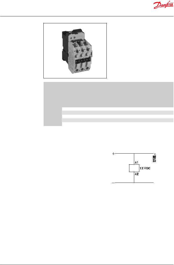
Contactors CI 9 DC – CI 30 DC (no built-in auxiliary contacts)
Contactors CI 9 DC – CI 30 DC cover the range 4 – 15 kW.
The operation of the coil is controlled by an electronic circuit.
The control voltage is 12 V DC or 24 V DC. A typical application is transport cooling.
Accessories include a wide selection of clip-on auxiliary contact blocks and timers.
The CI 9 DC – CI 30 DC range also includes thermal overload relays for protection of squirrel-cage motors.
|
|
|
|
Main circuit |
|
|
|
Control |
|
|
|
|
|
|
|
|
|
circuit |
|
||
|
|
|
|
|
|
|
|
|
||
|
|
|
AC-3 load |
|
|
AC-1 load |
Coil 4) |
|
||
|
Type |
Ue |
Ue |
|
Ith 1) |
|
Ithe 2) |
|
|
Code no. |
|
|
220 – |
380-690 |
Ie |
|
A1 – A2 |
|
|||
|
|
Open |
|
Encl. |
|
|||||
|
|
240 V |
V |
[A] |
|
[V] |
|
|||
|
|
[A] |
|
[A] |
|
|||||
|
|
[kW] |
[kW] |
|
|
|
|
|
||
|
|
|
|
|
|
|
|
|
||
|
CI 9 DC 24 |
2.2 |
4.0 |
9 |
25 |
|
16 |
24 DC |
037H807166 |
|
|
CI 15 DC 12 |
4.0 |
7.5 3) |
16 |
25 |
|
20 |
12 |
DC |
037H800366 |
|
CI 15 DC 24 |
4.0 |
7.5 3) |
16 |
25 |
|
20 |
24 |
DC |
037H807366 |
|
CI 25 DC 24 |
5.5 |
11.0 |
25 |
40 |
|
25 |
24 |
DC |
037H807666 |
|
CI 30 DC 24 |
8.5 |
15.0 |
32 |
40 |
|
30 |
24 |
DC |
037H807766 |
1) |
The thermal current value Ith gives the maximum load at 40 °C, which corresponds to installing the contactor in air (open). |
|||||||||
2) |
The thermal current value Ithe gives the maximum load at 60 °C, corresponding to installing the contactor inside an enclosure. |
|||||||||
3) |
Ue max 500 V. |
|
|
|
|
|
|
|
|
|
4) Standard coil voltage from -15% – 10%.
Ordering example
CI 15 DC with 12 V DC coil:
Danfoss code number: 037H800366
(Type: CI 15 DC 12)
© Danfoss | DCS (az) | 2018.10 |
IC.PD.C10.1G.02 | 6 |
Data sheet | Contactors, type CI 6 – CI 50
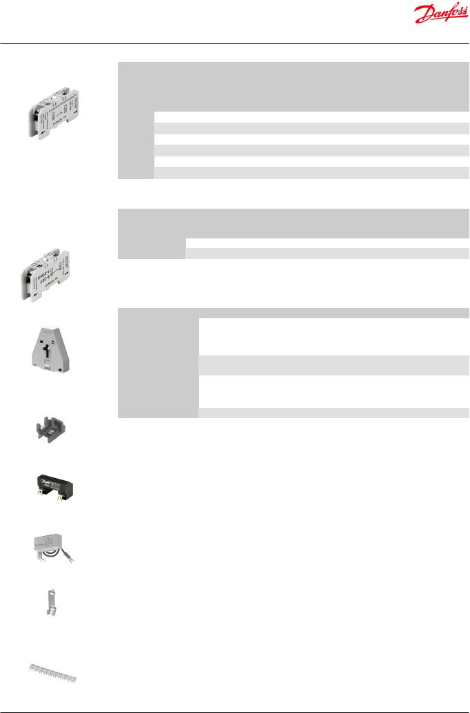
Auxiliary contact blocks CB for CI 6 – CI 50
Auxiliary contact block CBwith gold-plated contacts (PLC-compatible)
Accessories for contactors CI 6 – CI 50
Mech. interlock
CI 9 DC – CI 30 DC
CI 9 EI – CI 30 EI
Mech. interlock
CI 32 – CI 50
|
|
|
|
|
|
|
Load |
|
|
|
|
|
|
|
|
|
|
|
Ie |
Ith 1) |
|
Ithe 2) |
|
|
|
|
|
|
|
|
Type |
Contact function |
(AC - 15) |
(AC-1) |
|
(AC-1) |
|
Ue |
|
Colour code |
Code no. |
|||
|
|
|
|
|
|
Open |
|
Enc. |
|
|
|
|
|
|
|
|
|
|
|
|
|
|
|
|
|
|
|
||
|
|
|
|
[A] |
[A] |
|
[V] |
|
|
|
|
|
|
|
|
|
|
|
|
|
|
|
|
|
|
|
|
|
|
|
CB-S |
start |
6 |
|
10 |
|
10 |
500 |
|
green |
037H0110 |
|||
|
|
|
|
|
|
|
|
|
|
|
|
|
|
|
|
CB-I |
start pulse 3) |
6 |
|
10 |
|
10 |
500 |
|
green |
037H0117 |
|||
|
CB-NO |
make |
6 |
|
10 |
|
10 |
500 |
|
green |
037H0111 |
|||
|
|
|
|
|
|
|
|
|
|
|
|
|
|
|
|
CB-NC |
break |
6 |
|
10 |
|
10 |
500 |
|
red |
037H0112 |
|||
|
|
|
|
|
|
|
|
|
|
|
|
|
|
|
|
CB-EM |
early make |
6 |
|
10 |
|
10 |
500 |
|
white |
037H0113 |
|||
|
|
|
|
|
|
|
|
|
|
|
|
|
|
|
|
CB-LB |
late break |
6 |
|
10 |
|
10 |
500 |
|
blue |
037H0114 |
|||
|
|
|
|
|
|
|
|
|
|
|
|
|
||
1) |
The thermal current value Ith gives the maximal load at 40 °C, which corresponds to installing the contactor in air (open). |
|||||||||||||
2) |
The thermal current value Ithe gives the maximal load at 60 °C, corresponding installing the contactor inside an enclosure. |
|||||||||||||
3) |
Without self-holding function. |
|
|
|
|
|
|
|
|
|
|
|
||
|
|
|
|
|
|
|
Load |
|
|
|
|
|
|
|
|
Type |
|
Contact function |
|
Ie |
|
Ue |
|
Colour code |
|
Code no. |
|||
|
|
|
|
|
|
mA |
|
V |
|
|
|
|
|
|
|
CB-NO |
|
make |
|
|
1 – 30 |
|
5 – 30 |
|
|
white |
|
037H0121 |
|
|
CB-NC |
|
break |
|
|
1 – 30 |
|
5 – 30 |
|
|
blue |
|
037H0122 |
|
CB auxiliary contact blocks are force-actuated when |
In the standard auxiliary contact CB - the silver tips |
|||
mounted on CI 6 – CI 30 and can therefore form part of |
on the moreable contact is cross stamped and PLC - |
|||
safety switching. |
|
compatible. |
|
|
|
|
Min. load 24 V, 10 mA. |
|
|
|
|
|
|
|
Description |
Comments |
|
Code no. |
|
Mech. interlock |
|
|
|
|
for CI 6 – CI 30 |
Mech. interlock can be established between pairs (1-off ). |
037H009166 |
||
CI 9 DC – CI 30 DC, |
||||
|
|
|
||
CI 9 EI – CI 30 EI |
|
|
|
|
Mech. interlock |
Mech. interlock can be established between |
037H010666 |
||
for CI 32 – CI 50 |
||||
|
|
|
||
RC Element |
Reduces overvoltage on de-energization of coils |
|
||
Type RC 250 (110 – 250 V, 50/60 Hz) |
|
037H0076 |
||
for CI 6 – CI 30 |
|
|||
|
|
|
||
Type RC 415 (380 – 415 V, 50/60 Hz) |
|
037H0077 |
||
|
|
|||
|
|
|
||
Rating plate for CI 6 - 50 |
Rating plate, can be mounted in auxiliary contact space (10-off ) |
037H010166 |
||
RC Element
CI 6 – CI 30
RCB-
Rating plate
CI 6 – CI 50
Clip-on markers
CI 6 – CI 50 and CB-
© Danfoss | DCS (az) | 2018.10 |
IC.PD.C10.1G.02 | 7 |

Data sheet | Contactors, type CI 6 – CI 50
ON-delay clip-on timers for AC control voltage 50 / 60 Hz
ETB
ETB electronic clip-on timers are for use with Danfoss contactors to delay contactor close and open.
The clip-on timers can be clipped direct onto contactors CI 6 – CI 50 and occupy as little space as one auxiliary contact.
Where separate mounting at the side of contactors is required, a DIN rail mounting base is available.
Type |
Time range |
Voltage range |
Code no. |
|||
[V] |
||||||
|
|
|
|
|||
|
0.5 – 20 s |
24 |
– 65 |
047H0170 |
||
|
4 |
– 160 s |
24 |
– 65 |
047H0171 |
|
ETB |
0.5 – 20 s |
110 |
– 240 |
047H0173 |
||
|
4 |
– 160 s |
110 |
– 240 |
047H0174 |
|
|
0.5 |
– 20 min |
110 |
– 240 |
047H0175 |
|
OFF-delay clip-on timers for AC control voltage 50 / 60 Hz
Accessory for ETB
Type |
Time range |
Voltage range |
Code no. |
|||
[V] |
||||||
|
|
|
|
|||
|
0.5 – 20 s |
24 |
– 65 |
047H0180 |
||
|
|
|
|
|
|
|
|
4 |
– 160 s |
24 |
– 65 |
047H0181 |
|
ETB |
0.5 |
– 20 min |
24 |
– 65 |
047H0182 |
|
0.5 – 20 s |
110 |
– 240 |
047H0183 |
|||
|
||||||
|
4 |
– 160 s |
110 |
– 240 |
047H0184 |
|
|
0.5 |
– 20 min |
110 |
– 240 |
047H0185 |
|
|
|
|
|
|
|
|
Description |
Comments |
|
|
Code no. |
||
|
|
|
|
|
||
DIN rail base for ETB |
For separate mounting of clip-on timers ETB |
|
047H016466 |
|||
© Danfoss | DCS (az) | 2018.10 |
IC.PD.C10.1G.02 | 8 |

Data sheet | Contactors, type CI 6 – CI 50
Thermal overload relays |
|
|
|
|
|
|
|
Thermal overload relays TI 16C, TI 25C and |
|||||||
TI 16C, TI 25C, TI 30C for |
|
|
|
|
|
|
|
TI 30C are used with contactors CI 6 – CI 30 to give |
|||||||
contactors CI 6 – CI 30 |
|
|
|
|
|
|
|
protection of squirrel-cage motors of 0.09 kW to |
|||||||
|
|
|
|
|
|
|
|
15 kW. |
|
|
|
|
|
|
|
|
|
|
|
|
|
|
|
The relays have single-phase protection, i.e. |
|||||||
|
|
|
|
|
|
|
|
accelerated release if phase drop-out occurs. |
|||||||
|
|
|
|
|
|
|
|
This is particularly important for motors with |
|||||||
|
|
|
|
|
|
|
|
delta-connected windings. |
|
|
|
||||
|
|
|
|
|
|
|
|
Other features of TI 16C / 25C / 30C: |
|
||||||
|
|
|
|
|
|
|
|
• stop/reset button |
|
|
|
||||
|
|
|
|
|
|
|
|
• manual/automatic reset |
|
|
|
||||
|
|
|
|
|
|
|
|
• test button |
|
|
|
|
|
||
|
|
|
|
|
|
|
|
• double scale for direct start or Y/D start |
|||||||
|
|
|
|
|
|
|
|
• galvanically isolated signal contact |
|
||||||
|
|
|
|
|
|
|
|
|
|
|
|
|
|
|
|
|
|
|
|
Range |
|
|
Max. fuse 1) |
|
|
HRC 2) |
|
|
|||
|
|
Type |
Motor- |
|
Y/D- |
gl, gL, gG |
|
BS 88, type T |
|
II |
|
Code no. |
|||
|
|
starter |
|
starter |
Type 1 |
Type 2 |
|
Type 1 |
Type 2 |
|
|
|
|||
|
|
|
|
|
|
|
|
|
|||||||
|
|
|
[A] |
|
[A] |
[A] |
|
[A] |
|
[A] |
[A] |
|
[A] |
|
|
|
|
|
0.13 – 0.20 |
– |
25 |
|
– |
|
32 |
– |
|
1 |
|
047H0200 |
|
|
|
|
0.19 – 0.29 |
– |
25 |
|
– |
|
32 |
2 |
|
1 |
|
047H0201 |
|
|
|
|
0.27 – 0.42 |
– |
25 |
2 |
|
32 |
2 |
|
1 |
|
047H0202 |
||
|
|
|
0.4 – 0.62 |
|
– |
25 |
2 |
|
32 |
4 |
|
1 |
|
047H0203 |
|
|
|
|
0.6 – 0.92 |
|
– |
25 |
4 |
|
32 |
6 |
|
3 |
|
047H0204 |
|
|
|
|
0.85 – 1.3 |
|
– |
25 |
4 |
|
32 |
6 |
|
3 |
|
047H0205 |
|
|
|
TI 16C |
1.2 – 1.9 |
|
– |
25 |
6 |
|
32 |
10 |
|
6 |
|
047H0206 |
|
|
|
|
1.8 – 2.8 |
|
3.2 – 4.8 |
25 |
6 |
|
32 |
10 |
|
15 |
|
047H0207 |
|
|
|
|
2.7 – 4.2 |
|
4.7 – 7.3 |
25 |
16 |
|
32 |
20 |
|
15 |
|
047H0208 |
|
|
|
|
4.0 – 6.2 |
|
6.9 – 10.7 |
35 |
20 |
|
40 |
25 |
|
15 |
|
047H0209 |
|
|
|
|
6.0 – 9.2 |
|
10 – 16 |
50 |
20 |
|
50 |
25 |
|
35 |
|
047H0210 |
|
|
|
|
8.0 – 12 |
|
13 – 20.8 |
63 |
25 |
|
63 |
32 |
|
35 |
|
047H0211 |
|
|
|
|
11 – 16 |
|
19 – 27 |
80 |
25 |
|
80 |
32 |
|
50 |
|
047H0212 |
|
|
|
TI 25C |
15 – 20 |
|
26 – 35 |
80 |
35 3) |
|
80 |
40 |
|
60 |
|
047H0213 |
|
|
|
19 – 25 |
|
33 – 43 |
80 |
63 |
|
80 |
63 |
|
60 |
|
047H0214 |
||
|
|
|
|
|
|
|
|||||||||
|
|
TI 30C |
24 – 32 |
|
41 – 55 |
80 |
63 |
|
80 |
63 |
|
60 |
|
047H0215 |
|
1) |
To IEC 947-4 coordination types 1 and 2: |
|
|
|
|
|
|
|
|
|
|
||||
|
|
Coordination type 1: |
Any type of damage to the motor starter is permissible. If the motor starter is in an enclosure, no external |
||||||||||||
|
|
|
|
damage to the enclosure is permissible. After a short-circuit the thermal overload relay shall be partially or |
|||||||||||
|
|
|
|
wholly replaced. |
|
|
|
|
|
|
|
|
|
|
|
|
|
Coordination type 2: |
No damage to the motor starter is permissible, but slight contact burning and welding is permissible. |
||||||||||||
2) |
In accordance with HRC form II, TI 16C, TI 25C and TI 30C are suitable for operation in Canada and the USA. |
|
|
|
|||||||||||
3) |
50 A in Norway. |
|
|
|
|
|
|
|
|
|
|
|
|
||
Selection of thermal overload relay
The selection of a thermal overload relay must be based on the motor full load current and the method of starting:
-With direct start the range for motor starter is used.
-With star-delta start the range for Y/D starter is used.
Example:
Full load current: 16 A
-With direct start, the suitable motor starter range is 11 – 16 A, i.e. thermal overload relay
047H0212.
-With star-delta start, the suitable Y/D starter range is 10 – 16 A, i.e. thermal overload relay
047H0210.
The range 13 – 20.8 A could also be used, but thermal overload relay 047H0211 will not release as quickly if one phase drops out.
© Danfoss | DCS (az) | 2018.10 |
IC.PD.C10.1G.02 | 9 |
 Loading...