


Installation Guide
AMV (-H) 610, 613, 633
|
|
|
|
|
|
|
|
|
|
|
|
|
|
|
|
|
|
|
|
|
|
|
|
|
|
|
|
|
|
|
|
|
|
|
|
|
|
|
|
|
|
|
|
|
|
|
|
|
|
|
|
|
|
|
|
|
|
|
|
|
|
|
|
|
|
|
|
|
|
|
|
|
|
|
|
|
|
|
|
|
|
|
|
|
|
|
|
|
|
|
|
|
|
|
|
|
|
|
|
|
|
|
|
|
|
|
|
|
|
|
|
|
|
|
|
|
|
|
|
|
|
|
|
|
|
|
|
|
|
|
|
|
|
|
|
|
|
|
|
|
|
|
|
|
|
|
|
|
|
|
|
|
|
|
|
|
|
|
|
|
|
|
|
|
|
|
|
|
|
|
|
|
|
|
|
|
|
|
|
|
|
|
|
|
|
|
|
|
|
|
|
|
|
|
|
|
|
|
|
|
|
|
|
|
|
|
|
|
|
|
|
|
|
|
|
|
|
|
|
|
|
|
|
|
|
|
|
|
|
|
|
|
|
|
|
|
|
|
|
|
|
|
|
|
|
|
|
|
|
|
|
|
|
|
|
|
|
|
|
|
|
|
|
|
|
|
|
|
|
|
|
|
|
|
|
|
|
|
|
|
|
|
|
|
|
|
|
|
|
|
|
|
|
|
|
|
|
|
|
|
|
|
|
|
|
|
|
|
|
|
|
|
|
|
|
|
|
|
|
|
|
|
|
|
|
|
|
|
|
|
|
|
|
|
|
|
|
|
|
|
|
|
|
|
|
|
|
|
|
|
|
|
|
|
|
|
|
|
|
|
|
|
|
|
|
|
|
|
|
|
|
|
|
|
|
|
|
|
|
|
|
|
|
|
|
|
|
|
|
|
|
|
|
|
|
|
|
|
|
|
|
|
|
|
|
|
|
|
|
|
|
|
|
|
|
|
|
|
|
|
|
|
|
|
|
|
|
|
|
|
|
|
|
|
|
|
|
|
|
|
|
|
|
|
|
|
|
|
|
|
|
|
|
|
|
|
|
|
|
|
|
|
|
|
|
|
|
|
|
|
|
|
|
|
|
|
|
|
|
|
|
|
|
|
|
|
|
|
|
|
|
|
|
|
|
|
|
|
|
|
|
|
|
|
|
|
|
|
|
|
|
|
|
|
|
|
|
|
|
|
|
|
|
|
|
|
|
|
|
|
|
|
|
|
|
|
|
|
|
|
|
|
|
|
|
|
|
|
|
|
|
|
|
|
|
|
|
|
|
|
|
|
|
|
|
|
|
|
|
|
|
|
|
|
|
|
|
|
|
|
|
|
|
|
|
|
|
|
|
|
|
VFG 2 |
|
VFU 2 |
|
VFGS 2 |
|
AFQM |
|||||||||||||||||||||
|
|
|
VFG 21 |
|
|
|
|
|
|
|
|
|
|
|
|
|
|
|
|
|
|
|
|
|
|
|||||
|
|
|
VFG 25 |
|
|
|
|
|
|
|
|
|
|
|
|
|
|
|
|
|
|
|
|
|
|
|||||
ENGLISH |
Electrical Actuator AMV (-H) 610, 613, 633 |
www.danfoss.com |
Page 7 |
|
|
|
|
|
|
|
|
DEUTSCH |
Elektrischer Stellantrieb AMV (-H) 610, 613, 633 |
www.danfoss.de |
Seite 10 |
|
|
|
|
|
|
|
|
FRANÇAIS |
Servomoteur électrique AMV (-H) 610, 613, 633 |
www.danfoss.com |
Page 13 |
|
|
|
|
|
|
|
|
POLSKI |
Siłownik elektryczny AMV (-H) 610, 613, 633 |
www.danfoss.pl |
Strona 16 |
|
|
|
|
|
|
|
|
SRPSKI |
Elektro pogon AMV (-H) 610, 613, 633 |
www.grejanje.danfoss.com |
Strana 19 |
|
|
|
|
|
|
|
|
|
AMV (-H) 610, 613, 633 |
www.danfoss.com |
22 |
|
|
|
|
|
|
|
|
РУССКИЙ |
Электропривод AMV (-H) 610, 613, 633 |
www.danfoss.ru |
Страница 25 |
|
|
|
|
Danfoss Heating |
VI.AA.T2.3K |
DH-SMT/SI |
1 |
Installation Guide |
AMV (-H) 610, 613, 633 |
|
|


|
|
|
|
L |
|
|
|
|
L |
|
|
|
|
|
|
|
|
|
|
|
|
|
|
|
|
|
|
|
|
|
|
|
|
|
|
|
|
|
|
|
|
|
|
|
<![if ! IE]> <![endif]>B |
|
|
|
|
<![if ! IE]> <![endif]>B |
|
|
|
|
|
|
|
|
|
|
|
|
|
| <![if ! IE]> <![endif]> |
|
|
|
|
|
|
|
|
|
|
|
|
|
|
|
|
|
|
|
|
|
|
<![if ! IE]> <![endif]>1 |
|
|
|
|
|
<![if ! IE]> <![endif]>C |
|
|
|
|
|
|
|
|
|
|
|
|
|
|
|
|
|
|
|
|
|
|
|
|
|
<![if ! IE]> <![endif]>B |
|
|
|
|
|
|
|
|
VFG, VFGS DN 15-125 |
|
VFG DN 150-250 |
|
|
|
|
|
|
|
|
|
L |
|||
|
|
|
|
|
|
|
|
|
|
|
|
|
|
|
|
|
|
|
|
|
|
|
VFG, VFGS DN 150-250 |
|
|
|
VFU DN 15-125 |
||||
|
|
|
|
|
|
|
with body extension |
|
|
|
|
|
|||
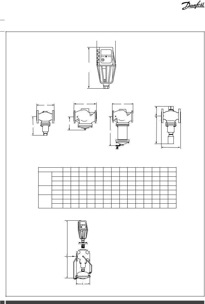
Valves |
|
DN |
15 |
20 |
25 |
32 |
40 |
50 |
65 |
80 |
100 |
125 |
150 |
200 |
250 |
|
L |
mm |
130 |
250 |
260 |
280 |
200 |
230 |
290 |
310 |
350 |
400 |
480 |
600 |
730 |
VFG(S) |
B |
mm |
212 |
212 |
238 |
238 |
240 |
240 |
275 |
275 |
380 |
380 |
326 |
354 |
404 |
|
Weight |
kg |
7 |
9 |
10 |
13 |
17 |
22 |
33 |
41 |
60 |
79 |
85 |
145 |
228 |
VFG(S) |
B1 |
mm |
- |
- |
- |
- |
- |
- |
- |
- |
- |
- |
630 |
855 |
1205 |
|
|
|
|
|
|
|
|
|
|
|
|
|
|
|
|
Tmax 300 |
Weight |
kg |
- |
- |
- |
- |
- |
- |
- |
- |
- |
- |
140 |
210 |
300 |
|
B |
mm |
95 |
95 |
106 |
106 |
123 |
123 |
135 |
135 |
165 |
165 |
- |
- |
- |
VFU 2 |
C |
mm |
311 |
311 |
337 |
337 |
339 |
339 |
374 |
374 |
479 |
479 |
- |
- |
- |
|
Weight |
kg |
7 |
9 |
10 |
13 |
17 |
22 |
33 |
41 |
60 |
79 |
- |
- |
- |
<![endif]>A
|
|
|
|
|
|
|
|
|
|
|
|
|
|
|
DN |
|
65 |
80 |
100 |
125 |
|
|
|
|
|
|
|
|
|
|
|
|
|
|
|
L |
(mm) |
290 |
310 |
350 |
400 |
|
|
|
|
|
|
|
|
|
|
|
|
|
|
|
|
|
|
|
|
|
|
|
|
|
|
|
|
|
|
|
|
|
|
|
|
A |
600 |
610 |
- |
- |
|
|
|
|
|
|
|
|
|
|
|
|
|
|
|
|
||||||
|
|
|
|
|
|
|
|
|
|
|
|
|
|
|
||||||
|
|
|
|
|
|
|
|
|
|
|
|
|
|
|
B |
|
425 |
425 |
530 |
530 |
|
|
|
|
|
|
|
|
|
|
|
|
|
|
|
|
|||||
|
|
|
|
|
|
|
|
|
|
|
|
|
|
|
|
|
|
|
|
|
|
|
|
|
|
|
|
|
|
|
|
|
|
|
|
|
|
|
|
|
|
|
|
|
|
|
|
|
|
|
|
|
|
|
|
|
|
|
|
|
|
|
<![endif]>B
AFQM (DN 65-125) + AMV (-H) 6xx
2 |
DH-SMT/SI |
VI.AA.T2.3K |
Danfoss Heating |
 610, AMV (-H) 613, AMV (-H) 633 Operating guide")
Installation Guide |
AMV (-H) 610, 613, 633 |
|
|
|
|
|||
|
|
|
|
|
|
|
|
|
|
|
VFG 2 |
VFG 2 |
|
|
|
|
|
|
Valve type |
VFG 21 |
VFU 2 |
VFGS 2 |
|
AFQM |
|
|
|
VFG 21 |
|
|
|||||
|
|
VFG 25 |
|
|
|
|
|
|
|
|
|
|
|
|
|
|
|
|
DN |
15-125 |
150-250 |
15-125 |
15-125 |
150-250 |
65-125 |
|
|
PN |
|
|
16, 25, 40 |
|
|
25 |
|
|
Medium |
|
Hot water |
|
Steam |
|
Hot water |
|
|
|
VFG 2: 200 |
|
|
|
|
|
|
|
Tmax Medium |
VFG 25: 200 |
140 |
200 |
350 |
300 |
150 |
|
|
|
VFG 21: 150 |
|
|
|
|
|
|
|
AFQM |
|
AFQM |
|
VFGS 2 |
|
|
|
|
VFU 2 |
|
|
VFU 2 |
|
|
|
|
|
VFG 2 (21), (25) |
|
VFG 2 (21), (25) |
|
|
|
|
|
|
|
|
|
|
|
|
|
|
|
|
|
|
|
|
|
DN 150-250 |
|
|
|
|
|
|
|
|
|
|
|
|
|
|
|
|
|
|
|
|
|
|
|
|
|
|
DN 150-250 |
|
|
|
|
|
|
AFQM, AFQM 6 |
|
|
|
Danfoss Heating |
|
|
VI.AA.T2.3K |
|
|
DH-SMT/SI |
3 |
|
|
Installation Guide |
AMV (-H) 610, 613, 633 |
|
|||
|
|
|
|
|
|
|
|
|
|
|
|
|
|
|
OPEN |
|
|
|
|
|
|
|
|
|
|
|
|
|
STOP |
|
|
|
|
|
|
AUTO |
|
|
|
|
|
|
STOP |
|
|
|
|
|
|
CLOSE |
|
|
|
|
|
|
|
|
|
|
|
|
|
|
|
|
|
|
|
|
|
|
|
|
|
|
|
|
|
|
|
|
|
|
|
|
|
|
|
|
|
|
|
|
|
|
|
|
|
|
|
|
|
|
|
|
|
|
|
|
|
|
|
|
|
|
|
|
|
|
Ventilhub |
|
20 |
– mA |
|
|
|
|
|
|
|
|
|
|
0/4 - 20 mA |
|
19 |
+ mA |
|
|
|
|
|
18 |
|
|
|
|
|
|
17 |
PE |
|
|
|
Externe Regelung |
16 |
Ö nen |
Handschalter |
|
|
|
|
Schließen |
|
||
|
|
pot. freie Kontakte |
|
15 |
|
|
|
|
|
|
14 |
L |
|
|
|
|
|
13 |
|
|
|
|
Kontakte für Stellung “OPEN” beschränken |
12 |
|
|
|
|
|
|
|
11 |
|
Ö nen |
|
|
|
|
|
|
|
|
|
|
|
10 |
|
|
|
|
Kontakte für Stellung “CLOSE” beschränken |
9 |
|
|
|
|
|
|
|
8 |
|
Schließen |
|
|
|
|
|
|
Open (Ö nen) |
|
|
|
|
7 |
L |
Stop |
|
|
Sicherheitsdruckbegrenzer |
Zworka |
|
Auto |
|
|
|
|
|
|
Stop |
|
|
|
|
|
6 |
|
Close (Schließen) |
|
|
|
|
5 |
|
|
|
|
Sicherheitstemperaturbegrenzer |
Zworka |
|
|
|
|
|
|
|
L |
|
|
|
|
|
|
4 |
|
|
|
|
|
|
3 |
PE |
|
|
|
Spannungsversorgung |
2 |
N |
|
|
|
|
L/N/PE ~ 230 |
V/ 50 Hz |
1 |
L |
|
|
|
|
|
|
||
4 |
DH-SMT/SI |
|
|
VI.AA.T2.3K |
Danfoss Heating |
|
Installation Guide |
AMV (-H) 610, 613, 633 |
|
||
VFG.., AFQM |
|
|
|
|
|
OPEN |
|
|
|
|
|
|
|
|
|
STOP |
|
||
|
|
|
|
|
|
AUTO |
|
|
0 - 2 V |
|
STOP |
|
|
|
|
|
|
|
|
|
CLOSE |
|
|
|
|
|
|||
|
|
|
|
|
|
|
|
|
0 V |
|
OPEN |
OPEN |
|
|
|
|
STOP |
STOP |
|
|
|
|
AUTO |
AUTO |
|
|
|
|
STOP |
STOP |
|
|
|
|
CLOSE |
CLOSE |
|
|
|
|
|
0 - 2 V |
|||
|
|
|
|
||
|
|
|
|
|
|
|
|
|
|
|
|
|
|
|
|
|
|
|
|
|
|
2 V |
OPEN |
|
|
|
|
|
|
|
|
|
|
|
STOP |
|
|
|
|
|
AUTO |
|
|
|
|
STOP |
|
|
|
|
|
|
|
|
|
|
|
|
CLOSE |
VFU
|
OPEN |
|
|
STOP |
|
|
AUTO |
|
|
STOP |
|
CLOSE |
||
|
|
|
|
|
|
|
|
|
|
|
0 - 2 V |
|
|
|
|
|
|
|
|
||
|
|
 0 V
0 V
OPEN |
|
OPEN |
|
STOP |
|
STOP |
|
AUTO |
|
AUTO |
|
STOP |
|
STOP |
|
CLOSE |
|
CLOSE |
|


|
|
|
|
|
OPEN
STOP
AUTO
STOP
CLOSE
Danfoss Heating |
VI.AA.T2.3K |
DH-SMT/SI |
5 |
|
Installation Guide |
AMV (-H) 610, 613, 633 |
|
|
||
|
|
|
|
|
|
|
|
VFG.., AFQM |
|
VFU 2 |
|
|
|
|
|
|
<![if ! IE]> <![endif]>h |
|
<![if ! IE]> <![endif]>h |
|
|
|
|
|
|
||
|
|
|
|
|
|
|
|
OPEN |
|
|
OPEN |
|
|
|
STOP |
|
|
STOP |
|
|
|
AUTO |
|
AUTO |
|
|
|
|
|
|
|
|
||
|
STOP |
|
|
STOP |
|
|
|
CLOSE |
|
|
CLOSE |
|
|
|
|
|
|
|
|
|
|
|
|
|
|
|
|
|
|
|
VFG.., AFQ |
VFU 2 |
|
|
|
|
|
|
OPEN |
OPEN |
|
|
|
|
|
|
|
|
|
OPEN |
|
STOP |
STOP |
|
|
|
AUTO |
|
||||
|
STOP |
|
|
AUTO |
|
|
|
|
|
|
|
||
|
|
|
STOP |
STOP |
|
|
|
AUTO |
|
|
|
||
|
|
|
|
|
||
|
|
|
CLOSE |
CLOSE |
|
|
|
STOP |
|
|
|
||
|
|
|
|
|
||
|
|
|
|
|
|
|
|
CLOSE |
|
|
|
|
|
|
|
|
|
|
||
|
|
|
VFG.., AFQ |
VFU 2 |
|
|
|
|
|
|
|
|
|
|
OPEN |
|
|
|
|
|
|
STOP |
|
|
|
|
|
|
AUTO |
|
|
|
|
|
|
STOP |
|
|
|
|
|
|
|
|
|
|
|
|
|
CLOSE |
|
|
|
|
|
|
|
|
|
|
|
|
|
|
|
|
|
VFG.., AFQ |
VFU 2 |
|
|
|
|
|
|
|
|
|
|
|
|
|
|
|
|
|
|
|
|
|
|
|
|
|
VFG.., AFQ |
VFU 2 |
|
6 |
DH-SMT/SI |
|
|
VI.AA.T2.3K |
|
Danfoss Heating |

|
|
|
|
|
|
Installation Guide |
AMV (-H) 610, 613, 633 |
|
|
|
|
|
|
|
|
|
|
English
Safety Notes
Prior to assembly and commissioning to avoid injury of persons and damages of the devices, it is absolutely necessary to carefully read and observe these instructions.
Necessary assembly, start-up, and maintenance work must be performed only by qualified, trained and authorized personnel.
Prior to assembly and maintenance work on the controller, the system must be:
-depressurized,
-cooled down,
-emptied and
-cleaned.
Please comply with the instructions of the system manufacturer or system operator.
Do not remove the cover before the power supply is fully switched off.
Disposal instruction
This product should be dismantled and its components sorted, if
possible, in various groups before recycling or disposal.
Always follow the local disposal regulations.
Definition of Application
The electrical actuator is used in connection with the following valves: VFG 2(21), VFG 25, VFU 2, VFGS 2, AFQM
Fields of application are the temperature control of water, water-glycol mixtures and steam for heating, district heating and cooling systems.
Mounting
Permissible Installation Positions
- DN 15-50 (T max < 120oC): |
|
valve type AFQM |
- |
-DN 15-80 (T max < 120oC):
valve types VFG 2, VFG 21, VFG 25, VFU 2
- DN 15-250 (T max > 120 oC)
all allowed valve types |
|
- DN 65-125 (T max < 120oC): |
|
valve type AFQM |
- |
-DN 100-250 (T max < 120oC): valve types VFG 2, VFG 21, VFU 2
DN 15-250:
valve type VFGS 2 (steam).
Valve Installation
1.Install strainer in front of valve.
2.Rinse system before installing valve.
3.Observe flow direction on the valve body
Flanges in the pipeline system must be in parallel direction, the sealing surfaces must be clean and undamaged.
4.Install valve.
5.Tighten screws crosswise in 3 steps up to the maximum torque.
Actuator and Valve Installation
Before mounting :
1.Carry out the electrical connection procedure acc. to the next paragraph
2.turn the rotary switch to the position “OPEN” to run the actuator stemcompletely back
Valves DN 150 - 250
For these valves the stem of the actuator must be screwed into the valve stem.
Overview Actuators AMV(-H) 6..
|
610/30 |
613/33 |
(-H )613/33 |
|
|
|
|
|
|
Safety |
- |
+ |
+ |
|
function |
||||
|
|
|
||
Mechanical |
- |
- |
+ |
|
adjustment |
||||
|
|
|
Dimensions, Weights
Flanges:
Connection dimensions acc. to EN 1092-2
Valve Types for AMV(-H) 6..
The electrical actuator AMV(-H) 6.. can be mounted on the following valves, see .
Observe the Operating Instructions attached to the valves.
Valves DN 15 - 125
1.Perform electrical connection, see Electrical Connection Diagrams .
2.Turn rotary switch to position “OPEN”, this will retract the actuator stem completely.
3.Turn rotary switch to position “STOP”
4.Place actuator on the valve and align.
5.Tighten union nut torque 100 Nm
Insulation
Disassembly of Valve, Actuator
 Danger
Danger of injury by steam or hot water!
Valve without actuator is open , sealing is in the actuator.
It is absolutely necessary to depressurize system prior to any work.
Carry out disassembly in reverse order as assembly.
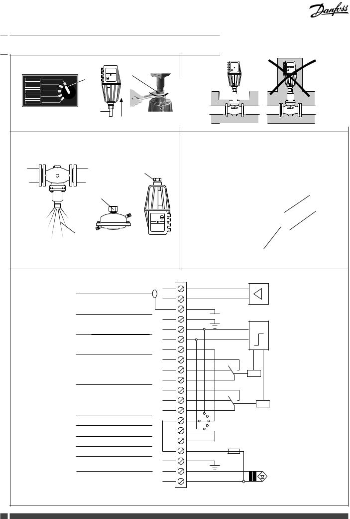
Electrical Connection
 HIGH VOLTAGE !
Danger of injury and life in case of improper handling!
Switch off power supply prior to connecting lines.
The electrical connection must only be performed by an expert electrician.
To access electrical panel remove the cover first.
Removing the cover
1.Loosen slotted screw at the rotary switch , remove rotary switch.
2.Unscrew screw and remove cover .
Connections
When cover is removed connect lines in accordance with connection diagram, see :
Connection for:
STB - Safety Temperature Limiter STW - Safety Temperature Monitor SDB - Safety Pressure Limiter
Prior to remounting the cover, carry out settings at the actuator, see next section.
Prior to connection it is absolutely necessry to remove the jumper - only types AMV (-H) 613, 633 with safety return function.
Final Position Settings
After having mounted the valves and the actuator, the final positions “Valve OPEN” and “Valve CLOSED” must be set.
Pre-conditions for the settings:
•the actuator is mounted on the valve
•the electrical connection is completed.
Danfoss Heating |
VI.AA.T2.3K |
DH-SMT/SI |
7 |
|
|
|
|
Installation Guide |
AMV (-H) 610, 613, 633 |
|
|
|
|
|
|
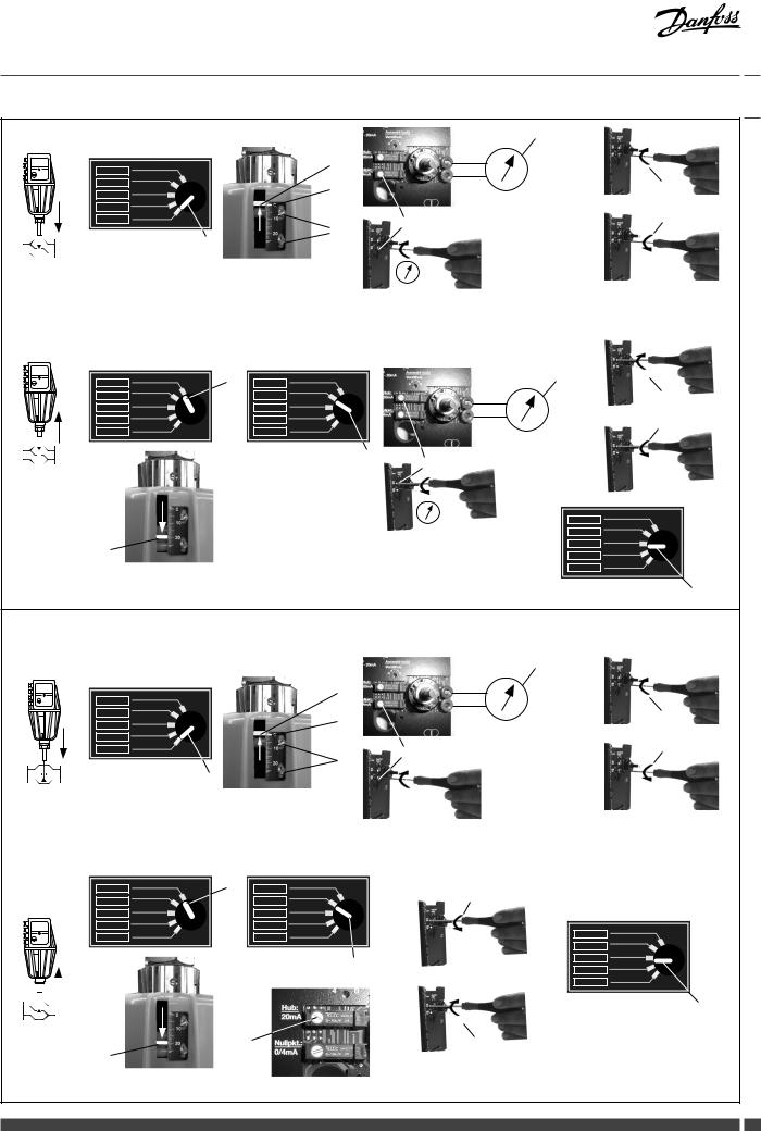
Valves VFG .., AFQM
Setting the final position “Valve CLOSED”
Procedure:
1.Set rotary switch to position “CLOSE” . The stroke indicator must move in
the direction of the arrow up to its stop. Valve is completely closed
2.Align stroke indicator:
•Loosen screws
•Align display to 0
•Tighten screws
3.Dismount the cover see
4.If available, connect measuring device to sockets
If no measuring device is available, continue with step 6.
5.Turn pot with a screwdriver until the
measuring device shows 0 V
The final position “Valve CLOSED” is set.
Adjustment without measuring device
6.Turn pot with a screwdriver by about 10 rotations to the right
7.Afterwards, turn pot to the left until the relay switch is audible, then stop immediately
If the pot has been turned too far, turn it again to the right and afterwards
again to the left
The final position “Valve CLOSED” is set.
Setting the final position “Valve OPEN”
Procedure:
1. Find the stroke in the table below:
Type |
DN |
Valve stroke |
|
15, 20, 25 |
6 mm |
|
32, 40 |
8 mm |
VFG 2 |
50, 65 |
12 mm |
|
|
|
VFG 21 |
80 |
18 mm |
VFG 25 |
100, 125 |
20 mm |
AFGM |
||
|
150, 200, 250 |
24 mm |
|
150, 200, 250 |
30 mm |
|
AMV 613-Y60 |
|
|
|
2. Set rotary to position “OPEN”
Valve opens, as soon as the stroke has been reached, set rotary switch to position “STOP”
Example:
DN 100, stroke 20 mm
3.Observe measuring device , turn pot until 2 V is displayed
The final position “Valve OPEN” is set.
Adjustment without measuring device:
1.Turn pot for about 50 rotations to the right
2.Rotary switch to position “OPEN”
3.Turn pot to the left
Valve opens, stroke moves in the direction of the arrow. When the stroke is reached the rotation stops
8 DH-SMT/SI
4.Set rotary switch to “AUTO”
5.Mount Cover and rotary switch.
Valves VFU 2
Remarks to VFU 2
In contrary to the valves VFG ..,
 AFQM , the valve VFU 2 has a reversed closing direction.
The valve VFU 2 is opened by the safety return function.
Setting the final position “Valve OPEN”
Procedure:
1.Set rotary switch to position “CLOSE” . The stroke indicator must move in
the direction of the arrow up to its stop. Valve is completely opened
3.Align stroke indicator:
•Loosen screws
•Align display to 0
•Tighten screws
4.If available, connect measuring device to sockets
If no measuring device is available, continue with position 6.
5.Turn pot with a screwdriver until the measuring device shows 0 V.
The final position “Valve OPEN” is set.
Adjustment without measuring device
6.Turn pot with a screwdriver by about 10 rotations to the right .
7.Afterwards, turn pot to the left until the relay switch is audible, then stop immediately.
If the pot has been turned too far, turn
it again to the right and afterwards again to the left.
The final position “Valve OPEN” is set.
Setting the final position “Valve CLOSED”
1. Find the stroke in the table below:
Type |
DN |
Valve stroke |
|
15, 20, 25 |
6 mm |
|
32, 40 |
8 mm |
VFU2 |
50, 65 |
12 mm |
|
80 |
18 mm |
|
100, 125 |
20 mm |
Procedure:
2.Set rotary switch to position “OPEN” Valve VFU 2 closes, stroke indicator
moves in the direction of the arrow.
3.As soon as the stroke has been reached, set rotary switch to position “STOP”
4.If the stroke is > 20 mm:
Turn pot to the left until the relay switch is audible.
If the stroke is < 20 mm:
Turn pot to the right until the relay switch is audible.
VI.AA.T2.3K
The final positions are set.
5.Mount cover and rotary switch
6.Set rotary switch to position “AUTO”
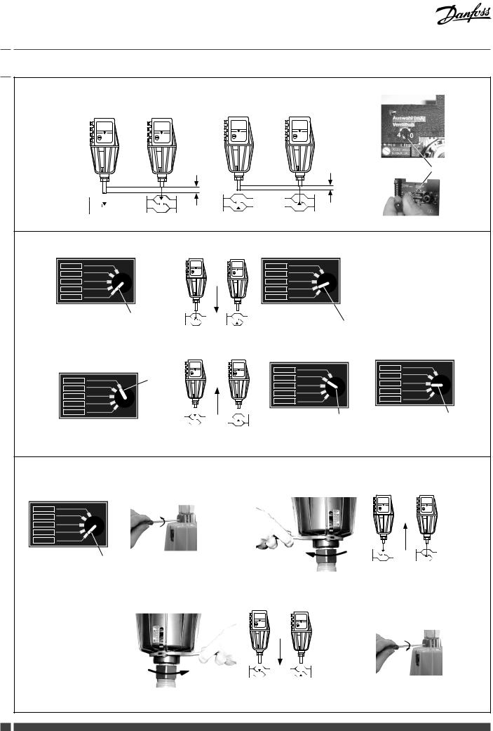
Setting the Output Signal 0(4)-20 mA
After the adjustment, the output signal is proportional to the valve stroke “h” .
The range of the output signal 0-20 mA or 4-20 mA can be set at the pot .
Adjustment is carried out by turning in the direction of the arrow up to the stop.
Operation
Rotary switch positions electrical adjustment manual
•Set rotary switch to CLOSE and the actuator runs out . After adjustment set it to “STOP”
•Set rotary switch to OPEN and the actuator runs back . After adjustment set it to “STOP”
•Set rotary switch to STOP and the actuator remains in the last positions. Set rotary switch to AUTO and the actuator is driven by the external controller
Standard settings for normal operation always have to be set.
Mechanical Manual Adjustments
(only for the actuators AMV 610, AMV-H 613)
In case of a power supply failure or a operating fault, the valve may be opened or closed.
Procedure:
1.Turn rotary switch to position “CLOSE” .
2.Loosen security screw .
3.With hook wrench (accessory) retract actuator stem .
VFG .., AFQ |
opens |
VFU 2 |
closes |
4.With hook wrench (accessory) extend actuator stem .
VFG .., AFQ |
closes |
VFU 2 |
opens |
Prior to switching to automatic operation (AUTO), it is absolutely necessary to completely turn the adjustment nut to its stop.
Tighten security screw .
If this is not observed, the valve cannot be closed. (VFU ... not be opened).
Danfoss Heating
|
|
|
|
|
|
Installation Guide |
AMV (-H) 610, 613, 633 |
|
|
|
|
|
|
|
|
|
|
Translation:
Valve stroke (Ventilhub)
External control (Externe Regelung) Limit contacts for position «OPEN» (Kontakte für Stellung “OPEN“ beschränen)
Limit contacts for position «CLOSE»
(Kontakte für Stellung “CLOSE“ beschränen)
Safety pressure limiter
(Sicherheitsdruckbegrenzer)
Safety temperature limiter
(Sicherheitstemperaturbegrenzer) Power supply (Spannungsversorgung)
Manual switch (Handschalter)
Open (Öffnen)
Close (Schließen)
Auto (Auto)
Danfoss Heating |
VI.AA.T2.3K |
DH-SMT/SI |
9 |
 Loading...