


Controller for temperature control
- EKC 202D
Manual
Introduction
Application
•The controller is used for temperature control refrigeration appliances in supermarkets.
•With many predefined applications one unit will offer you several options. Flexibility has been planned both for new installations and for service in the refrigeration trade.
Principle
The controller contains a temperature control where the signal can be received from one or two temperature sensors.
The thermostat sensors are either placed in the cold air flow after the evaporator, in the warm air flow just before the evaporator, or both. A setting will determine how great an influence the two signals are to have on the control.
A measurement of the defrost temperature can be obtained directly through the use of an S5 sensor or indirectly through the use of the S4 measurement. Four relays will cut the required functions in and out – the application determines which.
The options are the following:
•Refrigeration (compressor or relay)
•Fan
•Defrost
•Rail heat
•Alarm
•Light
The different applications are described on page 6.
Advantages
•Several applications in the same unit
•The controller has integrated refrigeration-technical functions, so that it can replace a whole collection of thermostats and timers
•Buttons and seal imbedded in the front
•Easy to remount data communication
•Two temperature references
•Digital inputs for various functions
•Clock function with super cap backup
Contents |
|
Introduction........................................................................................................ |
2 |
Operation............................................................................................................. |
3 |
Applications........................................................................................................ |
6 |
Survey of functions.......................................................................................... |
7 |
Operation........................................................................................................... |
16 |
Menu survey..................................................................................................... |
17 |
Override.............................................................................................................. |
19 |
Ordering............................................................................................................. |
19 |
Connections...................................................................................................... |
20 |
Data...................................................................................................................... |
21 |
2 |
Manual RS8EE202 © Danfoss 08-2010 |
EKC 202D |
Operation
Sensors
Up to two thermostat sensors can be connected to the controller. The relevant application determines how.
A sensor in the air before the evaporator:
This connection is primarily used when control is based on area.
A sensor in the air after the evaporator:
This connection is primarily used when refrigeration is controlled and there is a risk of a too low temperature near the products.
A sensor before and after the evaporator:
This connection offers you the possibility of adapting the thermostat, the alarm thermostat and the display to the relevant application.The signal to the thermostat, the alarm thermostat and the display is set as a weighted value between the two temperatures, and 50% will for example give the same value from both sensors.
The signal to the thermostat, the alarm thermostat and the display can be set independently of one another.
Defrost sensor
The best signal concerning the evaporator’s temperature is obtained from a defrost sensor mounted directly on the
evaporator. Here the signal may be used by the defrost function, so that the shortest and most energy-saving defrost can take place.
If a defrost sensor is not required, defrost can be stopped based on time, or S4 can be selected.
Change of temperature reference
In an impulse appliance, for example, used for various product groups. Here the temperature reference is changed easily with a contact signal on a digital input.The signal raises the normal thermostat value by a predefined amount. At the same time the alarm limits with the same value are displaced accordingly.
EKC 202D |
Manual RS8EE202 © Danfoss 08-2010 |
3 |
Digital inputs
There are two digital inputs both of which can be used for one of the following functions:
-Case cleaning
-Door contact function with alarm
-Starting a defrost
-Coordinated defrost
-Change-over between two temperature references
-Retransmission of a contact’s position via data communication
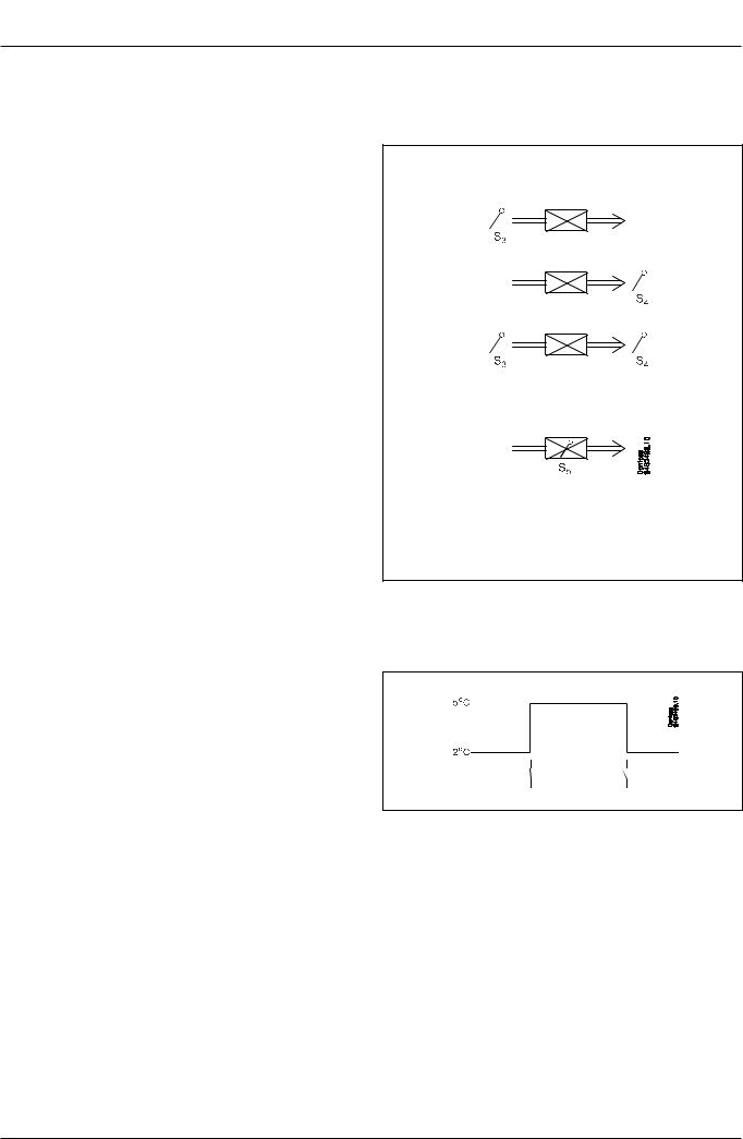
Case cleaning function
This function makes it easy to steer the refrigeration appliance through a cleaning phase.Via three pushes on a switch you change from one phase to the next phase.
The first push stops the refrigeration – the fans keep working ”Later”:The next push stops the fans
”Still later”:The final push restarts refrigeration
The different situations can be monitored on the display.
On the network a cleaning alarm is transmitted to the system unit. This alarm can be ”logged”so that proof of the sequence of events is provided.
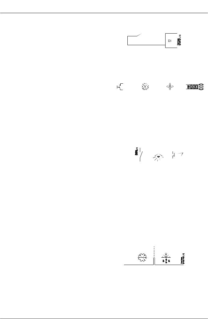
Door contact function
In cold rooms and frost rooms the door switch can turn the light on and off, start and stop the refrigeration and give alarm if the door has remained open for too long.
Defrost
Depending on the application you may choose between the following defrost methods:
Natural: |
Here the fans are kept operating during the defrost |
Electric: |
The heating element is activated |
Brine: |
The valve is kept open so that the brine can flow |
|
through the evaporator |
Start of defrost
A defrost can be started in different ways;
Interval: |
Defrost is started at fixed time intervals, e.g., every |
|
eight hour |
Refrigeration time: |
|
|
Defrost is started at fixed refrigeration time inter- |
|
vals, in other words, a low need for |
|
refrigeration will ”postpone”the coming defrost |
Schedule: |
Here defrost can be started at fixed times during |
|
the day and night. However, max. 6 times |
Contact: |
Defrost is started with a contact signal on a digital |
|
input |
Network: |
The signal for defrost is received from a system unit |
|
via the data communication |
S5 temp |
In 1:1 systems the efficiency of the evaporator can |
|
be monitored. Icing-up will start a defrost. |
Manual: |
An extra defrost can be activated from the control- |
|
ler’s lower-most button |
All the mentioned methods can be used at random – if just one of them is activated a defrost will be started.
|
|
|
|
|
|
|
|
|
|
|
|
|
|
|
|
|
|
|
|
|
|
|
|
|
|
|
|
|
|
|
|
|
|
|
|
|
|
|
|
|
|
|
|
|
|
|
|
|
|
|
|
|
|
|
|
|
|
|
|
|
|
|
|
|
|
|
|
|
|
|
|
|
|
|
|
|
|
|
|
|
|
|
|
|
|
|
|
|
|
|
|
|
|
|
|
|
|
|
|
|
|
|
|
|
|
|
|
|
|
|
|
|
|
|
|
|
|
|
|
|
|
|
|
|
|
|
|
|
|
|
|
|
|
|
|
- |
|
|
+ |
|
|
|
+ |
|
|
|
°C |
|||||
|
|
|
|
|
|
|
|
|
|
|
|
|
|
|
|
|
1 |
|
|
÷ |
|
|
|
+ |
|
|
|
Fan |
|||||
|
|
|
|
|
|
|
|
|
|
|
|
|
|
|
|
|
2 |
|
|
÷ |
|
|
|
÷ |
|
|
|
Off |
|||||
|
|
|
|
|
|
|
|
|
|
|
|
|
|
|
|
|
3 |
|
|
+ |
|
|
|
+ |
|
|
|
°C |
|||||
|
|
|
|
|
|
|
|
|
|
|
|
|
|
|
|
|
|
|
|
|
|
|
|
|
|
|
|
|
|
|
|
|
|
|
|
|
|
|
|
|
|
|
|
|
|
|
|
|
|
|
|
|
|
|
|
|
|
|
|
|
|
|
|
|
|
|
|
|
|
|
|
|
|
|
|
|
|
|
|
|
|
|
|
|
|
|
|
|
|
|
|
|
|
|
|
|
|
|
|
|
|
|
|
|
|
|
|
|
|
|
|
|
|
|
|
|
|
|
|
|
|
|
|
|
|
|
|
|
|
|
|
|
|
|
|
4 |
Manual RS8EE202 © Danfoss 08-2010 |
EKC 202D |
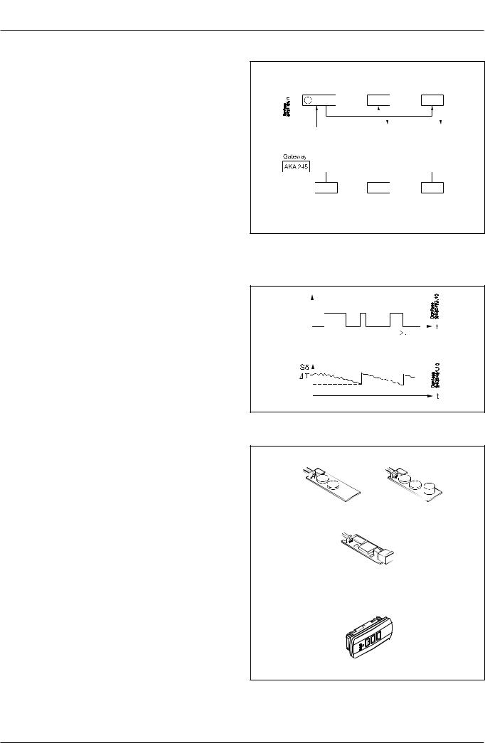
Coordinated defrost
There are two ways in which coordinated defrost can be arranged. Either with wire connections between the controllers or via data communication.
Wire connections
One of the controllers is defined to be the controlling unit and a battery module may be fitted in it so that the clock is ensured backup.When a defrost is started all the other controllers will follow suit and likewise start a defrost. After the defrost the individual controllers will move into waiting position.When all are in waiting position there will be a change-over to refrigeration.
(If just one in the group demands defrost, the others will follow suit).
Defrost via data communication
All controllers are fitted with a data communication module, and via the override function from a gateway the defrost can be coordinated.
Defrost on demand
1 Based on refrigeration time
When the aggregate refrigeration time has passed a fixed time, a defrost will be started.
2 Based on temperature
The controller will constantly follow the temperature at S5. Between two defrosts the S5 temperature will become lower the more the evaporator ices up (the compressor operates for a longer time and pulls the S5 temperature further down). When the temperature passes a set allowed variation the defrost will be started.
This function can only work in 1:1 systems
Extra module
•The controller can afterwards be fitted with an insertion module if the application requires it.
The controller has been prepared with a plug, so the module simply has to be pushed in
-Battery module
The module guarantees voltage to the controller if the supply voltage should drop out for more than four hours.The clock function can thus be protected during a power failure.
-Battery and buzzer module As above + sound buzzer
-Data communication
If you require operation from a PC, a data communication module has to be placed in the controller.
•External display
If it is necessary to indicate the temperature on the front of refrigeration appliance, a display can be mounted.The extra display will show the same information as the controller's display, but does not incorporate buttons for operation.
EKC 202D |
Manual RS8EE202 © Danfoss 08-2010 |
5 |

Applications
Here is a survey of the controller’s field of application.
A setting will define the relay outputs so that the controller’s interface will be targeted the chosen application.
On page 17 you can see the relevant settings for the respective wiring diagrams.
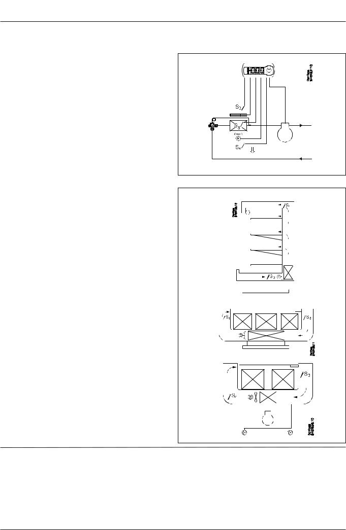
Refrigeration control with one compressor
The functions are adapted to small refrigeration systems which may be either refrigeration appliances or coldrooms.
The three relays can control the refrigeration, the defrost and the fans, and the fourth relay can be used for either alarm function, light control or rail heat control.
•The alarm function can be linked up with a contact function from a door switch. If the door remains open longer than allowed an alarm is triggered.
•The light control can also be linked up with a contact function from a door switch. An open door will switch on the light and it will remain lit for two minutes after the door has been closed again.
•The rail heat function can be used in refrigeration or freezing appliances or on the door’s heating element for frostrooms.
The fans can be stopped during defrost and they may also follow a door switch’s open/close situation.
There are several other functions for the alarm function as well as the light control, rail heat control and fans. Please refer to the respective settings.
S3 and S4 are temperature sensors.The application will determine whether either one or the other or both sensors are to be used. S3 is placed in the air flow before the evaporator. S4 after the evaporator.
A percentage setting will determine according to what the control is to be based. S5 is a defrost sensor and is placed on the evaporator.
DI1 and DI2 are contact functions that can be used for one of the following functions: door function, alarm function, defrost start, external main switch, night operation, change of thermostat reference, appliance cleaning, forced refrigeration or coordinated defrost. See the functions in settings o02 and o37.
1
Danfoss 84B2428.12
2
Danfoss 84B2429.13
3
Danfoss 84B2430.13
6 |
Manual RS8EE202 © Danfoss 08-2010 |
EKC 202D |

Survey of functions
Function |
|
|
|
|
Para- |
Parameter by operation via data |
||||
|
|
|
|
|
|
|
|
|
meter |
communication |
Normal display |
|
|
|
|
|
|
||||
|
|
|
|
|
|
|
|
|
|
|
Normally the temperature value from one of the two thermostat sensors S3 or S4 or a |
|
Display air (u56) |
||||||||
mixture of the two measurements is displayed. |
|
|
|
|
|
|
||||
In o17 the ratio is determined. |
|
|
|
|
|
|
||||
Thermostat |
|
|
|
|
|
Thermostat control |
||||
Set point |
|
|
|
|
|
Cutout °C |
||||
Regulation is based on the set value plus a displacement, if applicable.The value is set |
|
|
||||||||
via a push on the centre button. |
|
|
|
|
|
|
||||
The set value can be locked or limited to a range with the settings in r02 and r 03. |
|
|
||||||||
The reference at any time can be seen in ”u28Temp. ref” |
|
|
||||||||
Differential |
|
|
|
|
r01 |
Differential |
||||
When the temperaure is higher than the reference + the set differential, the compres- |
|
|
||||||||
sor relay will be cut in. It will cut out again when the temperature comes down to the |
|
|
||||||||
set reference. |
|
|
|
|
|
|
|
|
||
|
|
|
|
|
|
|
|
|||
|
|
|
|
|
|
|
|
|
|
|
|
|
|
|
|
|
|
|
|
|
|
|
|
Ref. |
Dif. |
|
|
|||||
|
|
|
|
|
|
|
|
|
|
|
Setpoint limitation |
|
|
|
|
|
|
||||
The controller’s setting range for the setpoint may be narrowed down, so that much |
|
|
||||||||
too high or much too low values are not set accidentally - with resulting damages. |
|
|
||||||||
|
|
|
|
|
|
|
|
|
|
|
To avoid a too high setting of the setpoint, the max. allowable reference value must |
r02 |
Max cutout °C |
||||||||
be lowered. |
|
|
|
|
|
|
||||
To avoid a too low setting of the setpoint, the min. allowable reference value must be |
r03 |
Min cutout °C |
||||||||
increased. |
|
|
|
|
|
|
||||
Correction of the display’s temperature showing |
|
|
|
|
r04 |
Disp. Adj. K |
||||
If the temperature at the products and the temperature received by the controller are |
|
|
||||||||
not identical, an offset adjustment of the shown display temperature can be carried |
|
|
||||||||
out. |
|
|
|
|
|
|
||||
Temperature unit |
|
|
|
|
r05 |
Temp. unit |
||||
Set here if the controller is to show temperature values in °C or in °F. |
|
°C=0. / °F=1 |
||||||||
|
|
|
|
|
|
|
|
|
|
(Only °C on AKM, whatever the set- |
|
|
|
|
|
|
|
|
|
|
ting) |
|
|
|
|
|
|
|
|
|
|
|
Correction of signal from S4 |
|
|
|
|
r09 |
Adjust S4 |
||||
Compensation possibility through long sensor cable |
|
|
|
|
|
|
||||
|
|
|
|
|
|
|
|
|
|
|
Correction of signal from S3 |
|
|
|
|
r10 |
Adjust S3 |
||||
Compensation possibility through long sensor cable |
|
|
|
|
|
|
||||
|
|
|
|
|
|
|
|
|
|
|
Start / stop of refrigeration |
|
|
|
|
r12 |
Main Switch |
||||
With this setting refrigeration can be started, stopped or a manual override of the |
|
|
||||||||
outputs can be allowed. |
|
|
|
|
|
1: Start |
||||
Start / stop of refrigeration can also be accomplished with the external switch func- |
|
0: Stop |
||||||||
tion connected to a DI input. |
|
|
|
|
|
-1: Manual control of outputs allowed |
||||
Stopped refrigeration will give a ”Standby alarm”. |
|
|
|
|
|
|
||||
Night setback value |
|
|
|
|
r13 |
Night offset |
||||
The thermostat’s reference will be the setpoint plus this value when the controller |
|
|
||||||||
changes over to night operation. (Select a negative value if there is to be cold ac- |
|
|
||||||||
cumulation.) |
|
|
|
|
|
|
||||
Selection of thermostat sensor |
|
|
|
|
r15 |
Ther. S4 % |
||||
Here you define the sensor the thermostat is to use for its control function. S3, S4, or a |
|
|
||||||||
combination of them.With the setting 0%, only S3 is used (Sin).With 100%, only S4. |
|
|
||||||||
|
|
|
|
|
|
|
|
|
|
|
Activation of reference displacement |
|
|
|
|
r39 |
Th. offset |
||||
When the function is changed to ON the thermostat differential will be increased by |
|
|
||||||||
the value in r40. Activation can also take place via input DI1 or DI2 (defined in o02 or |
|
|
||||||||
o37). |
|
|
|
|
|
|
||||
|
|
|
|
|
|
|
|
|
|
|
|
|
|
|
|
|
|
|
|
|
|
|
|
|
|
|
|
|
|
|
|
|
|
|
|
|
|
|
|
|
|
|
|
|
|
|
|
|
|
|
|
|
|
|
|
|
|
|
|
|
|
|
|
|
|
EKC 202D |
Manual RS8EE202 © Danfoss 08-2010 |
7 |

Value of reference displacement |
r40 |
Th. offset K |
The thermostat reference and the alarm values are shifted the following number of |
|
|
degrees when the displacement is activated. Activation can take place via r39 or input |
|
|
DI |
|
|
|
|
Night setbck |
|
|
(start of night signal) |
|
|
Forced cool. |
|
|
(start of forced cooling) |
Alarm |
|
Alarm settings |
|
|
|
The controller can give alarm in different situations.When there is an alarm all the |
|
With data communication the impor- |
light-emitting diodes (LED) will flash on the controller front panel, and the alarm relay |
|
tance of the individual alarms can be |
will cut in. |
|
defined. Setting is carried out in the |
|
|
“Alarm destinations”menu. |
Alarm delay (short alarm delay) |
A03 |
Alarm delay |
If one of the two limit values is exceeded, a timer function will commence.The alarm |
|
|
will not become active until the set time delay has been passed.The time delay is set |
|
|
in minutes. |
|
|
|
|
|
Time delay for door alarm |
A04 |
DoorOpen del |
The time delay is set in minutes. |
|
|
The function is defined in o02 or in o37. |
|
|
Time delay for cooling (long alarm delay) |
A12 |
Pulldown del |
This time delay is used during start-up, during defrost, immediately after a defrost. |
|
|
There will be change-over to the normal time delay (A03) when the temperature has |
|
|
dropped below the set upper alarm limit. |
|
|
The time delay is set in minutes. |
|
|
Upper alarm limit |
A13 |
HighLim Air |
Here you set when the alarm for high temperature is to start.The limit value is set in |
|
|
°C (absolute value).The limit value will be raised during night operation.The value is |
|
|
the same as the one set for night setback, but will only be raised if the value is posi- |
|
|
tive. |
|
|
The limit value will also be raised in connection with reference displacement r39. |
|
|
Lower alarm limit |
A14 |
LowLim Air |
Here you set when the alarm for low temperature is to start.The limit value is set in °C |
|
|
(absolute value). |
|
|
The limit value will also be raised in connection with reference displacement r39. |
|
|
Delay of a DI1 alarm |
A27 |
AI.Delay DI1 |
A cut-out/cut-in input will result in alarm when the time delay has been passed.The |
|
|
function is defined in o02. |
|
|
Delay of a DI2 alarm |
A28 |
AI.Delay DI2 |
A cut-out/cut-in input will result in alarm when the time delay has been passed.The |
|
|
function is defined in o37 |
|
|
Signal to the alarm thermostat |
A36 |
Alarm S4% |
Here you have to define the ratio between the sensors which the alarm thermostat |
|
|
has to use. S3, S4 or a combination of the two. |
|
|
With setting 0% only S3 is used.With 100% only S4 is used |
|
|
|
|
Reset alarm |
|
|
EKC error |
|
|
|
Compressor |
|
Compressor control |
|
|
|
The compressor relay works in conjunction with the thermostat.When the thermo- |
|
|
stat calls for refrigeration will the compressor relay be operated. |
|
|
|
|
|
Running times |
|
|
To prevent irregular operation, values can be set for the time the compressor is to run |
|
|
once it has been started. And for how long it at least has to be stopped. |
|
|
The running times are not observed when defrosts start. |
|
|
|
|
|
Min. ON-time (in minutes) |
c01 |
Min. On time |
Min. OFF-time (in minutes) |
c02 |
Min. Off time |
Reversed relay function for D01 |
c30 |
Cmp relay NC |
0: Normal function where the relay cuts in when refrigeration is demanded |
|
|
1: Reversed function where the relay cuts out when refrigeration is demanded (this |
|
|
wiring produces the result that there will be refrigeration if the supply voltage to the |
|
|
controller fails). |
|
|
The LED on the controller’s front will show whether refrigeration is in progress. |
|
Comp Relay |
|
|
Here you can read the status of the |
|
|
compressor relay, or you can force- |
|
|
control the relay in the ”Manual |
|
|
control”mode |
8 |
Manual RS8EE202 © Danfoss 08-2010 |
EKC 202D |
 Loading...