


Montageund Betriebsanleitung / Mounting and Installation Guide
Edelstahl Verteilersysteme
(für VX-F) / Stainless Steel
Distribution Systems (for VX-F)
Danfoss vorgefertigte Edelstahl Verteilersysteme für Fussbodenheizung / Danfoss prefabricated solutions for floor heating
Plug&Play Verteilersysteme/ Plug&Play distributionsystems
für VX-F
Montageanleitung / Installation Guide |
Edelstahl Verteilersystem für VX-F/ Stainless steel distribution system for VX-F |
|
|
Verteilersystem für VX-F Station |
|
|
Distribution unit for VX-F units |
1. INHALT / CONTENT |
|
|
1.0 |
Inhalt / Content......................................................................................................................................................................................................................... |
2 |
2.0 |
Anschluss, Sicherheit, Handhabung / Connection, Safety, Handling.................................................................................................................... |
3 |
3.0 |
Installationsanleitung generell / Installation instructions, general....................................................................................................................... |
5 |
4.0 |
Produkt Introduktion / Product introduction................................................................................................................................................................ |
6 |
5.0 |
Hauptkomponente & Anschluss / Main components & Connection.................................................................................................................... |
8 |
6.0 |
Montage / Mounting........................................................................................................................................................................................................... |
10 |
7.0 |
Montage in Einbauschrank / Mounting in recess box............................................................................................................................................. |
11 |
8.0 |
Einstellung und Inbetriebnahme / Adjustment and commissioning................................................................................................................ |
14 |
9.0 |
Regeltechnik - Fussbodenheizung / Control - Floor heating................................................................................................................................ |
16 |
10.0 |
Wartung / Maintenance...................................................................................................................................................................................................... |
18 |
11.0 |
EU Gutachten / EU Declaration of Conformity........................................................................................................................................................... |
19 |
12.0 |
Inbetriebnahmezertifikat / Commissioning Certificate.......................................................................................................................................... |
20 |
2 | © Danfoss | Produced by Danfoss Redan A/S | 2016.12 |
VI.LZ.O1.5B |
Montageanleitung / Installation Guide |
Edelstahl Verteilersystem für VX-F/ Stainless steel distribution system for VX-F |
2. ANSCHLUSS, SICHERHEIT, HANDHABUNG / CONNECTION, SAFETY, HANDLING
GERMAN - DE
Anleitung
Bitte lesen Sie diese Anleitung vor der Installation und Inbetriebnahme des Verteilersystems sorgfältig durch. Der Hersteller übernimmt keine Haftung für Ausfälle oder Schäden, die durch das Nichtbeachten der Hinweise in dieser Betriebsanleitung entstehen. Lesen und befolgen Sie sämtliche Anweisungen, um Verletzungen und/oder Sachschäden zu vermeiden. Das Überschreiten der empfohlenen Betriebsparameter erhöht beträchtlich das Risiko für Verletzungen und/oder Sachschäden.
Die Einbau-, Inbetriebnahmeund Wartungsarbeiten müssen von (für Heizungsund Anschlussarbeiten) qualifiziertem und autorisiertem Personal durchgeführt werden.
Sobald die Station eingebaut ist und sich in Betrieb befindet, besteht in der Regel keine Notwendigkeit, die Einstellungen oder andere Funktionen zu verändern. Das Verteilersystem ist sehr betriebssicher und einfach zu bedienen.
Energiequelle
Das Verteilersystem ist in erster Linie für den Anschluss an eine Fernwärmequelle ausgelegt. Alternative Energiequellen können verwendet werden, wenn die Betriebsbedingungen zu jeder Zeit derjenigen der Fernwärme entsprechen.
Anwendung
Die Danfoss Edelstahl Verteilersysteme sind vorgefertigte Heizkreisverteiler für Fußbodenheizung, die für den separaten Einbau oder für die Montage zusammen mit den bekannten Danfoss Wohnungsstationen vorbereitet sind.
Werkstoffauswahl
Verwenden Sie nur Werkstoffe, die den lokalen Vorschriften entsprechen.
Korrosion
Der maximale Chlorgehalt des Mediums darf nicht mehr als 300 mg/l betragen. Wenn der empfohlene Chlorgehalt überschritten wird, steigt das Korrosionsrisiko beträchtlich.
Lagerung und Handhabung
Vor dem Einbau muss/müssen dieVerteilersystem(e) in einem trockenen und beheizten (d. h. frostfreien) Raum gelagert werden. (Relative Luftfeuchtigkeit max. 80 % und Lagertemperatur 5–70 °C). Die Verteilersysteme dürfen nicht höher als im Werk gestapelt werden. Verteilersysteme, die in Kartons geliefert werden, müssen an den Handgriffen derVerpackung angehoben werden. ZumTransportieren/Befördern über große Entfernungen müssen die Verteilersysteme auf Paletten platziert werden.
Heben Sie dieVerteilersysteme nach Möglichkeit nicht an den Rohren an, da dadurch Leckagen entstehen können.
ZIEHEN Sie die Anschlüsse nach dem Transport erneut FEST.
Entsorgung
DieVerteilersysteme bestehen aus Materialien, die nicht zusammen mit dem Hausmüll entsorgt werden dürfen. Die gesammte Energieversorgung unterbrechen und bitte zerlegen Sie das Produkt zur entsorgung in Einzelteile und führen Sie sie gemäß den geltenden örtlichen Vorschriften sortenrein der Entsorgung zu.
Anschluss
Eine Unterbrechung der gesamten Energieversorung zu der Station muss jederzeit möglich sein, (hierunter auch Stromzufuhr).
Potentialausgleich / Erdung
Unter Potentialausgleich versteht man alle Maßnahmen zum Beseitigen elektrischer Potentialunterschiede (Kontaktspannungen), die zwischen z.B zwei Rohrleitungen auftreten können. Der Potentialausgleich ist eine wichtige Maßnahme zum Schutz gegen elektrischen Schlag. Potentialausgleich reduziert Korrosion im Wärmetauscher, Durchlauferhitzer, Fernwärmestationen und Sanitärinstallationen.
Potentialausgleich sollte nach den Bestimmungen 60364-4-41: 2007 und IEC 60364-5-54: 2011 erfolgen.
Bindungsstelle ist mit einem Erdungssymbol auf der rechten unteren Ecke der Montageplatte markiert und es gibt ein Loch in der Montageplatte und ein Etikett mit Erdungssymbol.
Warnung! Heiße Oberflächen
Einige Teile des Verteilersystems können sehr heiß werden und Verbrennungen verursachen. Seien Sie sehr vorsichtig, wenn Sie sich in der direkten Umgebung der Station befinden.
Notfälle
Im Falle von Feuer, Leckagen oder sonstigen Gefahren, sind, wenn möglich, alle Energieversorgungsanschlüsse des Verteilersystems zu schließen. Zudem ist Abhilfe durch professionelle Fachkräfte zu schaffen.
Warnung vor Transportschäden
Beim Erhalt und vor dem Einbau ist dasVerteilersystem auf eventuelle Transportschäden zu prüfen. Das Verteilersystem ist mit größter Vorsicht und Sorgfalt zu bewegen und zu bedienen.
Hinweis – Festziehen der Anschlüsse
Vor dem Befüllen der Fernwärmestation mit Wasser sind ALLE Rohrleitungsanschlüsse festzuziehen, da sie von Vibrationen während desTransports möglicherweise gelockert wurden und Leckagen entstanden sind. Sobald die Fernwärmestation befüllt wurde und warm ist, sind ALLE Rohrleitungsanschlüsse erneut festzuziehen.
ZIEHEN SIE DIE ROHRLEITUNGSANSCHLÜSSE NICHT ZU FEST AN .
Handhabung
Wir empfehlen, beim Handhaben und Einbauen der Fernwärmestation geeignetes und sicheres Schuhwerk zu tragen.
Bitte bemerken: Eingriffe und Nacharbeiten an unseren Komponenten führen zum Verlust der Gewährleistung.
VI.LZ.O1.5B |
© Danfoss | Produced by Danfoss Redan A/S | 2016.12 | 3 |
Montageanleitung / Installation Guide |
Edelstahl Verteilersystem für VX-F/ Stainless steel distribution system for VX-F |
2. ANSCHLUSS, SICHERHEIT, HANDHABUNG / CONNECTION, SAFETY, HANDLING
ENGLISH - GB
Instructions
Please read these instructions carefully before installing and commissioning this unit. The manufacturer accepts no liability for loss or damage resulting from failure to comply with these instructions for use. Read and follow these instructions carefully to prevent the risk of physical injury and/or damage to property. Exceeding the recommended operating parameters appreciably increases the risk of personal injury and/or damage to property.
Installation, commissioning and maintenance must be carried out by qualified and authorised personnel (both plumbing and electrical work).
Once the system has been installed and is operating, there is normally no need to alter the settings or other functions. The distribution system unit is very reliable and easy to operate.
Heat source
The distribution system is primarily designed for connection to district heating. Alternative energy sources can be used if the operating conditions are equivalent to district heating at all times.
Application
The Danfoss stainless steel distribution systems are prefabricated solutions for floor heating, which can be installed separately or be implemented with the Danfoss flat station range, in connection with a boiler or as an extension of an existing heating system.
Choise of materials
Only use materials that comply with local regulations.
Corrosion
The maximum chlorine content of the medium must not be higher than 300 mg/l. The risk of corrosion increases considerably if the recommended chlorine content is exceeded.
Storage
Before installation, the unit(s) must be stored in a dry, heated (i.e. frostfree) room.
(Relative humidity max. 80% and storage temp. 5–70°C).
The units must not be stacked higher than the limit at the factory. Units supplied in cardboard packaging must be lifted using the handles incorporated in the packaging. Units must be placed on pallets for transport/moving across large distances.
As far as possible, do not lift the unit by the pipes. Retighten ALL pipe connections after transport/moving.
Disposal
Dispose of the packaging in accordance with the local regulations for disposal of used packaging materials. The unit is made of materials that cannot be disposed of together with household waste.
Close all energy sources and disconnect all connection pipes. Disconnect and dismantle the product for disposal in accordance with the applicable local regulations for the disposal of the individual components.
Connection
It must be possible to cut off all energy sources to the system – including electrical connections – at all times.
Potential equalization/grounding
Potential equalization is an electrical equalizer connection to secure against user contact with dangerous voltage, which may occur for example between two piping systems. Potential equalization reduces corrosion in heat exchangers, water heaters, district heating
units and plumbing installations.
Potential bonding should be carried out according to 60364-4-41: 2007 and IEC 60364-5-54: 2011.
Bonding poing is marked on the mounting plate below right corner with an earthing symbol and there will be a hole in the station mounting plate and a label with earth symbol.
Warning! Hot surfaces
Parts of the unit may be very hot and can cause burn injuries.
Be very careful when you are in the immediate vicinity of the unit
Emergencies
In the event of fire, leaks or other hazards, immediately shut off all sources of energy to the unit, if possible, and call for appropriate assistance.
If the domestic hot water is discoloured or malodorous, shut off all ball valves on the unit notify all users and call for professional assistance without delay.
Warning about damage during transport
On reception of the unit, and before installing it, check for any evidence of damage during transport.
The unit must be handled and moved with the greatest care and attention.
NB! - Tightening of connections
Before filling the unit with water, ALL pipe connections MUST be retightened, as vibrations during transport may have caused leaks. Once the unit has been filled and the system is hot, ALL pipe connections MUST be retightened once more. DO NOT OVERTIGHTEN THE PIPE CONNECTIONS.
Handling
We recommend that you wear suitable safety footwear while handling and installing the unit.
Please note: Eingriffe und Nacharbeiten an unseren Komponenten führen zum Verlust der Gewährleistung.
4 | © Danfoss | Produced by Danfoss Redan A/S | 2016.12 |
VI.LZ.O1.5B |
Montageanleitung / Installation Guide |
Edelstahl Verteilersystem für VX-F/ Stainless steel distribution system for VX-F |
3. INSTALLATIONSANLEITUNG GENERELL / INSTALLATION INSTRUCTIONS, GENERAL
GERMAN - DE
Generell
Die Einbau-, Anschlussund Wartungsarbeiten bei dem System dürfen nur von qualifiziertem und autorisiertem Personal durchgeführt werden. Der Einbau muss immer gemäß den geltenden Vorschriften und in Übereinstimmung mit dieser Anleitung erfolgen.
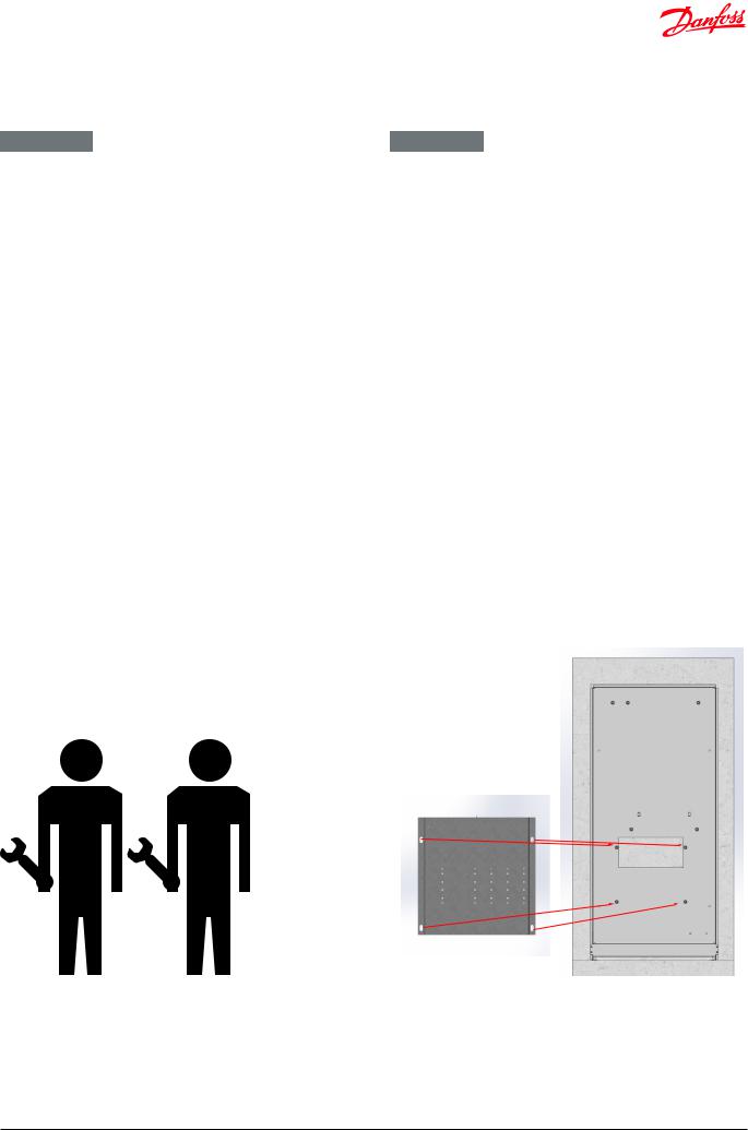
Das System muss so eingebaut werden, dass sie frei zugänglich ist und ohne unnötige Unterbrechungen gewartet werden kann. Heben Sie das Verteilersystem an der Montage-/Rückplatte an. Befestigen Sie ihn dann an einer stabilenWand oder in den Einbauschrank, indem Sie vier robuste Bolzen, Schrauben oder Spannbolzen in die vier Bohrlöchern in der Montage-/Rückplatte einsetzen und diese festziehen.
Spülen Sie vor der Inbetriebnahme die Hausverrohrung gründlich durch, um Verunreinigungen zu entfernen. Prüfen und Reinigen Sie auch die Schmutzfänger in der Fernwärmestation.
Prüfung und Anschlüsse
Ziehen Sie vor dem Befüllen des Systems mit Wasser erneut alle Rohrleitungsanschlüsse fest, da sie von Vibrationen und Erschütterungen während des Transports möglicherweise gelockert wurden und Leckagen entstanden sind. Ziehen Sie, sobald das System mit Wasser gefüllt wurde, die Rohrleitungsanschlüsse erneut fest, bevor Druckprüfungen zur Erkennung von Leckagen durchgeführt werden. Prüfen Sie nach der Erwärmung des Systems alle Anschlüsse und ziehen Sie sie, sofern erforderlich, erneut fest.
Bitte beachten Sie, dass die Anschlüsse EPDM-Dichtungen aufweisen können. Aus diesem Grund ist es wichtig, dass Sie die Überwurfmuttern NICHT ZU FEST ANZIEHEN. Zu fest angezogene Überwurfmuttern können zu Leckagen führen. Leckagen, die durch zu fest angezogene Überwurfmuttern oder durch dasVersäumnis, Anschlüsse erneut festzuziehen, entstanden sind, fallen nicht unter die Gewährleistung.
ENGLISH - GB
General
The installation, connection and maintenance of the system must be performed by qualified and authorised personnel. Installation must always be performed in accordance with the applicable legislation and in compliance with these instructions.
The system must be installed so that it is freely accessible and can be maintained without unnecessary disruption. Lift the unit by its mounting plate/rear section (to maximum extent do not lift the unit by the pipes) and secure it to a solid wall or in the recess box using 4 expansion bolts or the like positioned in the two bore holes in the mounting plate. It is recommended that at least two people are involved in the installation.
Before commissioning, rinse all the pipes in the household piping system thoroughly to remove any impurities, and check and clean the dirt strainers in the unit.
Test and connections
Before filling the system with water, retighten all the pipe connections because vibrations and shocks during transport and handling may have caused leaks. Once the system has been filled with water, tighten all the pipe connections once more before performing pressure test for leaks. After heating of the system, check all the connections and retighten if necessary.
Please note that the connections may feature EPDM rubber gaskets! Therefore, it is important that you DO NOT OVERTIGHTEN the union nuts. Overtightening may result in leaks.
Leaks caused by overtightening or failure to retighten connections are not covered by the warranty.
VI.LZ.O1.5B |
© Danfoss | Produced by Danfoss Redan A/S | 2016.12 | 5 |

Montageanleitung / Installation Guide Edelstahl Verteilersystem für VX-F/ Stainless steel distribution system for VX-F
4. PRODUKT INTRODUKTION / PRODUCT INTRODUKTION
GERMAN - DE ENGLISH - GB
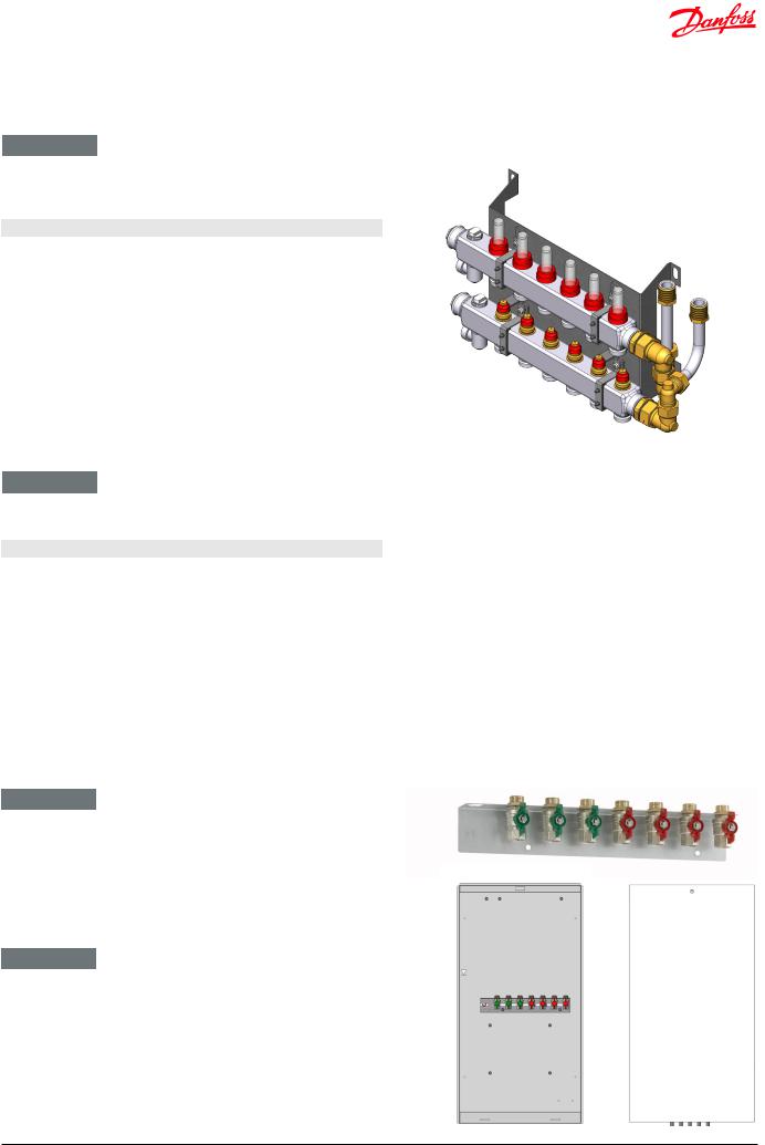
Die Danfoss Edelstahl Verteilersysteme sind vorgefertigte Heizkreisverteiler für Fußbodenheizung, die für den separaten Einbau oder für die Montage zusammen mit den bekannten Danfoss Wohnungsstationen Type VX-F vorbereitet sind.
Durch diese Plug & Play Konstruktionder Fußbodenverteiler können die Montagezeiten bei der Hausinstallation erheblich verkürzt werden.
Die Systeme sind als Standardlösungen von 3 bis 12 Heizkreise erhältlich und beinhalten alle einem Endstück mit manueller Entlüftung und Entleerung.
Zusätzlich enthalten die Lösungen einen Durchflussmesser zur Aufrechterhaltung der bestimmten Durchflussrate.
Die Verteilersysteme können mit fest verdrahtetem Heizkreisregler FH-WC 230 V und Thermo-Motoren TWA-A NC gemäß Anzahl der Heizkreise versehen verden.
Die Systeme können in Unterputzausführung mit Einbauschrank oder in Aufputzausführung montiert werden.
Einbauschränke für Unterputzmontage sind in zwei Größen erhältlich - H1350/B690/T150 mm und 1350/B850/T150 mm. Breite 690 mm passt zu Verteilersystemen mit bis zu 7 Heizkreisen und Breite 850 mm passt zu Verteilersystemen mit 7 bis 11 Heizkreisen.
Ein Kugelhahn-Set mit Montageschiene für die einfache Montage im Unterputzschrank eingebaut, und ist auch für Montage auf der Wand ist optional erhältlich.
Anpassungsfähige Lösungen
Die Danfoss Verteilersysteme sind für den Einbau zusammen mit den Danfoss Wohnungsstationen VX-F vorbereitet .
The Danfoss stainless steel distribution systems are prefabricated solutions for floor heating, which can be installed separately or be implemented with the Danfoss VX-F flat station range.
These solutions make it easier for the installer to order a ready-made plug & play construction for mounting of distribution pipes for the building section.
The systems are available as standard solutions with 3 to 12 connections and include manual air vent and drain valve.
In addition the solutions include a flow meter to maintain the designated flow rate.
The solutions can be fitted with a hard-wired master controller and thermo-actuators TWA-A NC for control of the floor heating system.
The distribution systems are used as built-in variants with a recess box, or as on the wall mounted variants.
Recess boxes for built-in variants are available in two sizes H1350/ W690/D150 mm and H1350/W850/D150 mm, - width 690 mm for distribution systems with up to 7 connections and width 850 mm for distribution systems with 7 to11 connections.
A mounting rail with 76 mm ball valves for easy mounting is mounted in the recess box or and is also available as an option for mounting on the wall.
Flexible solutions
The Danfoss distribution systems are prepared for implementation with the Danfoss flat station ranges VX-F.
6 | © Danfoss | Produced by Danfoss Redan A/S | 2016.12 |
VI.LZ.O1.5B |
Montageanleitung / Installation Guide |
Edelstahl Verteilersystem für VX-F/ Stainless steel distribution system for VX-F |
4. PRODUKT INTRODUKTION / PRODUCT INTRODUKTION
GERMAN - DE
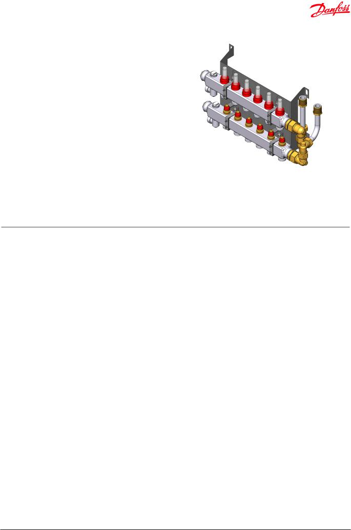
Verteilersystem für VX-F: Verteilersystem für Fussbodenheizung ohne Beimischkreis, mit Durchflussmesser. Die Variante bieten 3 bis 12 Abgänge.
Typ |
Bestell-Nr. |
Verteilerstation für VX-F, mit 3 Heizkreisen |
145H0503 |
|
|
Verteilerstation für VX-F, mit 4 Heizkreisen |
145H0504 |
|
|
Verteilerstation für VX-F, mit 5 Heizkreisen |
145H0505 |
|
|
Verteilerstation für VX-F, mit 6 Heizkreisen |
145H0506 |
Verteilerstation für VX-F, mit 7 Heizkreisen |
145H0507 |
Verteilerstation für VX-F, mit 8 Heizkreisen |
145H0508 |
|
|
Verteilerstation für VX-F, mit 9 Heizkreisen |
145H0509 |
|
|
Verteilerstation für VX-F, mit 10 Heizkreisen |
145H0510 |
|
|
Verteilerstation für VX-F, mit 11 Heizkreisen |
145H0511 |
|
|
Verteilerstation für VX-F, mit 12 Heizkreisen |
145H0512 |
|
|
ENGLISH - GB
Distribution unit for VX-F: Distribution system for floor heating without shunt, with flow meter. This variant is available with 3 to 12 connections.
Type |
Code No. |
Distribution unit for VX-F, with 3 heating circuits |
145H0503 |
|
|
Distribution unit for VX-F, with 4 heating circuits |
145H0504 |
Distribution unit for VX-F, with 5 heating circuits |
145H0505 |
|
|
Distribution unit for VX-F, with 6 heating circuits |
145H0506 |
|
|
Distribution unit for VX-F, with 7 heating circuits |
145H0507 |
|
|
Distribution unit for VX-F, with 8 heating circuits |
145H0508 |
|
|
Distribution unit for VX-F, with 9 heating circuits |
145H0509 |
|
|
Distribution unit for VX-F, with 10 heating circuits |
145H0510 |
|
|
Distribution unit for VX-F, with 11 heating circuits |
145H0511 |
|
|
Distribution unit for VX-F, with 12 heating circuits |
145H0512 |
|
|
GERMAN - DE
Montageschiene mit Kugelhähnen für einfache Montage auf der
Wand ist als Option erhältlich.
Einbauschränke einschl. Montageschiene mit Kugelhähnen für Unterputzmontage und Tür für Einbauschränke sind als Option erhältlich, sowie auch Montagefüße für Einbauschränke.
ENGLISH - GB
Mounting rail set with ball valves available as a pre-assembled accessory set for mounting on the wall.
Recess boxes incl. mounting rail set with ball valves and door for recess boxes are also available as an option, - as well as mounting feet for recess boxes.
VI.LZ.O1.5B |
© Danfoss | Produced by Danfoss Redan A/S | 2016.12 | 7 |
Montageanleitung / Installation Guide |
Edelstahl Verteilersystem für VX-F/ Stainless steel distribution system for VX-F |
5. HAUPTKOMPONENTE & ANSCHLUSS / MAIN COMPONENTS & CONNECTION
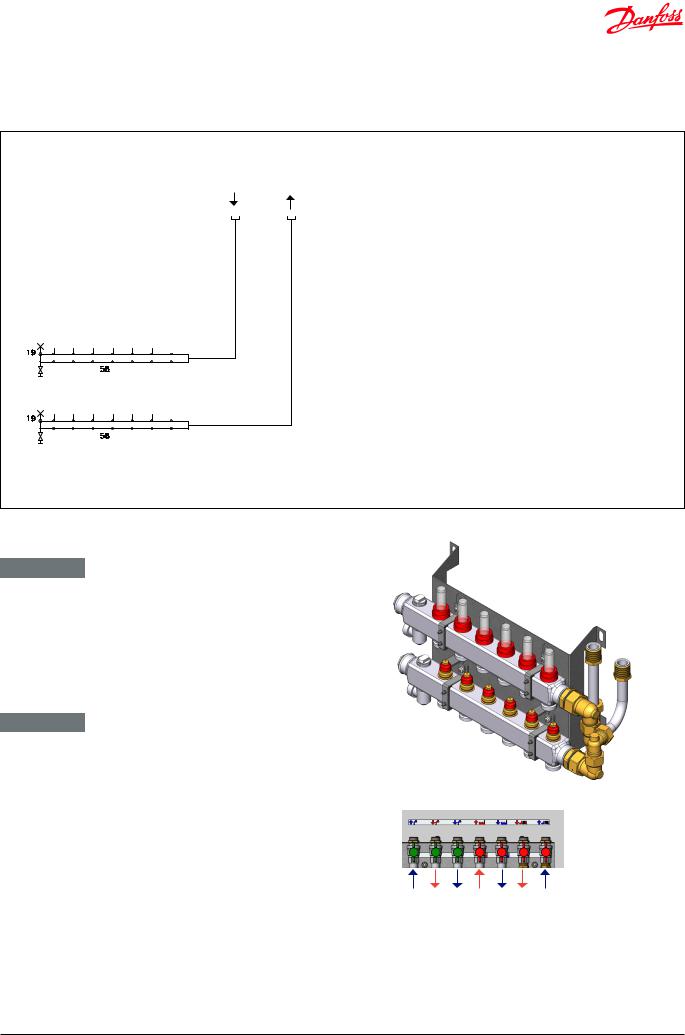
VERTEILERSYSTEM FÜR VX-F |
Fussboden |
Fussboden |
|
DISTRIBUTION SYSTEM FÜR VX-F |
Vorlauf / |
Rücklauf |
|
Floor heating |
Floor heating |
||
|
|||
|
Supply |
Return |
|
GERMAN - DE |
|
ENGLISH - GB |
|
||
19 |
Endstück mit manueller Entlüftung |
19 |
Manualairventanddrainvalve |
|||
58 |
Verteiler mit 7 Anschlüssen, mit Durchflussmesser |
58 |
Manifoldw.7connectingpieces, with flow meter |
|||
GERMAN - DE
Abmessungen:
H 227 x B 478 - 810,5 x T 153 mm
Anschlussdimensionen: G ¾” (Innengewinde)
ENGLISH - GB
Dimensions:
H 227 x W 478 - 810,5 x D 153 mm
Connection sizes: G ¾” (internal thread)
| <![if ! IE]> <![endif]>KW / DCW |
<![if ! IE]> <![endif]>TWW / DHW |
<![if ! IE]> <![endif]>KW / DCW |
<![if ! IE]> <![endif]>FW Vorlauf / DH supply |
<![if ! IE]> <![endif]>FW Rücklauf / DH return |
<![if ! IE]> <![endif]>FBH Vorlauf / DH supply |
<![if ! IE]> <![endif]>FBH Rücklauf / FH return |
8 | © Danfoss | Produced by Danfoss Redan A/S | 2016.12 |
VI.LZ.O1.5B |
 Loading...