


Data Sheet
Eco-Damper
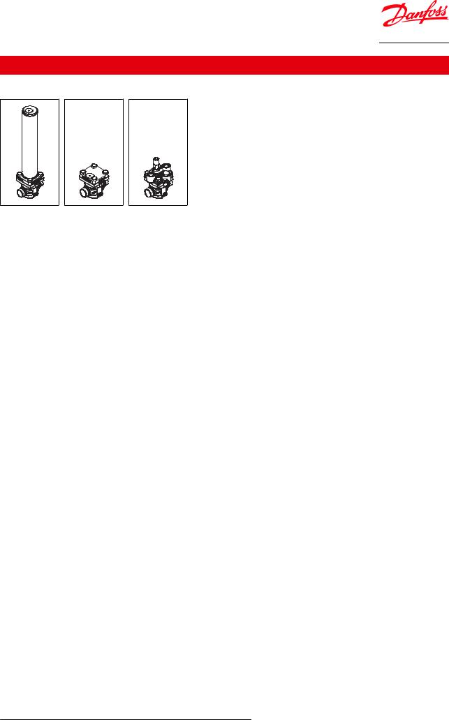
ICD damper, ICC Check valve and ICS control valve
(3 valve) system build on the ICV modular concept
The Danfoss Eco-damper solution is a 3 component (3 valve) system build on the ICV modular concept.
Each component consists of an ICV housing and 1 of 3 modules performing the functions Dampening (ICD), Non-return (ICC) and Control (ICS 1 or 3 pilots) respectively.
The Danfoss Eco-damper solution is used in the economizer line of typical screw compressors to dampen the pulsations from the compressor.
The Eco damper system is designed for high damping efficiency over a broad band of low frequencies with neglectable pressure drop.
It comes in sizes 32 and 50 and is offered from a parts program giving a wide variety of connection types and sizes.
The ICD is a unique damping system combining the Helmholz, Quarter wave and Expansion chamber principles into a broad band damper, able to reduce the Ammonia pulsations by 30% to 80% for critical frequencies in the frequency range of 100 to 500 Hz.
AI310433586905en-000201

Eco-Damper - ICD damper, ICC Check valve and ICS control valve
Features
•Designed for Industrial Refrigeration applications for a maximum working pressure of 52 bar / 754 psig.
•Applicable to R717 (Ammonia)
•Direct welded connections
•Connection types include butt weld, socket weld and solder connections
•Low temperature steel body
•Low weight and compact design
•The 3 top covers can be turned in any of 4 orientations without affecting the individual functions
•Manual opening of the solenoid valve (ie. the line) possible
•Robust PTFE seat secures long lasting solenoid valve function
•Service friendly design
© Danfoss | Climate Solutions | 2021.12 |
AI310433586905en-000201 | 2 |
Eco-Damper - ICD damper, ICC Check valve and ICS control valve
Portfolio overview
ICD, ICC, ICS 32 & 50
Table 1: Portfolio overview
Description |
ICD, ICC, ICS 32 |
ICD, ICC, ICS 50 |
|||
Valve body/connection material |
Steel |
Steel |
|||
|
|
|
EN 10220 |
EN 10220 |
|
|
|
|
ANSI (B 36.10) |
ANSI (B 36.10) |
|
Connection standard |
ANSI (B 16.11) |
ANSI (B 16.11) |
|||
|
|
|
EN 1254-1 |
EN 1254-1 |
|
|
|
|
ANSI (B 16.22) |
ANSI (B 16.22) |
|
|
|
|
Butt weld |
Butt weld |
|
Connection type |
Socket weld |
Socket weld |
|||
|
|
|
Solder connection |
Solder connection |
|
Min. opening differential pressure |
ICS = 0,07 bar (1 psi) |
ICS = 0,07 bar (1 psi) |
|||
ICC = 0,04 bar (0.6 psi) |
ICC = 0,04 bar (0.6 psi) |
||||
|
|
|
|||
Pressure differential for fully opening of the ICS |
ICS = 0,2 bar (2.9 psi) |
ICS = 0,2 bar (2.9 psi) |
|||
and ICC valves |
ICC = 0,08 bar (1.2 psi) |
ICC = 0,08 bar (1.2 psi) |
|||
K |
|
(m3/h) |
ICC = 16.6 |
ICC = 40.4 |
|
v |
ICD = 17.7 |
ICD = 39.4 |
|||
|
|
||||
Cv (USgal/min) |
ICC = 19.3 |
ICC = 47 |
|||
ICD = 20.6 |
ICD = 45.9 |
||||
|
|
|
ICD Temp. Range from -20 °C – 150 °C / - 4 °F – 302 °F |
ICD Temp. Range from -20 °C – 150 °C / - 4 °F – 302 °F |
|
Temperature range |
ICC Temp. Range from -60 °C – 120 °C / -76 °F – 248 °F |
ICC Temp. Range from -60 °C – 120 °C / -76 °F – 248 °F |
|||
|
|
|
ICS Temp. Range from -60 °C– 120 °C / -76 °F – 248 °F |
ICS Temp. Range from -60 °C – 120 °C / -76 °F – 248 °F |
|
Max. working pressure |
52 bar / 754 psig |
52 bar / 754 psig |
|||
|
|
|
|
|
|
© Danfoss | Climate Solutions | 2021.12 |
AI310433586905en-000201 | 3 |

Eco-Damper - ICD damper, ICC Check valve and ICS control valve
Functions
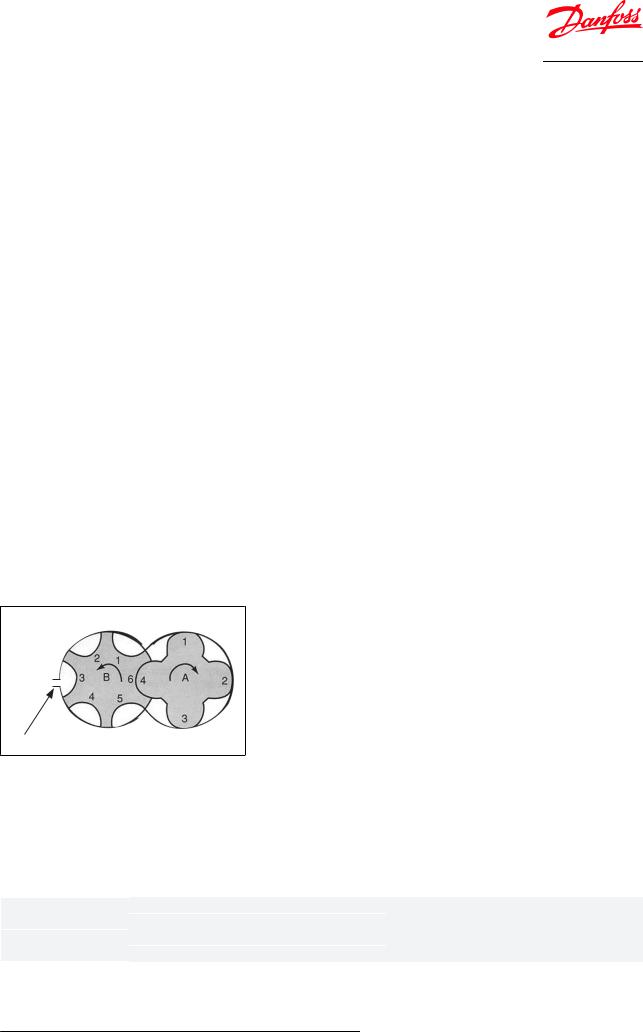
Figure 1: Functional diagram
ICD |
|
Pipe Clamp |
Fixation Rod |
A |
|
|
|
|
|
ICS |
|
Compressor |
ICC |
|
|
B |
|
B |
|
|
|
|
Y |
Mass flow direction |
Z |
|
|
|
|
|
|
Pulsation direction |
|
|
|
Though the refrigerant flow in the economizer line is towards the compressor, the pulsations moves in the opposite direction. Due to this phenomenon the sequence of the 3 components is important. Seen from the compressor the dampening comes first followed by flow alignment and flow control.
It is equally important to orientate the valve housings with the arrow pointing in the mass flow direction (pointing towards the compressor).
Distances between the single components are of great importance and recommendations must be followed.
The Eco damper is designed for high efficiency dampening of pulsation pressure peeks and creating unidirectional flow in economizer lines of Ammonia systems.
Depending on the RPM’s and geometry of the typical screw compressor the frequency and amplitude of the pulsations in the economizer lines will vary.
The ICD damper is specifically designed for dampening of the critical Ammonia pulsations in the broad band of 100 to 500 Hz.
A simple calculation will clarify if a certain compressor set-up will result in pulsation frequencies between 100 and 500 Hz and this clarification should be made before considering the Eco damper solution. Please look into the Selection section.
The ICD is a unique damping system combining the Helmholz, Quarter wave and Expansion chamber principles into a broad band damper, able to reduce the Ammonia pulsations by 30% to 80% for critical frequencies in the specified frequency band.
The ICC non-return/check valve is a robust valve optimized to withstand pulsations in the same low frequency band. The ICC features the ability to reduce small pulsating movements in the wrong direction with an overall low pressure drop for the main flow direction.
The ICS control valve is the ordinary valve used for allround control purposes. In the Eco-Damper application the 3 pilot version is offered to be able to include more functions like solenoid and/ or pressure control. The solenoid function is the on/off function for the entire Eco-Damper.
© Danfoss | Climate Solutions | 2021.12 |
AI310433586905en-000201 | 4 |
Eco-Damper - ICD damper, ICC Check valve and ICS control valve
The Eco-Damper solution must be assembled like shown in the above figure with the ICD next to the compressor followed by the ICC and finally the ICS.
NOTE:
In order to prevent exceeding vibrations caused by the ICD eigenfrequency, pipe clamps for fastening the ICD must be installed, and the max distances have to be followed (Figure 1: Functional diagram. Pos. A and B are mandatory). The pipe clamp for pos. A is included in the box. The B pipe clamps and the support must be strong and robust fixation points to help reduce vibrations.
As a guideline the values for stiffness of the clamp support can be found in following tables. For reference of coordinate system see Figure 1: Functional diagram. The pipe clamps at A and B have to provide the following minimum stiffness if the fixation rod is pointing in x-direction:
In N/mm |
A |
B |
X |
275.000 |
375.000 |
Y |
14.000 |
36.000 |
Z |
14.000 |
36.000 |
|
|
|
The pipe clamps at B have to provide the following minimum stiffness if the fixation rod is pointing in y- direction (clamp at A remains unchanged):
In N/mm |
A |
B |
X |
275.000 |
36.000 |
Y |
14.000 |
375.000 |
Z |
14.000 |
36.000 |
|
|
|
Selection
To determine the actual pulsation frequency of a compressor use this formula:
Frequency = RPM (female) * number of grooves (female) / 60 [Hz]
Example: Frequency = 2000 * 6 / 60 = 200 Hz
If 100 Hz < Frequency < 500 Hz dampening is possible with the Eco damper.
Further selection should be based on housing size, connection size and capacity.
Female Male
Equalizer port
Capacity
Once the frequency range is confirmed to be within damper range, the next step is to find the right valve capacity.
For selection and capacity calculation please refer to Coolselector®2
For application and compressor model confirmation please contact Danfoss.
Housing size |
ICD connection size |
ICC connection size |
|
32 |
DN32 |
DN32 |
|
DN40 |
DN40 |
||
|
|||
50 |
DN50 |
DN50 |
|
DN65 |
DN65 |
||
|
|||
|
|
|
These criteria should be used for selection.
© Danfoss | Climate Solutions | 2021.12 |
AI310433586905en-000201 | 5 |

Eco-Damper - ICD damper, ICC Check valve and ICS control valve
•Complete Eco-Damper solution (ICD+ICC): Lowest pressure drop @ min. and max. capacity
•Check ICC: Pressure drop min. @ minimum capacity (to be outside un-stable area) Check pressure drop max. @ maximum capacity
•Control/solenoid valve: Pressure drop @ min. and max. capacity
•Check control/solenoid valve: Pressure drop min. @ minimum capacity (to be outside un-stable area) Check pressure drop max. @ maximum capacity
NOTE:
For assistance in relation to selection of right valve capacity please contact Danfoss.
© Danfoss | Climate Solutions | 2021.12 |
AI310433586905en-000201 | 6 |
 Loading...