


Danfoss CPCE 12, CPCE 15, CPCE 22, LG 12, LG 16 Data sheet
...Data Sheet
Hot gas bypass regulator and
Liquid gas mixer
Type CPCE and LG
CPCE hot gas bypass regulator adapt compressor capacity to actual evaporator load.
CPCE hot gas bypass regulator adapt compressor capacity to actual evaporator load.
They are designed for installation in a bypass line between the low and high pressure sides of the refrigeration system, for hot gas injection between the evaporator and thermostatic expansion valve.
Injection should be arranged to occur through an LG liquid gas mixer.
CPCE hot gas bypass regulator
• Superior control accuracy
• Direct connection to system suction line regulates hot gas injection independent of evaporator pressure drop
• The regulator increases evaporator gas velocity, thus ensuring better oil return to compressor
• Protection against too low an evaporating temperature, i.e. prevents evaporator icing
• May be used in the following EX range: Category 3 (Zone 2)
LG liquid gas mixer
• LG provides homogeneous mixing of the liquid and hot gas refrigerant injected into the evaporator
• Prevents high suction superheat by combining hot gas injection with expansion valve characteristics
• LG can be used for hot gas defrosting or reverse cycle systems
AI246086497130en-001501

Hot gas bypass regulator and Liquid gas mixer, type CPCE and LG
Functions
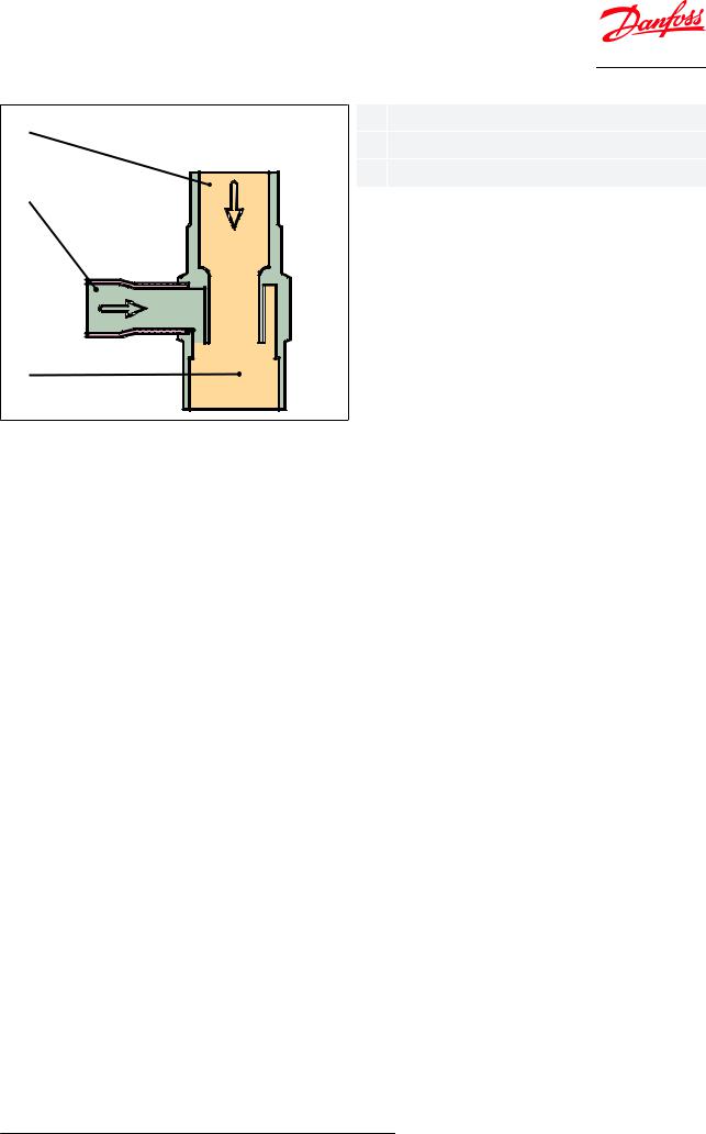
Figure 1: CPCE
4 |
<![if ! IE]> <![endif]>Danfoss 34N132.13.10 |
5 |
|
6 |
|
|
|
7 |
|
3 |
|
8 |
|
9 |
|
10 |
|
11 |
|
1 |
|
12 |
|
2 |
|
Hot gas bypass regulator, type CPCE is servo-operated.
1 |
Inlet |
|
|
2 |
Outlet |
|
|
3 |
Pilot pressure connection |
|
|
4 |
Protective cap |
|
|
5 |
Setting screw |
|
|
6 |
Main spring |
|
|
7 |
Diaphragm |
|
|
8 |
Pressure pin |
|
|
9 |
Pilot orifice |
|
|
10 |
Servo piston |
|
|
11 |
Pressure equalising hole |
|
|
12 |
Main orifice |
|
|
The diaphragm (7) is actuated on the upper side by the force developed by the spring (6) and on the lower side by the pilot pressure from (3). When the pilot pressure drops below the preset value, the throttling ball is forced away from the pilot orifice (9) by the spring which acts via the pressure pin (8).
The pressure over the servo piston (10) is then relieved. The differential pressure which is thus created moves the servo piston up and causes the regulator to open so that hot gas is able to flow to the suction side.
When the pilot pressure rises above the setting, the pilot orifice shuts off the evacuation from the space over the servo piston. Pressure then builds up again over the piston via the pressure equalising hole (11), thus closing the regulator.
© Danfoss | Climate Solutions | 2021.02 |
AI246086497130en-001501 | 2 |
Hot gas bypass regulator and Liquid gas mixer, type CPCE and LG
Figure 2: LG
1 |
2 |
| <![if ! IE]> <![endif]>Danfoss 69G39.12.10 |
3 |
1Liquid inlet
2Hot gas inlet
3Outlet
© Danfoss | Climate Solutions | 2021.02 |
AI246086497130en-001501 | 3 |

Hot gas bypass regulator and Liquid gas mixer, type CPCE and LG
Product speci€cations
Technical data
Table 1: Pressure range
Range |
Description |
|
Refrigerants |
R22, R1234ze *), R1270 *), R134a, R290 *), R404A, R407A, R407C, R407F, R448A, |
|
|
R449A, R450A, R452A, R507A, R513A, R600 *), |
|
|
R600a *) |
|
|
*) only LG 12-16 and LG 16-22 ; see more details in the note below the table |
|
Regulating range |
pe = 0 – 6 bar |
|
|
Factory setting = 0.4 bar |
|
Maximum working pressure |
PS/MWP = 28 bar |
|
Maximum test pressure |
Pe = 31 bar |
|
Maximum differential pressure |
Δp = 18 bar |
|
Maximum media temperature |
140 °C |
|
Minimum media temperature |
-50 °C |
|
|
|
This product is evaluated for R290, R600, R600a, R1234ze, R1270 by ignition source assessment in accordance with standard EN ISO80079-36. Flare connections are only approved for A1 and A2L refrigerants.
For complete list of approved refrigerants, visit www.products.danfoss.com and search for individual code numbers, where refrigerants are listed as part of technical data.
Sizing
For optimum performance, it is important to select a CPCE valve according to system conditions and application.
The following data must be used when sizing a CPCE valve:
•Refrigerant: HCFC, HFC and HC
•Minimum suction temperature: ts in [°C] / [bar]
•Compressor capacity at minimum suction temperature: Q1 in [kW]
•Evaporator load at minimum suction temperature: Q2 in [kW]
•Liquid temperature ahead of expansion valve: tl [°C]
•Reduction of suction temperature/suction pressure in [K]
•Connection type: flare or solder
•Connection size in [in] or [mm]
Selection
Example
When selecting the appropriate valve it may be necessary to convert the actual capacity using a correction factor. This is required when system conditions are different from table conditions.
The following examples illustrate how this is done.
•Refrigerant: R404A
•Minimum suction temperature: ts = -30 °C
•Compressor capacity at -30 °C, Q1= 80 kW
•Evaporator load at -30 °C, Q2 = 60 kW
•Liquid temperature ahead of expansion valve: tl = 40 °C
•Reduction of suction temperature/suction pressure = 5 K
•Connection type: solder
•Connection size = 1⁄2 in
Step 1
Determine the replacement capacity. This is done by taking the compressor capacity at minimum suction temperature Q1 minus evaporator load at minimum suction temperature Q2. Q1- Q2=80-60=20 kW
© Danfoss | Climate Solutions | 2021.02 |
AI246086497130en-001501 | 4 |
 Loading...