


Instructions |
|
|
|
|
|
AVP, AVP-F – PN 16,25/DN 15 – 50 |
|
|
|||
AVP (PN16) |
|
AVP-F (PN16) |
AVP (PN25) |
|
AVP-F (PN25) |
DN 15 - 32 |
|
DN 15 - 32 |
|
|
|
∆p = 0.05 - 0.5 |
|
∆p = 0.2 |
DN 15 - 50 |
|
DN 15 - 50 |
∆p = 0.2 - 1.0 |
|
∆p = 0.3 |
∆p = 0.2 - 1.0 |
|
∆p = 0.2 |
∆p = 0.8 - 1.6 |
|
∆p = 0.5 |
∆p = 0.3 - 2.0 |
|
∆p = 0.5 |
|
AVP (PN25) |
|
|
AVP-F (PN25) |
|
DN 15 - 25 |
DN 32 - 50 |
DN 15 - 50 |
DN 15 - 25 |
DN 32 - 50 |
DN 15 - 50 |
∆p = 0.2 - 1.0 |
∆p = 0.2 - 1.0 |
∆p = 0.2 - 1.0 |
∆p = 0.2 |
∆p = 0.2 |
∆p = 0.2 |
∆p = 0.3 - 2.0 |
∆p = 0.3 - 2.0 |
∆p = 0.3 - 2.0 |
∆p = 0.5 |
∆p = 0.5 |
∆p = 0.5 |
English |
Differential pressure controller |
www.danfoss.com |
Page 5 |
AVP, AVP-F |
|||
|
|
|
|
|
|
|
|
DANSK |
Differenstrykregulator |
www.danfoss.dk |
Side 6 |
AVP, AVP-F |
|||
|
|
|
|
DEUTSCH |
Differenzdruckregler |
www.danfoss.de |
Seite 7 |
AVP, AVP-F |
|||
|
|
|
|
ESPAÑOL |
Regulador de presión diferencial |
www.danfoss.es |
Página 8 |
AVP, AVP-F |
|||
|
|
|
|
Slovenščina |
Regulator diferenčnega tlaka |
www.danfoss.com |
Stran 9 |
AVP, AVP-F |
|||
|
|
|
|
Česky |
Regulátor diferenčního tlaku |
www.danfoss.com |
Strana 10 |
AVP, AVP-F |
|||
|
|
|
|
POLSKI |
Regulator różnicy ciśnień |
www.danfoss.pl |
Strona 11 |
AVP, AVP-F |
|||
|
|
|
|
РУССКИЙ |
Регулятор перепада давлений |
www.danfoss.ru |
Стр. 12 |
AVP, AVP-F |
|||
|
|
|
|
Lietuvių k. |
Slėgio perkryčio reguliatorius |
www.danfoss.com |
Puslapis 13 |
AVP, AVP-F |
|||
|
|
|
|
NEDERLANDS |
Differential pressure controller |
www.danfoss.nl |
Blz. 14 |
AVP, AVP-F |
|||
|
|
|
|
MAGYAR |
Nyomáskülönbség szabályozó |
www.danfoss.hu |
15. oldal |
AVP, AVP-F |
|||
|
|
|
|
Română |
Regulator de presiune diferenţială |
www.incalzire.danfoss.com |
Pagina 16 |
AVP, AVP-F |
73695010 DH-SMT/SI |
VI.DB.N3.8I © Danfoss 04/2009 |
1 |
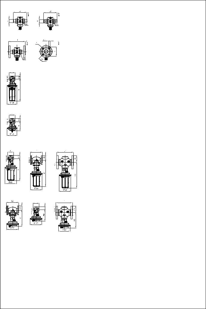
DN |
|
15 |
20 |
25 |
32 |
40 |
50 |
|
SW |
|
|
32 (G ¾A) |
41 (G 1A) |
50 (G 1¼A) |
63 (G 1¾A) |
70 (G 2A) |
82 (G 2½A) |
d |
|
|
21 |
26 |
33 |
42 |
47 |
60 |
R 1) |
|
|
1/2 |
3/4 |
1 |
11/4 |
- |
- |
L1 2) |
|
mm |
130 |
150 |
160 |
- |
- |
- |
L2 |
|
131 |
144 |
160 |
177 |
- |
- |
|
|
|
|||||||
L3 |
|
|
139 |
154 |
159 |
184 |
204 |
234 |
k |
|
|
65 |
75 |
85 |
100 |
110 |
125 |
d2 |
|
|
14 |
14 |
14 |
18 |
18 |
18 |
n |
|
4 |
4 |
4 |
4 |
4 |
4 |
|
AVP (PN16)
DN |
|
|
15 |
|
20 |
25 |
32 |
||||
|
|
|
|
|
|
|
|
|
|
|
|
|
|
flow |
|
return |
flow |
|
return |
flow |
return |
flow |
return |
|
|
|
|
|
|
|
|
|
|
|
|
L |
|
|
65 |
|
70 |
75 |
100 |
||||
H |
mm |
|
232 |
|
232 |
232 |
232 |
||||
H2 |
|
|
34 |
|
34 |
37 |
38 |
||||
AVP-F (PN16)
DN |
|
|
15 |
|
20 |
|
25 |
|
32 |
||||
|
|
flow |
|
return |
flow |
|
return |
flow |
|
return |
flow |
|
return |
|
|
|
|
|
|
|
|
|
|
|
|
|
|
L |
|
65 |
|
65 |
- |
|
70 |
- |
|
75 |
- |
|
100 |
H |
mm |
97 |
|
97 |
- |
|
97 |
- |
|
97 |
- |
|
97 |
H2 |
|
34 |
|
34 |
- |
|
34 |
- |
|
37 |
- |
|
38 |
AVP (PN25)
DN |
|
|
15 |
|
20 |
|
25 |
|
32 |
|
40 |
|
50 |
||||||
|
|
flow |
|
return |
flow |
|
return |
flow |
|
return |
flow |
|
return |
flow |
|
return |
flow |
|
return |
|
|
|
|
|
|
|
|
|
|
|
|
|
|
|
|
|
|||
L |
|
|
65 |
|
70 |
|
75 |
100 |
110 |
130 |
|||||||||
L1 |
|
130 |
150 |
160 |
180 |
200 |
230 |
||||||||||||
H |
mm |
233 |
|
220 |
233 |
|
220 |
233 |
|
220 |
275 |
|
261 |
275 |
|
261 |
275 |
|
261 |
H1 |
283 |
|
269 |
283 |
|
269 |
283 |
|
269 |
275 |
|
261 |
275 |
|
261 |
275 |
|
261 |
|
|
|
|
|
|
|
|
|||||||||||||
H2 |
|
|
34 |
|
34 |
|
37 |
|
62 |
|
62 |
|
62 |
||||||
H3 |
|
|
47 |
|
52 |
|
57 |
|
70 |
|
75 |
|
82 |
||||||
AVP-F (PN25)
DN |
|
|
15 |
|
20 |
|
25 |
|
32 |
|
40 |
|
50 |
||||||
|
|
|
|
|
|
|
|
|
|
|
|
|
|
|
|
|
|
|
|
|
|
flow |
|
return |
flow |
|
return |
flow |
|
return |
flow |
|
return |
flow |
|
return |
flow |
|
return |
|
|
|
|
|
|
|
|
|
|
|
|
|
|
|
|
|
|||
L |
|
|
65 |
|
70 |
|
75 |
100 |
110 |
130 |
|||||||||
L1 |
|
130 |
150 |
160 |
180 |
200 |
230 |
||||||||||||
H |
mm |
122 |
|
109 |
122 |
|
109 |
122 |
|
109 |
164 |
|
150 |
164 |
|
150 |
164 |
|
150 |
H1 |
172 |
|
158 |
172 |
|
158 |
172 |
|
158 |
164 |
|
150 |
164 |
|
150 |
164 |
|
150 |
|
|
|
|
|
|
|
|
|||||||||||||
H2 |
|
|
34 |
|
34 |
|
37 |
|
62 |
|
62 |
|
62 |
||||||
H3 |
|
|
47 |
|
52 |
|
57 |
|
70 |
|
75 |
|
82 |
||||||
73695010 DH-SMT/SI |
VI.DB.N3.8I © Danfoss 04/2009 |
2 |
|
|
|
|
|
||||
|
|
|
|
|
|
|
|
|
|
|
|
|
|
|
|
|
|
|
|
|
|
|
|
|
|
|
|
|
|
|
|
|
|
|
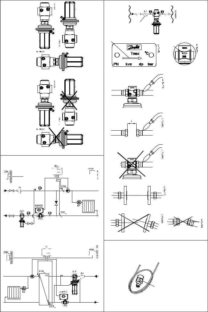
DN |
L (mm) |
15 |
69 |
20 |
74 |
25 |
79 |
32 |
104 |
40 |
114 |
50 |
134 |
R 1/8, R3/8, R 1/2
EN 10226
73695010 DH-SMT/SI |
VI.DB.N3.8I © Danfoss 04/2009 |
3 |

|
|
|
|
|
|
|
|
|
|
|
|
|
|
|
|
|
|
|
|
|
|
|
|
|
|
|
|
|
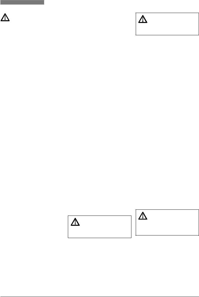
> 100 °C |
|
|
|
|
|
|
|
|
|
|
|
|
|
|
|
|
|
|
|
|
|
|
|
|
|
|
|
|
|
|
|
|
|
|
|
< 100 °C |
|
|
|
|
|
|
|
|
|
|
|
|
|
|
|
|
|
|
|
|
|
|
|
|
|
|
|
|
||
|
|
|
|
|
Δp = 1.0 - 4.5 bar |
|
|
|
|
|
|
|
|
|
|
|
|
|
|
|
|
|
|
|
|
|
|
|
|
|
|
|
|
|
|
|
|
|
|
|
|
|
|
|
|
|
|
73695010 DH-SMT/SI |
|
|
VI.DB.N3.8I © Danfoss 04/2009 |
4 |
|
ENGLISH
Safety Notes
Prior to assembly and commissioning to avoid injury of persons and damages of the devices, it is absolutely necessary to carefully read and observe these instructions.
Necessary assembly, start-up, and maintenance work must be performed only by qualified, trained and authorized personnel.
Prior to assembly and maintenance work on the controller, the system must be:
-depressurized,
-cooled down,
-emptied and
-cleaned.
Please comply with the instructions of the system manufacturer or system operator.
Definition of Application
The controller is used for pressure relief control of water and water glycol mixtures for heating, district heating and cooling systems.
The technical parameters on the product labels determine the use.
Assembly
Admissible Installation Positions
Medium temperatures up to 100 °C : - Can by installed in any position.
Medium temperatures > 100 °C :
-Installation permitted only in horizontal pipelines with the actuator oriented downwards.
Installation Location and
Installation Scheme
AVP (-F) return mounting
AVP (-F) flow mounting
Valve Installation
1.Clean pipeline system prior to assembly.
2.The installation of a strainer in front of the controller is strongly recommended .
3.Install pressure indicators in front of and behind the system part to be controlled.
4.Install valve
•The flow direction indicated on the product label or on the valve must be observed.
•The valve with mounted weldon tailpieces may only be spotwelded to the pipeline .
The weld-on tailpieces may be welded only without the valve and seals!
If these instructions are not observed, high welding temperatures
may destroy the seals.
•Flanges in the pipeline must be in parallel position and sealing surfaces must be clean and without any damage.
Tighten screws in flanges crosswise in 3 steps up to the maximum torque (50 Nm).
5.Caution:
Mechanical loads of the valve body by the pipelines are not permitted .
Impulse tube and seal pot mounting
•Which impulse tubes to use?
Use Impulse tube set AV or use following pipe:
Copper Ø 6 × 1 mm EN 12449
•Connection of impulse tube and seal pot
in the system
-Return mounting
-Flow mounting
•Connection to the pipeline
It is strongly recommended to install the impulse tube to the pipeline horizontallyor upwards .
This prevents dirt accumulation in the impulse tube and possible malfunction of the controller.
Connection downwards is not recommendable .
•Impulse Tube Mounting
1. Cut pipe perpendicularly to the pipe axis and smooth edges out .
2. Press impulse tube into the threaded joint up to its stop.
3. Tighten union nut Torque 14 Nm
Insulation
For medium temperatures up to 100 °C the pressure actuator may also be insulated.
Dimensions, Weights
(See page 2)
1)Conical ext. thread acc. to EN 10226-1
2)Flanges PN 25, acc. to EN 1092-2
Other flange dimensions - see table for tailpieces.
Leak and Pressure Tests
Pressure must be gradually increased at the +/- connection .
Non-compliance may cause damages at the actuator or the valve.
A pressure test of the entire system must be carried out in accordance with manufacturer’s instructions.
The maximum test pressure is: 1.5 × PN PN - see product label!
Putting out of operation
1.Slowly close shut-off devices in the flow pipeline.
2.Slowly close shut-off devices in the return pipeline.
Settings
Differential Pressure Setting
(not relevant at fixed setting version AVP-F)
The pressure setting range is indicated on the product label .
Procedure:
1.Start system, see section “Filling the system, first start-up“
Completely open all shut-off devices in the system.
2.Set flow rate on a motorised valve , on which differential pressure is controlled, to about 50 %.
3.Adjustment
Observe pressure indicators or/and alternatively see handle scale indication. Turning to the right (clockwise) increases the set-point (stressing the spring).
Turning to the left (counter clockwise)reduces the set-point (releasing the spring).
If the required differential pressure is not attained, a cause may be a too small pressure loss in the system.
Start-up
Filling the system, first start-up
1.Slowly open shut-off devices in the flow pipeline.
2.Slowly open shut-off devices in the return pipeline.
3.Slowly open shut-off devices in the flow pipeline.
4.Slowly open shut-off devices in the return pipeline.
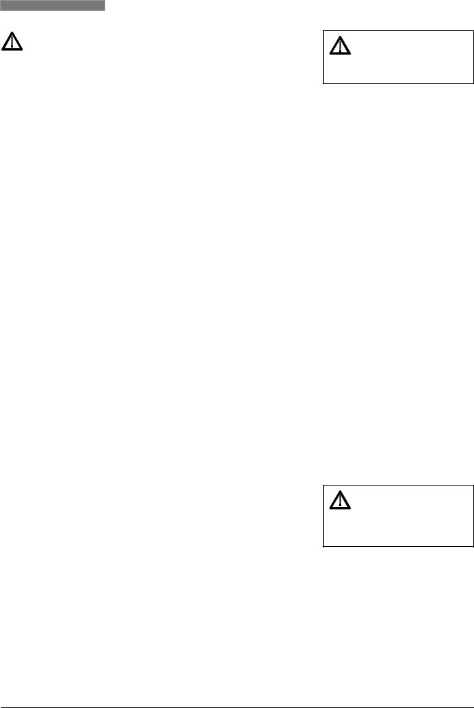
Seal
The set-point adjuster can be sealed by a seal wire , if necessary.
73695010 DH-SMT/SI |
VI.DB.N3.8I © Danfoss 04/2009 |
5 |
DANSK
Sikkerhedsnoter
Disse instruktioner SKAL læses omhyggeligt forud for montering og indkøring samt respekteres for at undgå skader på personer og udstyr.
Nødvendigt monterings-, opstartog vedligeholdelsesarbejde må kun udføres af faglært og autoriseret personale.
Forud for monteringsog vedligeholdelsesarbejde på regulatoren skal systemet være:
-trykløst,
-nedkølet,
-tømt og
-rengjort.
Systemproducentens eller -operatørens instruktioner skal overholdes.
Anvendelse
Regulatoren anvendes til differenstrykstyring af vand og vandglycolblandinger til varme-, fjernvarmeog kølesystemer.
De tekniske parametre på produktetiketterne fastlægger anvendelsen.
Montering
Tilladelige positioner
Medietemperaturer op til 100 °C : - Kan monteres i alle stillinger.
Medietemperaturer > 100 °C :
-Må kun installeres i vandrette rørledninger og med aktuatoren hængende nedad.
Indbygning
AVP (-F) montering i returledning AVP (-F) montering i flowledning
Valve Installation
1.Rengør rørledningssystemet før montering.
2.Det anbefales stærkt at installere et filter foran regulatoren .
3.nstaller manometre før og efter den systemdel, der skal kontrolleres.
4.Installer ventilen
•Den flowretning, der vises på produktetiketten eller på ventilen, skal respekteres .
•Ventilen med monterede svejsestudser må kun klemmes fast til rørledningen . Svejsestudserne må kun svejses uden ventil og pakninger!
Høje svejsetemperaturer kan ødelægge pakningerne, hvis disse instruktioner ikke overholdes.
•Flanger i rørledningen skal være placeret parallelt, og pakfladerne skal være rene og uden skader. Krydsspænd skruerne i flangerne i 3 trin til maks. moment (50 Nm).
5.Forsigtig:
Rørledningerne må ikke belaste ventilhuset mekanisk .
Montering af impulsledning
•Hvilke impulsledninger skal anvendes?
Anvend impulsledningssæt AV eller følgende rør:
Kobber Ø 6×1 mm EN 12449
•Tilslutning af impulsledning i systemet
-Montering i returledning
-Montering i flowledning
•Tilslutning til rørledning
Det anbefales stærkt at montere impulsledningen vandret eller opadpå rørledningen.
Dette forhindrer snavsophobning i impulsledningen samt evt. forringelse af regulatorfunktionen.
Det kan ikke anbefales at montere impulsledningen nedad .
•Montering af impulsledning
1. Skær røret over vinkelret på rørets akse og afglat enderne .
2. Pres impulsledningen ind til bunden af gevindsamlingen.
3. Spænd omløbermøtrikken . Moment 14 Nm
Isolering
Ved medietemperaturer op til 100 °C kan trykaktuatoren også være isoleret.
Dimensions, Weights
1)Konisk udv. gevind iht. EN 10226-1
2)Flanger PN 25 iht. EN 1092-2
Opstart
Påfyldning af systemet, første opstart
1.Åbn langsomt for afspærringsventilerneder muligvis sidder i impulsledningerne.
2.Åbn ventilerne i systemet.
3.Åbn langsomt for afsprærringsventilernei flowledningen.
4.Åbn langsomt for afsprærringsventilernei returledningen.
Lækageog trykprøvning
Trykket skal øges gradvist ved +/- tilslutningen .
Respekteres dette ikke, kan der opstå skader på aktuator eller ventil. Der skal udføres en trykprøvning af hele systemet i overensstemmelse med producentens instruktioner.
Det maksimale prøvetryk er: 1.5 × PN PN fremgår af produktetiketten
Stop af anlæg
1.Luk langsomt for afspærringsanordningerne i flowledningen.
2.Luk langsomt for afspærringsanordningerne i returledningen.
Indstilling af sætpunkter
Differenstrykindstilling
Indstillingsområdet for differenstrykket fremgår af produktetiketten .
Fremgangsmåde:
1.Se afsnittet “Påfyldning af systemet, første opstart” ved start af systemet. Åbn alle afspærringsanordninger i systemet helt.
2.Indstil flowet i en motorventil , hvor differenstrykket er kontrolleret, til ca. 50%.
3.Justering Hold øje med manometreneog/eller se alternativt på håndgrebets skalavisning.
Drejes til højre øges sætpunktet (fjederen spændes).
Drejes til venstre reduceres sætpunktet (fjederen udløses).
Hvis det ønskede differenstryk ikke opnås, kan det skyldes et for lille tryktab i systemet.
Plombering
Sætpunktsstilleskruen kan om nødvendigt forsegles med en plombe .
73695010 DH-SMT/SI |
VI.DB.N3.8I © Danfoss 04/2009 |
6 |
 Loading...