


Danfoss AMV 130(H), AMV 140(H), AME 130, AME 140, AME 130H Operating guide [cs]
...Operating Guide
AMV 130(H), AMV 140(H)
AME 130, 140
|
AMV + VZ 2 / VZL 2 |
AMV + VZ 3 / VZL 3 |
AMV + VZ 4 / VZL 4 |
AMV + AHQM |
AME 130H, 140H |
|
|
|
|
ENGLISH |
Actuators for three point control |
|
www.danfoss.com |
Page 4 |
AMV 130, AMV 140, AMV 130H, AMV 140H |
|
|||
|
|
|
||
DANSK |
Motorer til 3-punkts styring |
|
www.danfoss.dk |
Page 5 |
AMV 130, AMV 140, AMV 130H, AMV 140H |
|
|||
|
|
|
||
DEUTSCH |
Stellantriebe für 3-Pkt.- Schmittsignall |
|
www.danfoss.de |
Page 5 |
AMV 130, AMV 140, AMV 130H, AMV 140H |
|
|||
|
|
|
||
NEDERLANDS |
Servomotoren met 3-puntssturing |
|
www.danfoss.nl |
Page 6 |
AMV 130, AMV 140, AMV 130H, AMV 140H |
|
|||
|
|
|
||
ITALIANO |
Attuatore per il controllo a due punti |
|
www.danfoss.com |
Page 6 |
AMV 130, AMV 140, AMV 130H, AMV 140H |
|
|||
|
|
|
||
MAGYAR |
Szelepmozgatók hárompontos szabályozáshoz |
|
www.danfoss.com |
Page 7 |
AMV 130, AMV 140, AMV 130H, AMV 140H |
|
|||
|
|
|
||
ČESKY |
Servopohony s tříbodovým regulačním signálem |
www.danfoss.cz |
Page 7 |
|
AMV 130, AMV 140, AMV 130H, AMV 140H |
|
|||
|
|
|
||
POLSKI |
Siłowniki sterowane sygnałem 3-punktowym |
|
www.danfoss.pl |
Page 8 |
AMV 130, AMV 140, AMV 130H, AMV 140H |
|
|||
|
|
|
||
LIETUVIŲ K. |
Pavaros trijų padėčių valdymui |
|
www.danfoss.lt |
Page 8 |
AMV 130, AMV 140, AMV 130H, AMV 140H |
|
|||
|
|
|
||
LATVISKI |
Motori trīs punktu kontrolei |
|
www.danfoss.com |
Page 9 |
AMV 130, AMV 140, AMV 130H, AMV 140H |
|
|||
|
|
|
||
© Danfoss | 2017.07 |
VI.KU.L5.9O | 1 |
, AMV 140(H), AME 130, AME 140, AME 130H Operating guide")
AMV 130(H), AMV 140(H)
|
|
|
|
|
|
|
|
|
|
|
|
|
|
|
|
|
|
|
|
|
|
|
|
|
|
|
|
|
|
|
|
|
|
|
|
|
|
|
|
MAINTENANCE |
|
|
|
5-95 % RH |
|
|
|||
4 – 6 mm × 1 mm |
6 mm |
||||||||
FREE |
|
|
no condensing |
||||||
|
|
|
|
||||||
|
|
||||||||
30° 

30°
AMV 130/140, AMV 130H/140H - 24V


AMV 130/140, AMV 130H/140H - 230V
|
|
|
AMV 130, 140
6 mm
|
|
|
|
||
|
|
|
|
|
|


2 | © Danfoss | 2017.07 |
VI.KU.L5.9O |
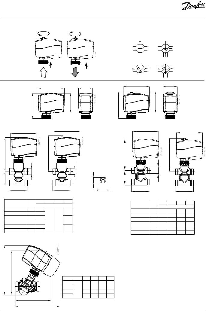
AMV 130(H), AMV 140(H)
AMV 130H, 140H
2 port |
3 or 4 port |
stem up
|
|
|
stem down |
|
|
|
|
||
|
92 |
50 |
92 |
50 |
| <![if ! IE]> <![endif]>88 |
<![if ! IE]> <![endif]>68 |
|
<![if ! IE]> <![endif]>94 |
<![if ! IE]> <![endif]>74 |
|
AMV 130, 140 |
|
|
AMV 130H, 140H |
92 |
92 |
|
|
92 |
|
|
|
92 |
| <![if ! IE]> <![endif]>H |
|
|
<![if ! IE]> <![endif]>1 |
|
|
|
<![if ! IE]> <![endif]>H |
|
|
<![if ! IE]> <![endif]>H |
|
|
|
|
<![if ! IE]> <![endif]>H |
|
|
|
|
|
|
|
|||
|
|
|
|
|
|
|
|
|
|
<![if ! IE]> <![endif]>1 |
|
|
|
<![if ! IE]> <![endif]>d |
|
|
|
<![if ! IE]> <![endif]>d |
|
|
<![if ! IE]> <![endif]>d |
|
|
|
|
| <![if ! IE]> <![endif]>h |
|
|
|
|
|
|
<![if ! IE]> <![endif]>1 |
|
|
|
|
|
|
|
|
|
<![if ! IE]> <![endif]>4.7 |
|
<![if ! IE]> <![endif]>h |
|
|
|
|
|
|
L |
|
|
|
|
L |
Ø5 |
L |
|
|
|
|
L |
|
|
|
|
|
|
|
|
|
|
|
|
|
AMV 130/140 + |
|
|
AMV 130H/140H + |
Stem extension |
AMV130/140 + VZL |
|
AMV130H/140H + VZL |
|||||
VZ (DN 15, 20) |
|
VZ 2, VZ 3, VZ 4 (DN 15, 20) |
plug |
|
||||||||
|
+ stem extension plug |
|
+ stem extension plug |
|||||||||
|
|
L |
H |
H1 |
h |
|
|
|||||
Valve type |
d |
|
Valve type |
d |
L |
H |
H1 |
h1 |
||||
|
|
mm |
|
|
||||||||
|
|
|
|
|
|
|
|
mm |
|
|||
VZ 2 / DN 15 |
G ½” |
65 |
|
|
|
|
|
|
|
|
|
|
|
|
26.5 |
|
VZL 2 DN 15 |
G ½” |
65 |
111 |
117 |
29.5 |
|||
VZ 2 / DN 20 |
G ¾” |
77 |
|
|
|
|||||||
|
|
|
|
VZL 2 DN 20* |
G ¾” |
77 |
117 |
123 |
34.0 |
|||
VZ 3 / DN 15 |
G ½” |
65 |
|
|
|
|
||||||
119 |
125 |
35 |
|
VZL 3 DN 15 |
G ½” |
65 |
111 |
117 |
35.0 |
|||
VZ 3 / DN 20 |
G ¾” |
77 |
|
|||||||||
|
|
|
|
VZL 3 DN 20 |
G ¾” |
77 |
117 |
123 |
35.0 |
|||
VZ 4 / DN 15 |
G ½” |
65 |
|
|
|
|
||||||
|
|
65 |
|
VZL 4 DN 15 |
G ½” |
65 |
111 |
117 |
51.0 |
|||
VZ 4 / DN 20 |
G ¾” |
77 |
|
|
|
|||||||
|
|
|
|
VZL 4 DN 20* |
G ¾” |
77 |
117 |
123 |
65.0 |
|||
|
|
|
|
|
|
|
||||||
* conex valves DN 20 - G 1 ¹/ ” 14 TPI
| <![if ! IE]> <![endif]>1 |
<![if ! IE]> <![endif]>H |
| <![if ! IE]> <![endif]>H |
|
|
<![if ! IE]> <![endif]>2 |
DN |
|
15 |
20 |
25 |
32 |
|
L1 |
|
118 |
125 |
141 |
160 |
|
L2 |
mm |
148 |
156 |
174 |
194 |
|
H1 |
168 |
178 |
196 |
216 |
||
|
||||||
H2 |
|
152 |
162 |
180 |
200 |
|
L1 |
|
|
|
|
|
|
L2 |
|
|
|
|
|
VI.KU.L5.9O |
© Danfoss | 2017.07 | 3 |
AMV 130(H), AMV 140(H)
ENGLISH
Safety Notes
To avoid injury of persons and
damages to the device, it is absolutely


 necessary to read and observe these instructions carefully.
Necessary assembly, start-up, and maintenance work must be performed by qualified and authorized personnel only.
Please comply with the instructions of the system manufacturer or system operator.
Do not remove the cover before the power supply is fully switched off.
Disposal instruction
This product should be dismantled and its components sorted, if possible, in various groups before recycling or disposal.
Always follow the local disposal regulations.
Mounting
In case of ship applications (on water) actuator should be mounted with the valve stem in either 30° above horizontal position or pointing upwards.
In case of building applications actuator should be mounted with the valve stem in either horizontal position or pointing upwards.The actuator is fixed to the valve body by means
of a ribbed nut which requires no tools for mounting. The ribbed nut should be tightened by hand.
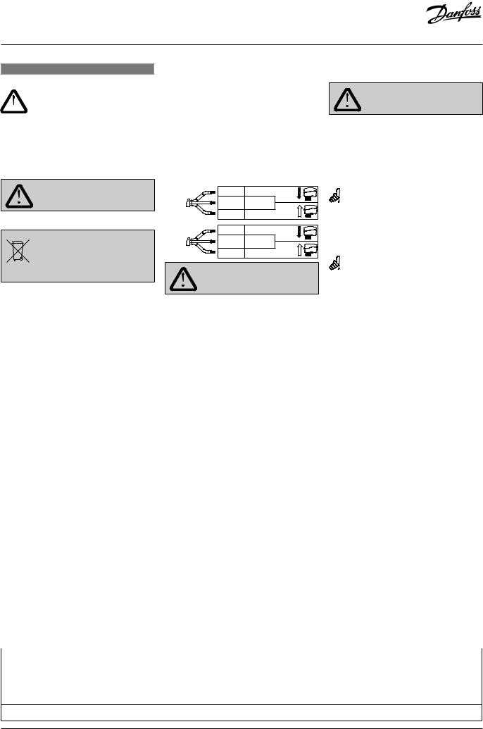
Wiring
|
Grey |
Stem down |
24 V |
Black |
Common |
|
Red |
Stem up |
|
Black |
Stem down |
230 V |
Blue |
Common |
|
Brown |
Stem up |
Do not touch anything on the PCB!
Lethal voltage!
Installation
1.Check the valve neck. The actuator should be in steam up position (factory setting). Ensure that the actuator is mounted securely on the valve body
2.Wire the actuator according to the wiring diagram
3.The direction of stem movement can be observed on the position indicator
Manual override
(for service purposes only)
Do not manually operate the drive if power is connected!
AMV 130, AMV 140
Remove cover
Insert the Allen key 6 into the spindle
Press and hold the button (on the bottom side of the actuator) during manual override
Pull out the toolReplace cover
Remark: A ‘click’ sound after energising the actuator means that the gear wheel has jumped into normal position.
AMV 130H, AMV 140H
Press and hold the button (on the bottom side of the actuator) during manual override.
Remark: A ‘click’ sound after energising the actuator means that the gear wheel has jumped into normal position.
Dimensions
Part Name |
|
|
|
Hazardous Substances Table/ |
|
||
Lead (Pb) |
Mercury (Hg) |
Cadmium (Cd) |
Hexavalent Chromium (Cr(VI)) |
Polybrominated biphenyls (PBB) |
Polybrominated diphenyl ethers (PBDE) |
||
|
|||||||
|
(Pb) |
(Hg) |
(Cd) |
(Cr(VI)) |
(PBB) |
(PBDE) |
|
Connecting nut |
X |
O |
O |
O |
O |
O |
|
|
X |
O |
O |
O |
O |
O |
|
O: Indicates that this hazardous substance contained in all of the homogeneous material for this part is below the limit requirement in GB/T 26572;
O: GB/T 26572
X: Indicates that this hazardous substance contained in at least one of the homogeneous material for this part is above the limit requirementw in GB/T 26572; X: GB/T 26572
4 | © Danfoss | 2017.07 |
VI.KU.L5.9O |
 Loading...