


Data sheet
Oil Motor Pump BFPM Controller
Application |
The BFPM range is a series of Danfoss oil pumps in |
BFPM Electronic Controller features: |
|
combination with a highly efficient permanent |
• One control for all BFPM motor pumps |
|
magnet motor, designed for use with small |
• Automatic recognition of connected BFPM |
|
domestic oil burners. |
motor pump |
|
|
• Built-in diagnostics |
|
BFPM Electronic Controller must be used for |
• Programmable for specific applications |
|
controlling the BFPM motor pumps (see separate |
• PWM signal |
|
data sheets for each BFPM oil motor pump). |
• Suitable for connection to electronic compound |
Connections |
Motor cable |
|
|
|
|
|
Signal cable |
|
|
Transducer signal cable |
|
|
Transducer cable |
|
|
Power cable |
|
Please notice:
•max. permitted cable length is 3000 mm.
•for EMC reason it might be necessary to add ferrite cores on the power supply cable and the motor cable.
•the controller must be mounted under a cover, where
tools are needed to get access. |
|
|
|
|
|
|
|
|
|
|
|
|
|
|
P1: |
Pressure relief valve/regulator |
R |
|
S |
|
|
|
||
S: |
Suction inlet G1/4 |
|
A |
V |
|
|
|
H |
|
R: |
Return outlet G1/4 |
|
|
|
|
|
|
||
E: |
Nozzle outlet G1/8 |
|
O |
M |
P: |
Pressure gauge port G1/8 |
|
P |
|
|
|
|||
V: |
Vacuum gauge port G1/8 |
|
|
P1 |
H: |
Filter |
|
|
PT |
|
|
|
||
PT: |
Pressure transmitter |
|
|
NC |
O: |
Constriction |
|
|
|
A: |
2-pipe screw |
|
|
|
|
|
|
|
E |
Technical Data |
|
|
|
Safety |
Galvanic isolated from high voltage side (supply voltage and motor) |
||
|
|||
|
to signal side |
||
|
|
||
|
|
|
|
|
Humidity |
Below 95% r.h. (non-condensing) |
|
|
|
|
|
|
Lifetime |
Min. 10 years operating, equal to 20,000 hours |
|
|
|
|
|
|
Operating temperatures |
0 to 60° C |
|
|
|
|
|
|
Storage temperature |
-20 to 60° C |
|
|
|
|
|
|
TÜV approval |
According to EN/IEC 60335-1 |
|
|
|
|
© Danfoss | 2019.05 |
VD.DK.P7.02| 1 |
Data sheet |
Oil Motor Pump BFPM Controller |
|
|
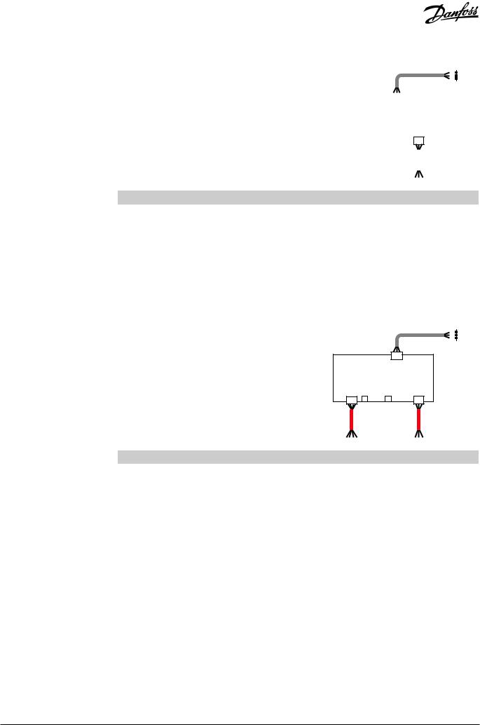
Operating Mode |
Fixed Speed |
|
1 |
|
|
2 |
|
|
|
3 |
|
|
|
||
Motor control box (MCB) |
|
|
|
|
|
|
|
|
|
|
|
|
|
|
|
|
|
|
|
|
||
Motor cable |
|
|
|
|
|
|
|
|
|
|
|
|
|
|
|
|
|
|
|
|
|
|
|
|
|
|
|
|
|
|
|
|
|
|
|
|
|
|
|
|
|
|
|
||
Power cable from Burner Control Box (BCB) |
|
|
|
|
|
|
|
|
|
|
|
|
|
|
|
|||||||
|
|
|
|
|
|
|
|
|
|
|
|
|
|
|
|
|
|
|
|
|
|
|
|
|
|
|
|
|
|
|
|
|
|
|
|
|
|
|
|
|
|
|
|
|
|
|
|
|
|
|
|
|
|
|
|
|
|
|
|
|
|
|
|
|
|
|
|
|
|
|
|
|
|
|
|
|
|
|
|
|
|
|
|
|
|
|
|||||
|
|
|
|
|
|
|
|
|
|
|
|
|
|
|
|
|
|
|
||||
|
|
|
|
|
|
|
|
|
|
|
|
|
|
|
|
|
|
|
|
|
||
|
|
|
|
|
|
|
|
|
|
|
|
|
|
|
|
3 2 1 |
|
|||||
|
|
|
|
|
|
|
|
|
|
|
|
|
|
|||||||||
Cable |
Terminal |
Colour |
Type |
Line |
Description |
|
|
|
Function |
|
|
|
Remarks |
|||||||||
|
|
|
|
|
|
|
|
|
|
|
|
|
|
|
|
|
|
|
|
|
||
Power |
1 |
brown |
|
|
L |
230 V, 50 Hz |
|
|
|
|
|
|
|
|
|
|
|
|
|
|
||
|
|
|
|
|
|
|
|
|
|
|
|
|
|
|
|
|
|
From Burner |
||||
2 |
yellow/green |
Input |
|
PE |
Protection |
|
Power supply |
|
|
|
||||||||||||
|
|
|
|
|
|
Control Box (BCB) |
||||||||||||||||
|
|
|
|
|
|
|
|
|
|
|
|
|
|
|
|
|
|
|||||
3 |
blue |
|
|
N |
0 |
|
|
|
|
|
|
|
|
|
|
|
|
|||||
|
|
|
|
|
|
|
|
|
|
|
|
|
|
|
|
|
|
|
||||
|
|
|
|
|
|
|
|
|
|
|
|
|
|
|
|
|
|
|
|
|
|
|
Motor |
1 |
brown |
|
|
W |
|
|
|
|
|
|
|
|
|
|
|
|
|
|
|
|
|
|
|
|
|
|
|
|
|
|
|
Motor power |
|
|
|
|
|
|
|
|||||
2 |
blue |
Internal |
|
V |
230 VAC |
|
|
|
|
|
|
|
|
|
||||||||
|
|
supply and drive |
|
|
|
|
|
|||||||||||||||
|
|
|
|
|
|
|
|
|
||||||||||||||
3 |
black |
|
|
U |
|
|
|
|
|
|
|
|
||||||||||
|
|
|
|
|
|
|
|
|
|
|
|
|
|
|
|
|
|
|
|
|||
|
|
|
|
|
|
|
|
|
|
|
|
|
|
|
|
|
|
|
|
|
|
|
Variable Speed
Motor control box (MCB)
Motor cable
Power cable from Electronic Control Box (ECB)
Control signal cable from Electronic Control Box (ECB)
|
|
|
1 |
|
|
2 |
|
|
|
3 |
|
|
|
||
|
|
|
|
|
|
|
|
4 3 2 1 |
3 2 1 |
Cable |
Terminal |
Colour |
Type |
Line |
Description |
Function |
Remarks |
|
|
|
|
|
|
|
|
|
|
|
1 |
white |
input |
+ |
4-12 VDC, |
Set point speed |
Optocoupled, |
|
Control |
2 |
yellow |
- |
50 Hz PWM |
galvanic isolated |
|||
|
|
|||||||
signal |
|
|
|
|
|
|
|
|
3 |
green |
|
+ |
Open collector, |
Feedback |
Optocoupled*, |
||
|
output |
|||||||
|
4 |
brown |
- |
50 Hz PWM |
speed |
RS 220 Ω, <25 mA |
||
|
|
|||||||
|
|
|
|
|
|
|
|
|
|
1 |
brown |
|
L |
230 V, 50 Hz |
|
|
|
Power |
|
|
|
|
|
|
From Electronic |
|
2 |
yellow/green |
Input |
PE |
Protection |
Power supply |
|||
|
Control Box (ECB) |
|||||||
|
|
|
|
|
|
|||
3 |
blue |
|
N |
0 |
|
|||
|
|
|
|
|||||
|
|
|
|
|
|
|
|
|
|
1 |
brown |
|
W |
|
Motor power |
|
|
Motor |
|
|
|
|
|
|
||
|
|
|
|
|
|
|||
2 |
blue |
Internal |
V |
230 VAC |
supply and |
|
||
|
|
|||||||
|
|
|
|
|
drive |
|
||
3 |
black |
|
U |
|
|
|||
|
|
|
|
|||||
|
|
|
|
|
||||
|
|
|
|
|
|
|
|
*SFH 6156-3
2 | © Danfoss | 2019.05 |
VD.DK.P7.02 |
 Loading...