


 Loading...
Dimensioning mass flow in hot gas defrost lines
Using Coolselector®2
Morten Juel Skovrup
2017-02-20
Version 1.32
Determining the dimensioning mass flow required for selecting the right pipes, fittings and components in hot gas defrost lines in Coolselector2.
Dimensioning mass flow in hot gas defrost lines
1 Introduction
Hot gas defrost calculations in Coolselector®2 are implemented for pump and gravity systems, i.e. systems where there is typically more than one evaporator.
Coolselector®2 supports 3 different types of hot gas defrost lines:
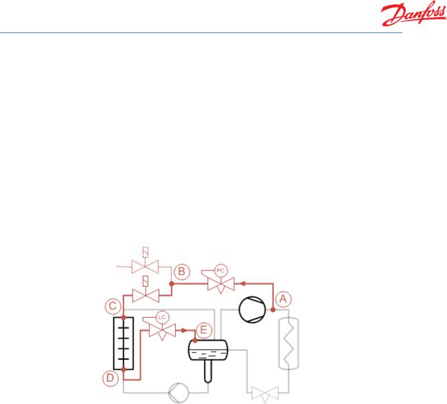
1.Main hot gas defrost line. Line that runs from compressor discharge to distribution point where line is split into separate lines for each evaporator (from A to B in diagram below).
2.Hot gas defrost line. Hot gas defrost supply line to each evaporator (from B to C in diagram below).
3.Hot gas defrost drain line. Line out of evaporator and back to separator (from D to E in diagram below).
The main functionality included in the three lines is often:
1.The main hot gas line is equipped with a control valve (ICS + CVC pilot) keeping the supply pressure at point B constant (“regulated hot gas”).
2.The hot gas defrost line is equipped with a solenoid valve, enabling start/stop of hot gas to the evaporator.
3.The defrost drain line is equipped with either:
a.A control valve (ICS + CVP pilot) keeping the defrost pressure constant – this is called “Pressure controlled drain”
b.A float valve, which simply lets condensed liquid generated during defrost back to the separator – this is called “Liquid drain”
2

Dimensioning mass flow in hot gas defrost lines
2 Inputs
To define the condition of the hot gas used for defrost the following inputs are needed:
Condensing temperature. The condensing temperature determines the pressure in point A in diagram below
Main hot gas supply temperature. The temperature in point A. It can be equal to the compressor discharge temperature, but normally it is somewhat reduced due to heat loss from the discharge line.
Reduced hot gas supply pressure. The pressure (or saturation temperature) corresponding to point B. This pressure is equal to the set point of the control valve in the main hot gas line.
Defrost pressure. The pressure (or saturation temperature) corresponding to point D. This pressure is equal to the set point of the control valve (for pressure controlled drain) in the defrost drain line.
Dimensioning quality. This will be treated separately below, but it is used to determine the density of the refrigerant flowing into the components placed in the defrost drain line – i.e. the dimensioning quality determines the position of point D.
Evaporating temperature. The evaporating temperature determines the pressure in point E
The location of the points is illustrated in the following log(p)-h diagram:
Note: The pressure in point C is not defined. It is calculated based on components selected in to the hot gas defrost line. Point C is illustrated as having same pressure as point D above, but that is not automatically the case.
Note: For liquid drain, the pressure in point D still needs to be defined (even though the pressure is not actually controlled). For liquid drain, the pressure in point D will in reality be a function of valves in the hot gas defrost line and the evaporator pressure drop. But for dimensioning purposes, a reasonable value a few degrees lower than point B will be sufficient.
3
Loading...