


OBJ_BUCH-1380-004.book Page 1 Wednesday, April 20, 2011 10:11 AM
WEU
Robert Bosch GmbH
Power Tools Division
70745 Leinfelden-Echterdingen
Germany
www.bosch-pt.com
2 609 140 838 (2011.05) T / 107 WEU
WEU
PMD 10
de |
Originalbetriebsanleitung |
da |
Original brugsanvisning |
en |
Original instructions |
sv |
Bruksanvisning i original |
fr |
Notice originale |
no |
Original driftsinstruks |
es |
Manual original |
fi |
Alkuperäiset ohjeet |
pt |
Manual original |
el |
Рсщфьфхрп пдзгйюн чсЮузт |
it |
Istruzioni originali |
tr |
Orijinal işletme talimat |
nl |
Oorspronkelijke |
ar |
ΔϴϠλϷ ϞϴϐθΘϟ ΕΎϤϴϠόΗ |
|
gebruiksaanwijzing |
|
|

OBJ_BUCH-1380-004.book Page 2 Wednesday, April 20, 2011 10:12 AM
2 |
Deutsch. . . . . . . . . . . . . . . . . . . . . . . . . . . . . . . . . . . . . . . . . . . . . . . . |
. Seite |
6 |
English. . . . . . . . . . . . . . . . . . . . . . . . . . . . . . . . . . . . . . . . . . . . . . . . . . |
.Page |
13 |
Français . . . . . . . . . . . . . . . . . . . . . . . . . . . . . . . . . . . . . . . . . . . . . . . . |
.Page |
23 |
Español . . . . . . . . . . . . . . . . . . . . . . . . . . . . . . . . . . . . . . . . . . . . . . . . |
Página |
30 |
Português . . . . . . . . . . . . . . . . . . . . . . . . . . . . . . . . . . . . . . . . . . . . . . |
Página |
38 |
Italiano . . . . . . . . . . . . . . . . . . . . . . . . . . . . . . . . . . . . . . . . . . . . . . . . |
Pagina |
45 |
Nederlands . . . . . . . . . . . . . . . . . . . . . . . . . . . . . . . . . . . . . . . . . . . . . |
Pagina |
53 |
Dansk . . . . . . . . . . . . . . . . . . . . . . . . . . . . . . . . . . . . . . . . . . . . . . . . . . |
. Side |
60 |
Svenska. . . . . . . . . . . . . . . . . . . . . . . . . . . . . . . . . . . . . . . . . . . . . . . . . |
. Sida |
66 |
Norsk. . . . . . . . . . . . . . . . . . . . . . . . . . . . . . . . . . . . . . . . . . . . . . . . . . . |
. Side |
72 |
Suomi . . . . . . . . . . . . . . . . . . . . . . . . . . . . . . . . . . . . . . . . . . . . . . . . . . |
. Sivu |
78 |
ЕллзнйкЬ . . . . . . . . . . . . . . . . . . . . . . . . . . . . . . . . . . . . . . . . . . . . . . . |
УелЯдб |
85 |
Türkçe . . . . . . . . . . . . . . . . . . . . . . . . . . . . . . . . . . . . . . . . . . . . . . . . . . |
Sayfa |
92 |
. . . . . . . . . . . . . . . . . . . . . . . . . . . . . . . . . . . . . . . . . . . . . . . . . |
ΔΤϔλ |
100 |
|
|
2 609 140 838 | (20.4.11) |
|
|
Bosch Power Tools |
|
|
||
|
|
|
|
|
|
|
|
|
|
|
|
|
|
|
|
|
|
|
|
|
|
|
|
|
|
|
|
|
|

OBJ_BUCH-1380-004.book Page 3 Wednesday, April 20, 2011 10:12 AM
| 3
|
a |
b |
c |
d |
a |
|
|
|
|
|
|
|
e |
|
|
|
|
|
|
|
l |
|
|
|
|
||
|
|
|
|
|||
|
|
|
|
|
|
f |
k |
|
|
|
|
g |
|
j |
|
|
|
|
h |
|
|
|
|
|
i |
|
|
9 
8 
7 
6 |
|
|
5 |
1 |
|
4 |
||
|
||
|
2 |
3 
PMD 10
|
|
Bosch Power Tools |
2 609 140 838 | (20.4.11) |
|
|
||||
|
|
|
|
|
|
|
|
|
|
|
|
|
|
|
|
|
|
|
|
|
|
|
|
|
|
|
|
|
|

OBJ_BUCH-1380-004.book Page 4 Wednesday, April 20, 2011 10:12 AM
4 |
10
8
11
12 |
10 |
13
|
|
2 609 140 838 | (20.4.11) |
|
|
Bosch Power Tools |
|
|
||
|
|
|
|
|
|
|
|
|
|
|
|
|
|
|
|
|
|
|
|
|
|
|
|
|
|
|
|
|
|

OBJ_BUCH-1380-004.book Page 5 Wednesday, April 20, 2011 10:12 AM
| 5
A
|
y |
10 |
|
x |
10 |
|
11 |
|
10 |
z |
10 |
|
|
10 |
x |
|
10 |
y
3x |
3x |
|
|
|
Bosch Power Tools |
2 609 140 838 | (20.4.11) |
|
|
||||
|
|
|
|
|
|
|
|
|
|
|
|
|
|
|
|
|
|
|
|
|
|
|
|
|
|
|
|
|
|

OBJ_BUCH-1380-004.book Page 6 Wednesday, April 20, 2011 10:12 AM
6 | Deutsch
Deutsch
Sicherheitshinweise
Sämtliche Anweisungen sind zu lesen und zu beachten.
BEWAHREN SIE DIESE ANWEISUNGEN GUT AUF.
fLassen Sie das Messwerkzeug von qualifiziertem Fachpersonal und nur mit Original-Ersatzteilen reparieren. Damit wird sichergestellt, dass die Sicherheit des Messwerkzeuges erhalten bleibt.
fArbeiten Sie mit dem Messwerkzeug nicht in explosionsgefährdeter Umgebung, in der sich brennbare Flüssigkeiten, Gase oder Stäube befinden.
Im Messwerkzeug können Funken erzeugt werden, die den Staub oder die Dämpfe entzünden.
fDas Messwerkzeug kann technologisch bedingt keine hundertprozentige Sicherheit garantieren. Um Gefahren auszuschließen, sichern Sie sich daher vor jedem Bohren, Sägen oder Fräsen in Wände, Decken oder Böden durch andere Informationsquellen wie Baupläne, Fotos aus der Bauphase etc. ab. Umwelteinflüsse, wie Luftfeuchtigkeit, oder Nähe zu anderen elektrischen Geräten können die Genauigkeit des Messwerkzeuges beeinträchtigen. Beschaffenheit und Zustand der Wände (z.B. Nässe, metallhaltige Baustoffe, leitfähige Tapeten, Dämmstoffe, Fliesen) sowie Anzahl, Art, Größe und Lage der Objekte können die Messergebnisse verfälschen.
Produktund Leistungsbeschreibung
Bestimmungsgemäßer Gebrauch
Das Messwerkzeug ist bestimmt zur Suche nach Metallen (Eisenund Nichteisenmetalle, z.B.Armierungseisen),Holzbalken sowie spannungsführenden Leitungen in Wänden, Decken und Fußböden.
Abgebildete Komponenten
Die Nummerierung der abgebildeten Komponenten bezieht sich auf die Darstellung des Messwerkzeugs auf der Grafikseite.
1Taste für Betriebsart „Trockenbau“
2Taste Displaybeleuchtung
3Batteriefachdeckel
4Taste Signalton
5Ein-Aus-Taste
6Taste für Betriebsart „Metall“
7Display
8Markierungsöffnung
9Leuchtring
10Gleiter
11Sensorbereich
12Typenschild
13Schutztasche
Abgebildetes oder beschriebenes Zubehör gehört nicht zum Standard-Lieferumfang.
Anzeigenelemente
aAnzeige der Objektart „spannungsführende Leitung“
bAnzeige der Warnfunktion
cSkala für „spannungsführende Leitung“
|
|
2 609 140 838 | (20.4.11) |
|
|
Bosch Power Tools |
|
|
||
|
|
|
|
|
|
|
|
|
|
|
|
|
|
|
|
|
|
|
|
|
|
|
|
|
|
|
|
|
|

OBJ_BUCH-1380-004.book Page 7 Wednesday, April 20, 2011 10:12 AM
Deutsch | 7
dAnzeige Temperaturüberwachung
eBatterie-Anzeige
fSkala für die Betriebsarten „Metall“ und „Trockenbau“
gAnzeige der Objektart „Nichtmetallobjekt“
hAnzeige der Betriebsart „Trockenbau“
iAnzeige der Objektart „magnetisches Metall“
jAnzeige der Betriebsart „Metall“
kAnzeige der Objektart „nicht magnetisches Metall“
lAnzeige für abgeschalteten Signalton
Technische Daten
Digitales Ortungsgerät |
PMD 10 |
Sachnummer |
3 603 F81 000 |
max. Erfassungstiefe* |
|
– Eisenmetalle |
100 mm |
– Nichteisenmetalle (Kupfer) |
80 mm |
– stromführende Leitungen 110–230 V |
|
(bei angelegter Spannung)** |
50 mm |
– Holz |
25 mm |
Abschaltautomatik nach ca. |
5 min |
Betriebstemperatur |
–10 °C...+50 °C |
Lagertemperatur |
–20 °C...+70 °C |
Batterie |
1 x 9 V 6LR61 |
Betriebsdauer ca. |
5 h |
Gewicht entsprechend EPTA-Procedure 01/2003 |
289 g |
|
|
*abhängig von Betriebsart, Material und Größe der Objekte sowie Material und Zustand des Untergrundes
**geringere Erfassungstiefe bei nicht spannungsführenden Leitungen
fDas Messergebnis kann hinsichtlich der Genauigkeit bei ungünstiger Beschaffenheit des Untergrundes schlechter ausfallen.
Bitte beachten Sie die Sachnummer auf dem Typenschild Ihres Messwerkzeugs, die Handelsbezeichnungen einzelner Messwerkzeuge können variieren.
Konformitätserklärung
Wir erklären in alleiniger Verantwortung, dass das unter „Technische Daten“ beschriebene Produkt mit den folgenden Normen oder normativen Dokumenten übereinstimmt: EN 61010-1:2010-10, EN 61326-1:2006-05,
EN 301489-3:2002-08, EN 301489-1:2008-04, EN 300330-1:2010-02, EN 300330-2:2010-02 gemäß den Bestimmungen der Richtlinien 2004/108/EG, 1999/5/EG.
Dr. Egbert Schneider |
Dr. Eckerhard Strötgen |
Senior Vice President |
Head of Product |
Engineering |
Certification |
Robert Bosch GmbH, Power Tools Division
D-70745 Leinfelden-Echterdingen
Leinfelden, 01.04.2011
|
|
Bosch Power Tools |
2 609 140 838 | (20.4.11) |
|
|
||||
|
|
|
|
|
|
|
|
|
|
|
|
|
|
|
|
|
|
|
|
|
|
|
|
|
|
|
|
|
|

OBJ_BUCH-1380-004.book Page 8 Wednesday, April 20, 2011 10:12 AM
8 | Deutsch
Montage
Batterie einsetzen/wechseln
Für den Betrieb des Messwerkzeugs wird die Verwendung von Alkali-Mangan- Batterien empfohlen.
Zum Öffnen des Batteriefachdeckels 3 schieben Sie diesen in Pfeilrichtung vom Batteriefach. Setzen Sie die mitgelieferte Batterie ein. Achten Sie dabei auf die richtige Polung entsprechend der Darstellung auf der Innenseite des Batteriefachs.
Die Batterie-Anzeige e zeigt immer den aktuellen Batteriestatus an:
–Batterie ist voll geladen
–Batterie hat 2/3 Kapazität oder weniger
–Batterie hat 1/3 Kapazität oder weniger
–Batterie bitte wechseln
fNehmen Sie die Batterie aus dem Messwerkzeug, wenn Sie es längere Zeit nicht benutzen. Die Batterie kann bei längerer Lagerung korrodieren oder sich selbst entladen.
Betrieb
fSchützen Sie das Messwerkzeug vor Nässe und direkter Sonneneinstrahlung.
fSetzen Sie das Messwerkzeug keinen extremen Temperaturen oder Temperaturschwankungen aus. Lassen Sie es bei größeren Temperaturschwankungen erst austemperieren, bevor Sie es einschalten. Bei extremen Temperaturen oder Temperaturschwankungen kann die Präzision des Messwerkzeugs und die Anzeige im Display beeinträchtigt werden.
fDas Benutzen oder der Betrieb von Sendeanlagen, wie z.B. WLAN, UMTS, Flugradar, Sendemasten oder Mikrowellen, in der näheren Umgebung kann die Messfunktion beeinflussen.
Inbetriebnahme
Ein-/Ausschalten
fStellen Sie vor dem Einschalten des Messwerkzeugs sicher, dass der Sensorbereich 11 nicht feucht ist. Reiben Sie das Messwerkzeug gegebenenfalls mit einem Tuch trocken.
fWar das Messwerkzeug einem starken Temperaturwechsel ausgesetzt, dann lassen Sie es vor dem Einschalten austemperieren.
Zum Einschalten des Messwerkzeugs drücken Sie die Ein-Aus-Taste 5.
Zum Ausschalten des Messwerkzeugs drücken Sie erneut die Ein-Aus-Taste 5.
Wird ca. 5 min lang keine Taste am Messwerkzeug gedrückt und werden keine Objekte detektiert, dann schaltet sich das Messwerkzeug zur Schonung der Batterie automatisch ab.
Displaybeleuchtung ein-/ausschalten
Mit der Taste Displaybeleuchtung 2 können Sie die Displaybeleuchtung einund ausschalten.
Signalton ein-/ausschalten
Mit der Taste Signalton 4 können Sie den Signalton einund ausschalten. Bei abgeschaltetem Signalton erscheint im Display die Anzeige l.
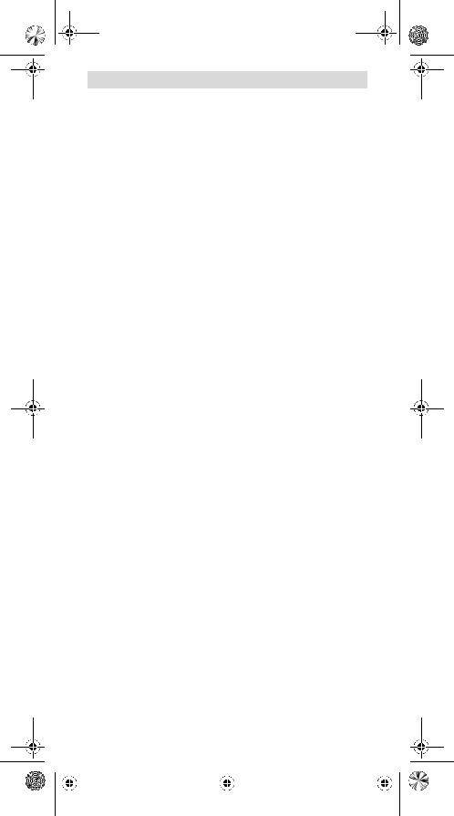
Funktionsweise (siehe Bild A)
Mit dem Messwerkzeug wird der Untergrund des Sensorbereiches 11 in Messrichtung z bis zur max. Erfassungstiefe (siehe „Technische Daten“) überprüft. Erkannt werden Objekte, die sich vom Material der Wand unterscheiden.
Bewegen Sie das Messwerkzeug stets geradlinig mit leichtem Druck über den Untergrund, ohne es abzuheben oder den Anpressdruck zu verändern.
|
|
2 609 140 838 | (20.4.11) |
|
|
Bosch Power Tools |
|
|
||
|
|
|
|
|
|
|
|
|
|
|
|
|
|
|
|
|
|
|
|
|
|
|
|
|
|
|
|
|
|

OBJ_BUCH-1380-004.book Page 9 Wednesday, April 20, 2011 10:12 AM
Deutsch | 9
Während der Messung müssen die Gleiter 10 immer Kontakt zum Untergrund haben.
Messvorgang
Setzen Sie das Messwerkzeug auf die zu untersuchende Oberfläche auf und bewegen Sie es in Richtung der x- und y-Achse. Nähert sich das Messwerkzeug einem Objekt, dann nimmt der Ausschlag in der Skala f zu und der Ring 9 leuchtet gelb, entfernt es sich von dem Objekt, dann nimmt der Ausschlag ab. Über der Mitte eines Objektes zeigt die Skala f den maximalen Ausschlag; der Ring 9 leuchtet rot und es ertönt ein Signalton. Bei kleinen oder tief liegenden Objekten kann der Ring 9 weiterhin gelb leuchten und der Signalton ausbleiben.
fBreitere Objekte werden nicht in der gesamten Breite durch den Leuchtring bzw. den Signalton angezeigt.
Um das Objekt genauer zu lokalisieren, bewegen Sie das Messwerkzeug wiederholt (3x) über dem Objekt hin und her.
Breitere Objekte im Untergrund sind durch einen andauernden, hohen Ausschlag der Skala f erkennbar. Der Ring 9 leuchtet gelb. Die Dauer des hohen Ausschlags entspricht in etwa der Objektbreite.
Werden sehr kleine oder tief liegende Objekte gesucht und die Skala f schlägt nur gering aus, bewegen Sie das Messwerkzeug wiederholt waagrecht (x-Achse) und senkrecht (y-Achse) über das Objekt.
fBevor Sie in die Wand bohren, sägen oder fräsen, sollten Sie sich noch durch andere Informationsquellen vor Gefahren sichern. Da die Messergebnisse durch Umgebungseinflüsse oder die Wandbeschaffenheit beeinflusst werden können, kann Gefahr bestehen, obwohl die Anzeige kein Objekt im Sensorbereich anzeigt (es ertönt kein Signalton und der Leuchtring 9 leuchtet grün).
Betriebsarten
Durch die Auswahl der Betriebsart erzielen Sie bestmögliche Messergebnisse. Die maximale Erfassungstiefe für Metallobjekte erreichen Sie in der Betriebsart „Metall“. Die maximale Erfassungstiefe für nicht metallische Objekte erreichen Sie in der Betriebsart „Trockenbau“. Spannungsführende Leitungen werden in jeder Betriebsart erkannt.
Trockenbau
Die Betriebsart „Trockenbau“ ist geeignet, um Holzund Metallobjekte sowie spannungsführende Leitungen in Trockenbauwänden zu finden.
Drücken Sie die Taste 1, um die Betriebsart „Trockenbau“ zu aktivieren. Die Anzeige h leuchtet auf. Sobald Sie das Messwerkzeug auf den zu untersuchenden Untergrund aufsetzen, leuchtet der Ring 9 grün und signalisiert Messbereitschaft.
In der Betriebsart „Trockenbau“ werden alle Objektarten gefunden und angezeigt:
–nicht metallisch, z.B. Holzbalken
– magnetisch, z.B. Armierungseisen
– nicht magnetisch, aber metallisch, z.B. Kupferrohr
–  spannungsführend, z.B. Stromleitung
Hinweise: In der Betriebsart „Trockenbau“ werden neben Holzund Metallobjekten sowie spannungsführenden Leitungen auch andere Objekte, z.B. wassergefüllte Kunststoffrohre angezeigt. Im Display 7 erscheint für diese Objekte die Anzeige g für Nichtmetallobjekte.
Nägel und Schrauben im Untergrund können dazu führen, dass ein Holzbalken im Display als Metallobjekt angezeigt wird.
Zeigt das Display 7 einen dauerhaften, hohen Ausschlag der Skala f und der Skala c, starten Sie den Messvorgang neu, indem Sie das Messwerkzeug an einer anderen Stelle auf den Untergrund aufsetzen.
|
|
Bosch Power Tools |
2 609 140 838 | (20.4.11) |
|
|
||||
|
|
|
|
|
|
|
|
|
|
|
|
|
|
|
|
|
|
|
|
|
|
|
|
|
|
|
|
|
|

OBJ_BUCH-1380-004.book Page 10 Wednesday, April 20, 2011 10:12 AM
10 | Deutsch
Signalisiert der Leuchtring 9 beim Aufsetzen auf den zu untersuchenden Untergrund keine Messbereitschaft, kann das Messwerkzeug den Untergrund nicht richtig erkennen.
–Drücken Sie so lange auf die Taste 1, bis der Leuchtring grün leuchtet.
–Wenn Sie anschließend einen neuen Messvorgang starten und das Messwerkzeug auf eine andere Wand aufsetzen, müssen Sie kurz die Taste 1 drücken.
–In seltenen Fällen kann das Messwerkzeug den Untergrund nicht erkennen, weil die Seite mit dem Sensorbereich 11 und dem Typenschild 12 verschmutzt ist. Säubern Sie das Messwerkzeug mit einem trockenen, weichen Tuch und starten Sie den Messvorgang neu.
Erscheint in der Betriebsart „Trockenbau“ an einer Messposition abwechselnd die Anzeige k (nicht magnetisches Metall) oder i (magnetisches Metall), sollten Sie in die Betriebsart „Metall“ wechseln, die besser geeignet ist, magnetische und nicht magnetische Objekte zu finden und zu unterscheiden.
Metall
Die Betriebsart „Metall“ ist geeignet, um magnetische und nicht magnetische Objekte sowie spannungsführende Leitungen zu finden (unabhängig von der Wandbeschaffenheit).
Drücken Sie die Taste 6, um die Betriebsart „Metall“ zu aktivieren. Der Leuchtring 9 leuchtet grün und die Anzeige j leuchtet auf.
Handelt es sich bei dem gefundenen metallischen Objekt um ein magnetisches Metall (z.B. Eisen), so wird im Display 7 das Symbol i angezeigt. Bei nicht magnetischen Metallen wird das Symbol k angezeigt. Für die Unterscheidung zwischen den Metallarten muss sich das Messwerkzeug über dem gefundenen Metallobjekt befinden (Ring 9 leuchtet rot).
Hinweis: Bei Baustahlmatten und Armierungen im untersuchten Untergrund wird über der gesamten Fläche ein Ausschlag in der Skala f angezeigt. Typischerweise wird bei Baustahlmatten direkt über den Eisenstäben im Display das Symbol i für magnetische Metalle angezeigt, zwischen den Eisenstäben erscheint das Symbol k für nicht magnetische Metalle.
Spannungsführende Leitungen suchen
Spannungsführende Leitungen werden in jeder Betriebsart angezeigt.
Wird eine spannungsführende Leitung gefunden, dann erscheint im Display 7 die Anzeige a und die Skala c schlägt aus. Bewegen Sie das Messwerkzeug wiederholt über die Fläche, um die spannungsführende Leitung genauer zu lokalisieren. Nach mehrmaligem Überfahren kann die spannungsführende Leitung sehr genau angezeigt werden. Ist das Messwerkzeug sehr nahe an der Leitung, dann blinkt der Leuchtring 9 rot und der Signalton ertönt mit schneller Tonfolge.
Hinweise:
–Spannungsführende Leitungen können leichter gefunden werden, wenn Stromverbraucher (z.B. Leuchten, Geräte) an der gesuchten Leitung angeschlossen und eingeschaltet werden.
–Unter bestimmten Bedingungen (wie z.B. hinter Metalloberflächen oder hinter Oberflächen mit hohem Wassergehalt) können spannungsführende Leitungen nicht sicher gefunden werden. Die Signalstärke einer spannungsführenden Leitung ist abhängig von der Lage der Kabel. Überprüfen Sie daher durch weitere Messungen in der näheren Umgebung oder andere Informationsquellen, ob eine spannungsführende Leitung vorhanden ist.
–Nicht spannungsführende Leitungen können Sie als Metallobjekte in der Betriebsart „Metall“ finden. Litzenkabel werden dabei nicht angezeigt (im Gegensatz zu Vollmaterialkabeln).
–Statische Elektrizität kann dazu führen, dass Ihnen Leitungen unpräzise, z.B. über einen großen Bereich, angezeigt werden. Um die Anzeige zu verbessern, legen Sie Ihre freie Hand neben dem Messwerkzeug flach auf die Wand, um die statische Elektrizität abzubauen.
|
|
2 609 140 838 | (20.4.11) |
|
|
Bosch Power Tools |
|
|
||
|
|
|
|
|
|
|
|
|
|
|
|
|
|
|
|
|
|
|
|
|
|
|
|
|
|
|
|
|
|
OBJ_BUCH-1380-004.book Page 11 Wednesday, April 20, 2011 10:12 AM
Deutsch | 11
Arbeitshinweise
fDie Messergebnisse können prinzipbedingt durch bestimmte Umgebungsbedingungen beeinträchtigt werden. Dazu gehören z.B. die Nähe von Geräten, die starke magnetische oder elektromagnetische Felder erzeugen, Nässe, metallhaltige Baumaterialien, alukaschierte Dämmstoffe sowie leitfähige Tapeten oder Fliesen. Beachten Sie deshalb vor dem Bohren, Sägen oder Fräsen in Wände, Decken oder Böden auch andere Informationsquellen (z.B. Baupläne).
Objekte markieren
Sie können gefundene Objekte bei Bedarf markieren. Messen Sie wie gewohnt. Haben Sie die Grenzen oder die Mitte eines Objektes gefunden, dann markieren Sie die gesuchte Stelle durch die Markierungsöffnung 8.
Temperaturüberwachung
Das Messwerkzeug ist mit einer Temperaturüberwachung ausgestattet, da eine exakte Messung nur möglich ist, solange die Temperatur im Innern des Messwerkzeugs konstant bleibt.
Leuchtet die Anzeige Temperaturüberwachung d auf, befindet sich das Messwerkzeug außerhalb der Betriebstemperatur oder war starken Temperaturschwankungen ausgesetzt. Schalten Sie das Messwerkzeug aus und lassen
Sie es erst austemperieren, bevor Sie es wieder einschalten.
Warnfunktion
Leuchtet im Display die Anzeige b auf, müssen Sie die Messung neu starten. Nehmen Sie das Messwerkzeug von der Wand und setzen Sie es an anderer Stelle auf den Untergrund.
Blinkt im Display 7 die Anzeige b, senden Sie das Messwerkzeug in der mitgelieferten Schutztasche an eine autorisierte Kundendienststelle.
Nachkalibrieren
Schlägt in der Betriebsart „Metall“ die Skala f dauerhaft aus, obwohl sich kein Objekt aus Metall in der Nähe des Messwerkzeugs befindet, kann das Messwerkzeug manuell nachkalibriert werden.
–Schalten Sie das Messwerkzeug aus.
–Entfernen Sie alle Objekte aus der Nähe des Messwerkzeugs, die angezeigt werden könnten, auch Armbanduhr oder Ringe aus Metall, und halten Sie das Messwerkzeug in die Luft.
Achten Sie darauf, dass die Batterie-Anzeige e noch mindestens 1/3 Kapazität anzeigt:
Halten Sie das Messwerkzeug so, dass das Typenschild 12 zum Boden zeigt. Vermeiden Sie helle Lichtquellen oder direkte Sonneneinstrahlung auf den Bereich 11 und 12, ohne diesen Bereich abzudecken.
–Drücken Sie gleichzeitig die Tasten 5 und 4 und halten Sie beide Tasten so lange gedrückt, bis der Leuchtring 9 rot leuchtet. Lassen Sie dann beide Tasten los.
–Verlief die Kalibrierung erfolgreich, startet das Messwerkzeug nach einigen Sekunden automatisch und ist wieder betriebsbereit.
Hinweis: Startet das Messwerkzeug nicht automatisch, wiederholen Sie das Nachkalibrieren. Sollte das Messwerkzeug dennoch nicht starten, senden Sie es bitte in der mitgelieferten Schutztasche an eine autorisierte Kundendienststelle.
Wartung und Service
Wartung und Reinigung
fÜberprüfen Sie das Messwerkzeug vor jedem Gebrauch. Bei sichtbaren Beschädigungen oder losen Teilen im Innern des Messwerkzeugs ist die sichere Funktion nicht mehr gewährleistet.
|
|
Bosch Power Tools |
2 609 140 838 | (20.4.11) |
|
|
||||
|
|
|
|
|
|
|
|
|
|
|
|
|
|
|
|
|
|
|
|
|
|
|
|
|
|
|
|
|
|

OBJ_BUCH-1380-004.book Page 12 Wednesday, April 20, 2011 10:12 AM
12 | Deutsch
Halten Sie das Messwerkzeug stets sauber und trocken, um gut und sicher zu arbeiten.
Tauchen Sie das Messwerkzeug nicht ins Wasser oder andere Flüssigkeiten.
Wischen Sie Verschmutzungen mit einem trockenen, weichen Tuch ab. Verwenden Sie keine Reinigungsoder Lösemittel.
Um die Messfunktion nicht zu beeinflussen, dürfen im Sensorbereich 11 auf der Vorderund Rückseite des Messwerkzeugs keine Aufkleber oder Schilder, insbesondere keine Schilder aus Metall, angebracht werden.
Entfernen Sie nicht die Gleiter 10 auf der Rückseite des Messwerkzeugs.
Sollte das Messwerkzeug trotz sorgfältiger Herstellungsund Prüfverfahren einmal ausfallen, ist die Reparatur von einer autorisierten Kundendienststelle für Bosch-Elektrowerkzeuge ausführen zu lassen. Öffnen Sie das Messwerkzeug nicht selbst.
Geben Sie bei allen Rückfragen und Ersatzteilbestellungen bitte unbedingt die 10-stellige Sachnummer laut Typenschild des Messwerkzeugs an.
Lagern und transportieren Sie das Messwerkzeug nur in der mitgelieferten Schutztasche.
Senden Sie im Reparaturfall das Messwerkzeug in der Schutztasche 13 ein.
Kundendienst und Kundenberatung
Der Kundendienst beantwortet Ihre Fragen zu Reparatur und Wartung Ihres Produkts sowie zu Ersatzteilen. Explosionszeichnungen und Informationen zu Ersatzteilen finden Sie auch unter:
www.bosch-pt.com
Das Bosch-Kundenberater-Team hilft Ihnen gerne bei Fragen zu Kauf, Anwendung und Einstellung von Produkten und Zubehören.
www.powertool-portal.de, das Internetportal für Handwerker und Heimwerker. www.ewbc.de, der Informations-Pool für Handwerk und Ausbildung.
Deutschland
Robert Bosch GmbH Servicezentrum Elektrowerkzeuge Zur Luhne 2
37589 Kalefeld – Willershausen
Tel. Kundendienst: +49 (1805) 70 74 10* Fax: +49 (1805) 70 74 11*
(*Festnetzpreis 14 ct/min, höchstens 42 ct/min aus Mobilfunknetzen) E-Mail: Servicezentrum.Elektrowerkzeuge@de.bosch.com
Tel. Kundenberatung: +49 (1803) 33 57 99
(Festnetzpreis 9 ct/min, höchstens 42 ct/min aus Mobilfunknetzen) Fax: +49 (711) 7 58 19 30
E-Mail: kundenberatung.ew@de.bosch.com
Österreich
Tel.: +43 (01) 7 97 22 20 10
Fax: +43 (01) 7 97 22 20 11
E-Mail: service.elektrowerkzeuge@at.bosch.com
Schweiz
Tel.: +41 (044) 8 47 15 11
Fax: +41 (044) 8 47 15 51
Luxemburg
Tel.: +32 (070) 22 55 65
Fax: +32 (070) 22 55 75
E-Mail: outillage.gereedschap@be.bosch.com
|
|
2 609 140 838 | (20.4.11) |
|
|
Bosch Power Tools |
|
|
||
|
|
|
|
|
|
|
|
|
|
|
|
|
|
|
|
|
|
|
|
|
|
|
|
|
|
|
|
|
|

OBJ_BUCH-1380-004.book Page 13 Wednesday, April 20, 2011 10:12 AM
English | 13
Entsorgung
Messwerkzeuge, Zubehör und Verpackungen sollen einer umweltgerechten Wiederverwertung zugeführt werden.
Werfen Sie Messwerkzeuge und Akkus/Batterien nicht in den Hausmüll!
Nur für EU-Länder:
Gemäß der europäischen Richtlinie 2002/96/EG müssen nicht mehr gebrauchsfähige Messwerkzeuge und gemäß der europäischen Richtlinie 2006/66/EG müssen defekte oder verbrauchte
Akkus/Batterien getrennt gesammelt und einer umweltgerechten Wiederverwendung zugeführt werden.
Nicht mehr gebrauchsfähige Akkus/Batterien können direkt abgegeben werden bei:
Deutschland
Recyclingzentrum Elektrowerkzeuge Osteroder Landstraße 3
37589 Kalefeld
Schweiz
Batrec AG
3752 Wimmis BE
Änderungen vorbehalten.
English
Safety Notes
Read and observe all instructions. SAVE THESE INSTRUC-
TIONS FOR FUTURE REFERENCE.
fHave the measuring tool repaired only through qualified specialists using original spare parts. This ensures that the safety of the measuring tool is maintained.
fDo not operate the measuring tool in explosive environments, such as in the presence of flammable liquids, gases or dusts. Sparks can be created in the measuring tool which may ignite the dust or fumes.
fFor technological reasons, the measuring tool cannot ensure 100 % certainty. To rule out hazards, safeguard yourself each time before drilling, sawing or routing in walls, ceilings or floors by means of other information sources, such as building plans, pictures from the construction phase, etc. Environmental influences, such as humidity or closeness to electrical devices, can influence the accuracy of the measuring tool. Surface quality and condition of the walls (e.g., moisture, metallic building materials, conductive wallpaper, insulation materials, tiles) as well as the amount, type, size and position of the objects can lead to faulty measuring results.
Product Description and Specifications
Intended Use
The measuring tool is intended for the detection of metals (ferrous and non-fer- rous metals, e.g., rebar), joists and “live” wires/conductors in walls, ceilings and floors.
|
|
Bosch Power Tools |
2 609 140 838 | (20.4.11) |
|
|
||||
|
|
|
|
|
|
|
|
|
|
|
|
|
|
|
|
|
|
|
|
|
|
|
|
|
|
|
|
|
|

OBJ_BUCH-1380-004.book Page 14 Wednesday, April 20, 2011 10:12 AM
14 | English
Product Features
The numbering of the product features shown refers to the illustration of the measuring tool on the graphic page.
1Button for operation mode “Drywall”
2Display-illumination button
3Battery lid
4Audio signal button
5On/Off button
6Button for operation mode “Metal”
7Display
8Marking hole
9Illuminated ring
10Contact pads
11Sensor area
12Type plate
13Protective pouch
The accessories illustrated or described are not included as standard delivery.
Display Elements
aIndication of the object type “Live conductor”
bWarning-function indicator
cMeasuring indicator of “Live conductor”
dTemperature control indicator
eBattery indicator
fMeasuring indicator for operation modes “Metal” and “Drywall”
gIndication of the object type “Non-metal object”
hOperating-mode indication “Drywall”
iIndication of the object type “Magnetic metal”
jOperating-mode indication “Metal”
kIndication of the object type “Non-magnetic metal”
lSwitched-off audio signal indicator
Technical Data
Digital Detector |
PMD 10 |
Article number |
3 603 F81 000 |
Maximum scanning depth* |
|
– Ferrous metals |
100 mm |
– Non-ferrous metals (copper) |
80 mm |
– Live conductors 110–230 V (voltage applied)** |
50 mm |
– Wood |
25 mm |
Automatic switch-off after approx. |
5 min |
Operating temperature |
–10 °C...+50 °C |
Storage temperature |
–20 °C...+70 °C |
Battery |
1 x 9 V 6LR61 |
Operating life time, approx. |
5 h |
Weight according to EPTA-Procedure 01/2003 |
289 g |
|
|
*depending on operating mode, material and size of the objects, as well as material and condition of the base material
**less scanning depth for wires/conductors that are not “live”
fIn terms of accuracy, the measuring result can be inferior in case of unfavourable surface quality of the base material.
Please observe the article number on the type plate of your measuring tool. The trade names of the individual measuring tools may vary.
|
|
2 609 140 838 | (20.4.11) |
|
|
Bosch Power Tools |
|
|
||
|
|
|
|
|
|
|
|
|
|
|
|
|
|
|
|
|
|
|
|
|
|
|
|
|
|
|
|
|
|

OBJ_BUCH-1380-004.book Page 15 Wednesday, April 20, 2011 10:12 AM
English | 15
Declaration of Conformity
We declare under our sole responsibility that the product described under “Technical Data” is in conformity with the following standards or standardization documents: EN 61010-1:2010-10, EN 61326-1:2006-05,
EN 301489-3:2002-08, EN 301489-1:2008-04, EN 300330-1:2010-02, EN 300330-2:2010-02 according to the provisions of the directives 2004/108/EC, 1999/5/EC.
Dr. Egbert Schneider
Senior Vice President Engineering
Robert Bosch GmbH, Power Tools Division
D-70745 Leinfelden-Echterdingen
Leinfelden, 01.04.2011
Assembly
Inserting/Replacing the Battery
Alkali-manganese batteries are recommended for the measuring tool.
To open the battery lid 3, slide it in the direction of the arrow away from the battery compartment. Insert the battery provided. When inserting, pay attention to the correct polarity according to the representation on the inside of the battery compartment.
The battery indicator e always indicates the current battery status:
– Battery fully charged
–Battery has 2/3 of its capacity or less
–Battery has 1/3 of its capacity or less
–Please change battery
fIf the measuring tool is not used for a long period of time, the battery must be removed. The battery can corrode or discharge itself over long periods.
Operation
fProtect the measuring tool against moisture and direct sun light.
fDo not subject the measuring tool to extreme temperatures or variations in temperature. In case of large variations in temperature, allow the measuring tool to adjust to the ambient temperature before switching it on. In case of extreme temperatures or variations in temperature, the accuracy of the measuring tool and the display indication can be impaired.
fUse or operation of transmitting systems, such as WLAN, UMTS, radar, transmitter masts or microwaves, in the close proximity can influence the measuring function.
Initial Operation
Switching On and Off
fBefore switching the measuring tool on, make sure that the sensor area 11 is not moist. If required, dry the measuring tool using a soft cloth.
fIf the measuring tool was subject to an extreme temperature change, allow it to adjust to the ambient temperature before switching on.
To switch on the measuring tool, press the On/Off button 5.
To switch off the measuring tool, press the On/Off button 5 again.
When no button on the measuring tool is pressed for approx. 5 minutes and when no objects are detected, the measuring tool automatically switches off to save the battery.
|
|
Bosch Power Tools |
2 609 140 838 | (20.4.11) |
|
|
||||
|
|
|
|
|
|
|
|
|
|
|
|
|
|
|
|
|
|
|
|
|
|
|
|
|
|
|
|
|
|

OBJ_BUCH-1380-004.book Page 16 Wednesday, April 20, 2011 10:12 AM
16 | English
Switching the Display Illumination On/Off
The display illumination can be switched on/off with display-illumination button 2.
Switching the Audio Signal On/Off
The audio signal can be switched on/off with the audio signal button 4. When the audio signal is switched off, indication l appears on the display.
Method of Operation (see figure A)
The measuring tool checks the base material of sensor area 11 in measurement direction z to the max. detection depth (see “Technical Data”). Objects are detected that differ from the material of the wall.
Always move the measuring tool in a straight line over the surface applying slight pressure, without lifting it off or changing the pressure. During measurement, the contact pads 10 must always have contact to the surface.
Measuring Procedure
Position the measuring tool on/against the surface being detected, and move it in direction of axis x and y. When the measuring tool comes closer to an object, the amplitude in measuring indicator f increases and ring 9 lights up yellow; when it is moved away from the object, the amplitude decreases. Measuring indicator f indicates the maximal amplitude above the centre of the object; ring 9 lights up red and an audio signal sounds. For small or deeply embedded objects, ring 9 can continue to light up yellow, while there is no audio signal.
fWide objects are not indicated by the illuminated ring or the audio signal throughout their complete width.
To localise the object more precisely, move the measuring tool repeatedly (3x) back and forth over the object.
Wider objects in the base material are detected through a continuous, high amplitude of measuring indicator f. Ring 9 lights up yellow. The duration of the high amplitude corresponds approximately with the object width.
When very small or deeply embedded objects are being sought and measuring indicator f reacts only slightly, move the measuring tool repeatedly over the object in horizontal (axis x) and vertical (axis y) direction.
fBefore drilling, sawing or routing into a wall, protect yourself against hazards by using other information sources. As the measuring results can be influenced through ambient conditions or the wall material, there may be a hazard even though the indicator does not indicate an object in the sensor range (no audio signal or beep and and the illuminated ring 9 lit green).
Operating Modes
The best measuring results are achieved through selection of the operating mode. The maximal detection depth for metal objects is achieved in the operating mode “Metal”. The maximal detection depth for non-metal objects is achieved in the operating mode “Drywall”. “Live” conductors are detected in any operating mode.
Drywall
The operating mode “Drywall” is suitable for detecting wood or metal objects as well as “live” conductors in drywalls.
Press button 1 to activate the operating mode “Drywall”. The indicator h lights up. As soon as the measuring tool is positioned against the base material to be detected, ring 9 lights up green and signals operational readiness.
In the operating mode “Drywall” all object types are detected and indicated:
–Non-metal, e.g. a wood beam
– Magnetic, e.g. reinforcing steel
– Non-magnetic, but metal, e.g. copper pipe
|
|
– |
“Live”, e.g. a “live” conductor |
|
|
|
|
||
|
|
|
|
|
|
|
|
|
|
|
|
2 609 140 838 | (20.4.11) |
|
|
Bosch Power Tools |
||||
|
|
|
|
|
|
|
|
|
|
|
|
|
|
|
|
|
|
|
|
|
|
|
|
|
|
|
|
|
|

OBJ_BUCH-1380-004.book Page 17 Wednesday, April 20, 2011 10:12 AM
English | 17
Notes: In the operating mode “Drywall”, other objects, apart from wood and metal objects and “live” conductors are also detected, such as plastic tubing filled with water. For such objects, the indication g for non-metal objects is indicated in display 7.
Nails and screws in the base material may cause a wooden beam to be indicated as a metal object on the display.
When display 7 indicates a continuously high amplitude of measuring indicator f and measuring indicator c, restart the measuring procedure again by positioning the measuring tool at a different location on the base material.
When the illuminated ring 9 does not signal operational readiness when positioning the measuring tool on the base material being detected, the measuring tool cannot properly detect the base material.
–Press and hold button 1 until the illuminated ring lights up green.
–When starting a new measuring procedure afterwards and positioning the measuring tool onto a different wall or surface, you must briefly press button 1.
–In rare cases, the measuring tool may not be able to detect the base material because the side with the sensor area 11 and the type plate 12 is soiled or dirty. Clean the measuring tool with a dry, soft cloth and restart the measuring procedure.
When the indication k (non-magnetic metal) or i (magnetic metal) is alternately displayed at a measuring position in operating mode “Drywall”, you should change to the operating mode “Metal”, which is better suitable for detecting and differentiating between magnetic and non-magnetic objects.
Metal
The operating mode “Metal” is suitable for detecting magnetic and non-magnet- ic objects as well as “live” conductors (independent of the wall material).
Press button 6 to activate the operating mode “Metal”. The illuminated ring 9 lights up green and indication j lights up.
When the detected metal object is of magnetic metal (e.g. iron), the symbol i is indicated on display 7. For non-magnetic metals, the symbol k is indicated. In order to differentiate between metal types, the measuring tool must be positioned above the detected metal object (ring 9 is lit red).
Note: For reinforcement steel mesh and steel in the examined base material, an amplitude is indicated over the complete surface of measuring indicator f. For reinforcement steel mesh, it is typical that the symbol i for magnetic metal is indicated on the display directly above the iron rods, whereas between the iron rods, the symbol k for non-magnetic metal will appear.
Scanning for “Live” Wires
“Live” conductors are indicated in any operating mode.
When a “live” conductor is detected, indication a appears on the display 7 and the measuring indicator c deflects. Move the measuring tool repeatedly over the area to localise the “live” conductor more precisely. After moving over the “live” conductor several times, it can be indicated very accurately. When the measuring tool is very close to the conductor, the illuminated ring 9 flashes red and the audio signal beeps swiftly.
Notes:
–“Live” conductors can be detected easier when power consumers (e.g. lamps, machines) are connected to the sought conductor and switched on.
–Under certain conditions (such as below metal surfaces or behind surfaces with high water content), “live” conductors cannot be securely detected. The signal strength of a “live” conductor depends on the position of the cable. Therefore, apply further measurements in close proximity or use other information sources to check if a “live” conductor exists.
|
|
Bosch Power Tools |
2 609 140 838 | (20.4.11) |
|
|
||||
|
|
|
|
|
|
|
|
|
|
|
|
|
|
|
|
|
|
|
|
|
|
|
|
|
|
|
|
|
|

OBJ_BUCH-1380-004.book Page 18 Wednesday, April 20, 2011 10:12 AM
18 | English
–Voltage-free conductors can be detected as metal objects in the operation mode “Metal”. This does not apply for stranded conductors (contrary to solid conductors or cable).
–Static electricity can lead to inaccurate indication of electric lines, e.g., over a large range. To improve the indication, place your free hand flat on the wall next to the measuring tool, in order to remove the static electricity.
Working Advice
fMeasuring values can be impaired through certain ambient conditions. These include, e.g., the proximity of other equipment that produce strong magnetic or electromagnetic fields, moisture, metallic building materials, foil-laminated insulation materials or conductive wallpaper or tiles. Therefore, please also observe other information sources (e.g. construction plans) before drilling, sawing or routing into walls, ceilings or floors.
Marking Objects
If required, detected objects can be marked. Perform a measurement as usual. Once you have found the boundaries or the centre of an object, mark the sought location through the marking hole 8.
Temperature Control
The measuring tool is equipped with a temperature control indicator, as accurate measurements are only possible as long as the temperature within the measuring tool remains constant.
When the temperature control indicator d lights up, the measuring tool is not within the operating temperature range or was subject to large variations in temperature. Switch the measuring tool off and allow it to adjust to the ambient temperature before switching it on again.
Warning Function
When indicator b lights up on the display, the measurement must be restarted. Remove the measuring tool from the wall and place it on the base material at a different location.
When indicator b flashes on display 7, send the measuring tool in the provided protective pouch to an authorised customer services agent.
Recalibration
When measuring indicator f indicates a continuously high amplitude in the operating mode “Metal”, even though there is no metal object near the measuring tool, the measuring tool can be manually recalibrated.
–Switch the measuring tool off.
–Remove all objects near the measuring tool that could be detected, including your wrist watch or rings made of metal, and hold the measuring tool up. Pay attention that battery indicator e indicates at least 1/3 capacity:
Hold the measuring tool in such a manner that the type plate 12 faces toward the ground. Avoid bright light sources or direct sunlight from shining on the area 11 and 12, without covering off this area.
–Press and hold buttons 5 and 4 until the illuminated ring 9 lights up red. Then release both buttons.
–When the calibration was successful, the measuring tool will automatically start after a few seconds, and will be ready for operation again.
Note: If the measuring tool does not automatically start, repeat the recalibration. If the measuring tool still does not start, send it in the provided protective pouch to an authorised customer services agent.
|
|
2 609 140 838 | (20.4.11) |
|
|
Bosch Power Tools |
|
|
||
|
|
|
|
|
|
|
|
|
|
|
|
|
|
|
|
|
|
|
|
|
|
|
|
|
|
|
|
|
|

OBJ_BUCH-1380-004.book Page 19 Wednesday, April 20, 2011 10:12 AM
English | 19
Maintenance and Service
Maintenance and Cleaning
fCheck the measuring tool each time before use. In case of visible damage or loose components inside the measuring tool, safe function can no longer be ensured.
Keep the measuring tool clean and dry at all times to ensure proper and safe working.
Do not immerse the measuring tool in water or other fluids.
Wipe away debris or contamination with a dry, soft cloth. Do not use cleaning agents or solvents.
In order not to affect the measuring function, decals/stickers or name plates, especially metal ones, may not be attached in the sensor area 11 on the front or back side of the measuring tool.
Do not remove the contact pads 10 on the backside of the measuring tool.
If the measuring tool should fail despite the care taken in manufacturing and testing procedures, repair should be carried out by an authorised after-sales service centre for Bosch power tools. Do not open the measuring tool yourself.
In all correspondence and spare parts orders, please always include the 10-digit article number given on the type plate of the measuring tool.
Store and transport the measuring tool only in the supplied protective pouch. In case of repairs, send in the measuring tool packed in its protective pouch 13.
After-sales Service and Customer Assistance
Our after-sales service responds to your questions concerning maintenance and repair of your product as well as spare parts. Exploded views and information on spare parts can also be found under:
www.bosch-pt.com
Our customer service representatives can answer your questions concerning possible applications and adjustment of products and accessories.
Great Britain
Robert Bosch Ltd. (B.S.C.) P.O. Box 98
Broadwater Park
North Orbital Road Denham
Uxbridge
UB 9 5HJ
Tel. Service: +44 (0844) 736 0109 Fax: +44 (0844) 736 0146
E-Mail: boschservicecentre@bosch.com
Ireland
Origo Ltd.
Unit 23 Magna Drive
Magna Business Park City West
Dublin 24
Tel. Service: +353 (01) 4 66 67 00 Fax: +353 (01) 4 66 68 88
|
|
Bosch Power Tools |
2 609 140 838 | (20.4.11) |
|
|
||||
|
|
|
|
|
|
|
|
|
|
|
|
|
|
|
|
|
|
|
|
|
|
|
|
|
|
|
|
|
|

OBJ_BUCH-1380-004.book Page 20 Wednesday, April 20, 2011 10:12 AM
20 | English
Australia, New Zealand and Pacific Islands
Robert Bosch Australia Pty. Ltd. Power Tools
Locked Bag 66
Clayton South VIC 3169
Customer Contact Center Inside Australia:
Phone: +61 (01300) 307 044 Fax: +61 (01300) 307 045 Inside New Zealand:
Phone: +64 (0800) 543 353 Fax: +64 (0800) 428 570 Outside AU and NZ:
Phone: +61 (03) 9541 5555 www.bosch.com.au
Republic of South Africa
Customer service
Hotline: +27 (011) 6 51 96 00
Gauteng – BSC Service Centre
35 Roper Street, New Centre Johannesburg
Tel.: +27 (011) 4 93 93 75
Fax: +27 (011) 4 93 01 26 E-Mail: bsctools@icon.co.za
KZN – BSC Service Centre
Unit E, Almar Centre
143 Crompton Street Pinetown
Tel.: +27 (031) 7 01 21 20
Fax: +27 (031) 7 01 24 46 E-Mail: bsc.dur@za.bosch.com
Western Cape – BSC Service Centre
Democracy Way, Prosperity Park Milnerton
Tel.: +27 (021) 5 51 25 77
Fax: +27 (021) 5 51 32 23 E-Mail: bsc@zsd.co.za
Bosch Headquarters
Midrand, Gauteng
Tel.: +27 (011) 6 51 96 00
Fax: +27 (011) 6 51 98 80 E-Mail: rbsa-hq.pts@za.bosch.com
People’s Republic of China
China Mainland
Bosch Power Tools (China) Co., Ltd. 567, Bin Kang Road
Bin Jiang District 310052 Hangzhou, P.R.China
Service Hotline: 400 826 8484 Fax: +86 571 8777 4502
E-Mail: contact.ptcn@cn.bosch.com www.bosch-pt.com.cn
|
|
2 609 140 838 | (20.4.11) |
|
|
Bosch Power Tools |
|
|
||
|
|
|
|
|
|
|
|
|
|
|
|
|
|
|
|
|
|
|
|
|
|
|
|
|
|
|
|
|
|
OBJ_BUCH-1380-004.book Page 21 Wednesday, April 20, 2011 10:12 AM
English | 21
HK and Macau Special Administrative Regions
Robert Bosch Hong Kong Co. Ltd. 21st Floor, 625 King’s Road North Point, Hong Kong
Customer Service Hotline: +852 (21) 02 02 35 Fax: +852 (25) 90 97 62
E-Mail: info@hk.bosch.com www.bosch-pt.com.hk
Indonesia
PT. Multi Tehaka
Kawasan Industri Pulogadung Jalan Rawa Gelam III No. 2 Jakarta 13930
Indonesia
Tel.: +62 (21) 46 83 25 22
Fax: +62 (21) 46 82 86 45/68 23 E-Mail: sales@multitehaka.co.id www.multitehaka.co.id
Philippines
Robert Bosch, Inc.
28th Floor Fort Legend Towers, 3rd Avenue corner 31st Street, Fort Bonifacio Global City, 1634 Taguig City, Philippines Tel.: +63 (2) 870 3871
Fax: +63 (2) 870 3870 matheus.contiero@ph.bosch.com www.bosch-pt.com.ph
Bosch Service Center: 9725-27 Kamagong Street San Antonio Village Makati City, Philippines Tel.: +63 (2) 899 9091 Fax: +63 (2) 897 6432
rosalie.dagdagan@ph.bosch.com
Malaysia
Robert Bosch (S.E.A.) Pte. Ltd. No. 8A, Jalan 13/6
G.P.O. Box 10818
46200 Petaling Jaya
Selangor, Malaysia
Tel.: +60 (3) 7966 3194
Fax: +60 (3) 7958 3838 cheehoe.on@my.bosch.com Toll-Free: 1800 880 188 www.bosch-pt.com.my
Thailand
Robert Bosch Ltd. Liberty Square Building No. 287, 11 Floor Silom Road, Bangrak Bangkok 10500
Tel.: +66 (2) 6 31 18 79 – 18 88 (10 lines) Fax: +66 (2) 2 38 47 83
Robert Bosch Ltd., P. O. Box 2054 Bangkok 10501, Thailand
|
|
Bosch Power Tools |
2 609 140 838 | (20.4.11) |
|
|
||||
|
|
|
|
|
|
|
|
|
|
|
|
|
|
|
|
|
|
|
|
|
|
|
|
|
|
|
|
|
|

 OBJ_BUCH-1380-004.book Page 22 Wednesday, April 20, 2011 10:12 AM
22 | English
Bosch Service – Training Centre 2869-2869/1 Soi Ban Kluay
Rama IV Road (near old Paknam Railway) Prakanong District
10110 Bangkok Thailand
Tel.: +66 (2) 6 71 78 00 – 4 Fax: +66 (2) 2 49 42 96 Fax: +66 (2) 2 49 52 99
Singapore
Robert Bosch (SEA) Pte. Ltd. 11 Bishan Street 21 Singapore 573943
Tel.: +65 6571 2772
Fax: +65 6350 5315 leongheng.leow@sg.bosch.com Toll-Free: 1800 333 8333 www.bosch-pt.com.sg
Vietnam
Robert Bosch Vietnam Co. Ltd 10/F, 194 Golden Building 473 Dien Bien Phu Street Ward 25, Binh Thanh District 84 Ho Chi Minh City
Vietnam
Tel.: +84 (8) 6258 3690 ext. 413 Fax: +84 (8) 6258 3692 hieu.lagia@vn.bosch.com www.bosch-pt.com
Disposal
Measuring tools, accessories and packaging should be sorted for environmentalfriendly recycling.
Do not dispose of measuring tools and batteries/rechargeable batteries into household waste!
Only for EC countries:
According to the European Guideline 2002/96/EC, measuring tools that are no longer usable, and according to the European
Guideline 2006/66/EC, defective or used battery packs/batteries, must be collected separately and disposed of in an envi-
ronmentally correct manner.
Batteries no longer suitable for use can be directly returned at:
Great Britain
Robert Bosch Ltd. (B.S.C.) P.O. Box 98
Broadwater Park
North Orbital Road Denham
Uxbridge
UB 9 5HJ
Tel. Service: +44 (0844) 736 0109 Fax: +44 (0844) 736 0146
E-Mail: boschservicecentre@bosch.com
Subject to change without notice.
|
|
2 609 140 838 | (20.4.11) |
|
|
Bosch Power Tools |
|
|
||
|
|
|
|
|
|
|
|
|
|
|
|
|
|
|
|
|
|
|
|
|
|
|
|
|
|
|
|
|
|

OBJ_BUCH-1380-004.book Page 23 Wednesday, April 20, 2011 10:12 AM
Français | 23
Français
Avertissements de sécurité
Il est impératif de lire et de respecter toutes les instructions.
GARDER PRECIEUSEMENT CES INSTRUCTIONS.
fNe faire réparer l’appareil de mesure que par une personne qualifiée et seulement avec des pièces de rechange d’origine. Ceci permet d’assurer la sécurité de l’appareil de mesure.
fNe pas faire fonctionner les appareils de mesure en atmosphère explosive, par exemple en présence de liquides inflammables, de gaz ou de poussières. L’appareil de mesure produit des étincelles qui peuvent enflammer les poussières ou les vapeurs.
fDe par sa conception technologique, l’appareil de mesure ne peut pas garantir une sécurité à 100 %. Afin d’exclure tout danger, prenez certaines précautions avant d’effectuer des travaux de perçage, de sciage ou de fraisage dans les murs, plafonds ou sols en consultant d’autres sources d’information telles que les plans de construction, les photos de la phase de construction etc. Les influences exercées par l’environnement telles que l’humidité de l’air ou la proximité d’autres appareils électriques peuvent entraver la précision de l’appareil de mesure. La structure ou l’état des murs (par ex. humidité, matériaux de construction métalliques, papiers peints conducteurs, matériaux isolants, carreaux) ainsi que le nombre, le type, la dimension et la position des objets peuvent fausser les résultats de mesure.
Description et performances du produit
Utilisation conforme
L’appareil de mesure est conçu pour détecter les métaux (métaux ferreux et nonferreux, tels que les fers d’armature), les poutres en bois ainsi que les conduites sous tension dans les murs, plafonds et sols.
Eléments de l’appareil
La numérotation des éléments de l’appareil se réfère à la représentation de l’appareil de mesure sur la page graphique.
1Touche mode « Cloison sèche »
2Touche d’éclairage de l’écran
3Couvercle du compartiment à piles
4Touche du signal sonore
5Touche Marche/Arrêt
6Touche mode « Métal »
7Ecran
8Ouverture de marquage
9Anneau luminescent
10Glisseur
11Zone de détection
12Plaque signalétique
13Etui de protection
Les accessoires décrits ou illustrés ne sont pas tous compris dans la fourniture d’origine.
|
|
Bosch Power Tools |
2 609 140 838 | (20.4.11) |
|
|
||||
|
|
|
|
|
|
|
|
|
|
|
|
|
|
|
|
|
|
|
|
|
|
|
|
|
|
|
|
|
|

OBJ_BUCH-1380-004.book Page 24 Wednesday, April 20, 2011 10:12 AM
24 | Français
Affichages
a « Gaine sous tension »
b Fonction d’avertissement
c Graduation « Conduite sous tension » d Contrôle de température
e Indicateur du niveau de charge des piles
f Graduation modes « Métal » et « Cloison sèche » g « Objet non métallique »
h Mode « Cloison sèche » i « Métaux ferreux »
j Mode « Métal »
k « Métaux non ferreux » l Signal acoustique éteint
Caractéristiques techniques
Détecteur numérique |
PMD 10 |
N° d’article |
3 603 F81 000 |
Profondeur max. de détection* |
|
– Métaux ferreux |
100 mm |
– Métaux non-ferreux (cuivre) |
80 mm |
– Conduites sous tension 110–230 V |
|
(tension appliquée)** |
50 mm |
– Bois |
25 mm |
Coupure automatique après env. |
5 min |
Température de fonctionnement |
–10 °C...+50 °C |
Température de stockage |
–20 °C...+70 °C |
Pile |
1 x 9 V 6LR61 |
Autonomie env. |
5 h |
Poids suivant EPTA-Procedure 01/2003 |
289 g |
|
|
*en fonction du mode de fonctionnement et de la taille des objets ainsi que du matériau et de l’état du support
**profondeur plus faible de détection pour les conduites sans tension
fDes propriétés défavorables de la surface pourraient entraver la précision du résultat de mesure.
Attention au numéro d’article se trouvant sur la plaque signalétique de l’appareil de mesure. Les désignations commerciales des différents appareils peuvent varier.
Déclaration de conformité
Nous déclarons sous notre propre responsabilité que le produit décrit sous « Caractéristiques techniques » est en conformité avec les normes ou documents normatifs suivants : EN 61010-1:2010-10, EN 61326-1:2006-05, EN 301489-3:2002-08, EN 301489-1:2008-04, EN 300330-1:2010-02,
EN 300330-2:2010-02 conformément aux termes des réglementations en vigueur 2004/108/CE, 1999/5/CE.
Dr. Egbert Schneider |
Dr. Eckerhard Strötgen |
Senior Vice President |
Head of Product |
Engineering |
Certification |
Robert Bosch GmbH, Power Tools Division
D-70745 Leinfelden-Echterdingen
Leinfelden, 01.04.2011
|
|
2 609 140 838 | (20.4.11) |
|
|
Bosch Power Tools |
|
|
||
|
|
|
|
|
|
|
|
|
|
|
|
|
|
|
|
|
|
|
|
|
|
|
|
|
|
|
|
|
|
OBJ_BUCH-1380-004.book Page 25 Wednesday, April 20, 2011 10:12 AM
Français | 25
Montage
Mise en place/changement de la pile
Pour le fonctionnement de l’appareil de mesure, nous recommandons d’utiliser des piles alcalines au manganèse.
Pour ouvrir le couvercle du compartiment à piles 3, poussez celui-ci dans le sens de la flèche. Introduisez la pile fournie. Veillez à respecter les polarités qui doivent correspondre à la figure se trouvant à l’intérieur du compartiment à piles.
L’indicateur du niveau de charge des piles e indique l’état actuel de charge de la pile :
– La pile est complètement chargée
– La pile a 2/3 ou moins de sa capacité
– La pile a 1/3 ou moins de sa capacité
– Remplacer la pile
fSortez les piles de l’appareil de mesure au cas où l’appareil ne serait pas utilisé pendant un temps prolongé. En cas de stockage prolongé, la pile peut se corroder ou se décharger.
Fonctionnement
fProtégez l’appareil de mesure contre l’humidité, ne l’exposez pas directement aux rayons du soleil.
fN’exposez pas l’appareil de mesure à des températures extrêmes ou de forts changements de température. S’il est exposé à d’importants changements de température, laissez-le revenir à la température ambiante avant de le remettre en marche. Des températures extrêmes ou de forts changements de température peuvent entraver la précision de l’appareil de mesure et de l’affichage.
fL’utilisation à proximité de stations d’émission tels que WLAN, UMTS, radar d’avions, antennes de transmission ou micro-ondes peut influencer la fonction de mesure.
Mise en service
Mise en marche/arrêt
fAvant de mettre en service l’appareil de mesure, assurez-vous que la zone de détection 11 n’est pas humide. Si nécessaire, séchez l’appareil de mesure à l’aide d’un chiffon.
fAu cas où l’appareil de mesure aurait été exposé à une forte différence de température, laissez-le équilibrer sa température avant de le mettre en service.
Pour mettre en marche l’appareil de mesure, appuyez sur la touche Marche/ Arrêt 5.
Pour arrêter l’appareil de mesure, appuyez à nouveau sur la touche Marche/ Arrêt 5.
Si l’on n’appuie sur aucune touche sur l’appareil de mesure pendant env. 5 min et qu’aucun objet n’est détecté, l’appareil s’arrête automatiquement afin de ménager la pile.
Activation/désactivation de l’éclairage de l’écran
Au moyen de la touche d’éclairage de l’écran 2, vous pouvez activer ou désactiver l’éclairage de l’écran.
Activation /désactivation du signal sonore
Au moyen de la touche du signal sonore 4, vous pouvez activer ou désactiver le signal sonore. Lorsque le signal sonore est désactivé, le symbole l est affiché.
|
|
Bosch Power Tools |
2 609 140 838 | (20.4.11) |
|
|
||||
|
|
|
|
|
|
|
|
|
|
|
|
|
|
|
|
|
|
|
|
|
|
|
|
|
|
|
|
|
|

OBJ_BUCH-1380-004.book Page 26 Wednesday, April 20, 2011 10:12 AM
26 | Français
Fonctionnement (voir figure A)
A l’aide de l’appareil de mesure, la surface de la zone de détection 11 est contrôlée dans le sens de la mesure z jusqu’à la profondeur de détection indiquée (voir « Caractéristiques techniques »). Les objets dont le matériau constitutif est différent de celui de la paroi sont détectés.
Déplacez l’appareil de mesure de manière uniforme sur la surface sans soulever l’appareil et sans modifier la pression appliquée. Les glisseurs 10 doivent toujours être en contact avec la surface pendant l’opération de mesure.
Mesure
Placez l’appareil de mesure sur la surface à examiner et déplacez-le vers l’axe x et y. Si l’appareil de mesure se rapproche d’un objet, l’oscillation sur la graduation f augmente et la bague 9 s’allume jaune ; si l’appareil s’éloigne d’un objet, l’oscillation diminue. L’oscillation de la graduation f est à son maximum quand l’appareil se trouve au dessus du centre d’un objet ; la bague 9 s’allume rouge et un signal sonore se fait entendre. Dans le cas de petits objets ou d’objets profondément enfouis, il est possible que la bague 9 reste allumée jaune et que le signal sonore ne se fasse pas entendre.
fLes objets larges ne sont pas affichés dans toute leur largeur par l’anneau luminescent ou le signal acoustique.
Pour une localisation précise de l’objet, déplacez l’appareil de mesure plusieurs fois (3 fois) au dessus de l’objet.
Les objets très larges se trouvant dans la surface se font reconnaître par une oscillation permanente élevée de la graduation f. La bague 9 s’allume jaune. La durée de cette forte oscillation correspond approximativement à la largeur des objets.
Si l’on recherche des objets très petits ou profondément enfoncés et que la graduation f n’oscille que faiblement, déplacez l’appareil de mesure plusieurs fois horizontalement (axe x) et verticalement (axe y) sur l’objet.
fIl est recommandé de consulter d’autres sources d’information avant de percer, scier ou fraiser dans le mur, afin d’éviter tout danger. Etant donné que les résultats de mesure peuvent être influencés par les effets de l’environnement ou par la structure du mur, on ne peut pas exclure la présence d’un danger même si aucun objet n’est affiché dans la zone de détection (aucun signal acoustique ne se fait entendre et l’anneau luminescent 9 est allumé vert).
Modes opératoires
La sélection du mode de fonctionnement vous permet d’obtenir de meilleurs résultats de mesure. La profondeur maximale de détection de métaux est obtenue en mode « métal ». La profondeur maximale de détection d’objets non métalliques est obtenue en mode « cloison sèche ». Les conduites sous tension sont détectées dans tous les modes.
Cloison sèche
Le mode « cloison sèche » est approprié pour détecter des objets en bois et des métaux ainsi que des conduites sous tension dans les cloisons sèches.
Appuyez sur la touche 1 pour activer le mode « cloison sèche ». L’affichage h s’allume. Dès que vous posez l’appareil de mesure sur la surface à examiner, l’anneau 9 s’allume en vert et signale que l’appareil est prêt à prendre des mesures.
Dans le mode « cloison sèche », tous les objets sont détectés et affichés :
– non métallique, p.ex. poutres en bois
– magnétique, p.ex. fers d’armature
– non magnétique, mais métallique, p.ex. tuyau en cuivre
–  sous tension, p.ex. conduite électrique
Remarques : Dans le mode « cloison sèche » non seulement des objets en bois et en métal et des conduites sous tension sont affichés, mais également d’autres objets tels que par ex. des tubes plastiques remplis d’eau. g pour objets non métalliques est affiché sur l’écran 7 pour ces objets.
|
|
2 609 140 838 | (20.4.11) |
|
|
Bosch Power Tools |
|
|
||
|
|
|
|
|
|
|
|
|
|
|
|
|
|
|
|
|
|
|
|
|
|
|
|
|
|
|
|
|
|

OBJ_BUCH-1380-004.book Page 27 Wednesday, April 20, 2011 10:12 AM
Français | 27
Une poutre en bois pourrait être affichée sur l’écran en tant qu’objet métallique, si des clous et des vis se trouvent dans la surface.
Si l’écran 7 affiche une oscillation permanente élevée des graduations f et c, redémarrez la mesure en plaçant l’appareil de mesure à un autre endroit sur la surface.
Si l’anneau luminescent 9 ne signale pas que l’appareil est prêt à prendre des mesures quand ce dernier est posé sur la surface à examiner, c’est que l’appareil de mesure ne peut pas bien détecter la surface.
–Appuyez sur la touche 1 jusqu’à ce que l’anneau luminescent devienne rouge.
–Si vous démarrez une autre mesure et posez l’appareil de mesure sur une autre paroi, appuyez brièvement sur la touche 1.
–Dans de rares cas, l’encrassement de la face sur laquelle se trouvent la zone de détection 11 et la plaque signalétique 12 empêche l’appareil de mesure de détecter la surface. Nettoyez l’appareil de mesure à l’aide d’un chiffon sec, doux, et redémarrez la mesure.
Si, en mode « cloison sèche » les affichages k (métal non magnétique) ou i (métal magnétique) apparaissent alternativement à un endroit de mesure, il est recommandé de commuter dans le mode « métal » qui est mieux approprié pour détecter et différencier entre les objets magnétiques et non-magnétiques.
Metal
Le mode « métal » est approprié pour détecter des objets magnétiques et non magnétiques ainsi que des conduites sous tension (indépendamment de la structure du mur).
Appuyez sur la touche 6 pour activer le mode « métal ». L’anneau luminescent 9 s’allume en vert et l’affichage j est allumé.
Si l’objet métallique détecté est un métal magnétique (par ex. fer), le symbole i est affiché sur l’écran 7. Pour les métaux non magnétiques, le symbole k est affiché. Pour différencier entre les deux types de métaux, l’appareil de mesure doit se trouver au-dessus de l’objet métallique détecté (l’anneau 9 s’allume rouge).
Note : Si des treillis soudés ou des armatures se trouvent derrière la surface examinée, des oscillations sont affichées sur l’ensemble de la surface dans la graduation f. Généralement, lors de la détection de treillis soudés, le symbole i pour métaux magnétiques apparaît sur l’affichage directement au dessus des barres de fer alors que le symbole k s’affiche entre les barres de fer en cas de détection de métaux non magnétiques.
Détection de conduites sous tension
Les conduites sous tension sont indiquées dans tous les modes.
Si une conduite sous tension est détectée, a est affiché sur l’écran 7 et la graduation c oscille. Déplacez l’appareil de mesure plusieurs fois sur la surface pour localiser avec précision la conduite sous tension. Après être passé plusieurs fois sur la conduite sous tension, cette dernière peut être affichée avec grande précision. Si l’appareil de mesure est très proche de la conduite, l’anneau luminescent 9 clignote en rouge et le signal sonore retentit avec une succession rapide de signaux sonores.
Remarques :
–Les conduites sous tension peuvent être détectées plus facilement, si les consommateurs de courant (par ex. lampes, appareils) sont connectés à la conduite et mis en service.
–Dans certaines conditions (par ex. derrière les surfaces métalliques ou les surfaces contenant beaucoup d’eau), il n’est pas toujours possible de détecter les conduites sous tension. La puissance du signal d’une conduite sous tension dépend de la position des câbles. Vérifiez en effectuant des mesures supplémentaires à proximité ou à l’aide d’autres sources d’information si une conduite sous tension est présente.
|
|
Bosch Power Tools |
2 609 140 838 | (20.4.11) |
|
|
||||
|
|
|
|
|
|
|
|
|
|
|
|
|
|
|
|
|
|
|
|
|
|
|
|
|
|
|
|
|
|

OBJ_BUCH-1380-004.book Page 28 Wednesday, April 20, 2011 10:12 AM
28 | Français
–Il est possible de détecter les conduites qui ne sont pas sous tension dans le mode « métal ». Les torons conducteurs ne seront toutefois pas indiqués (contrairement aux câbles pleins).
–L’électricité statique peut causer une détection imprécise de conduites, par ex. sur une grande zone. Pour améliorer la précision de l’affichage, placez votre main libre à proximité de l’appareil de mesure à plat sur le mur pour décharger l’électricité statique.
Instructions d’utilisation
fDe par la conception de l’appareil, les résultats de mesure peuvent être entravés par certaines conditions environnementales, tels que par ex. la proximité d’appareils qui génèrent de forts champs magnétiques ou électromagnétiques, l’humidité, les matériaux de construction contenant des métaux, les matériaux isolants métallisés ainsi que les papiers peints ou carreaux conducteurs. Avant le perçage, le sciage ou le fraisage dans les murs, plafonds ou sols, respecter également les autres sources d’information (par ex. plans de construction).
Marquage d’objets
Si nécessaire, marquez les objets détectés. Effectuez une mesure comme d’habitude. Si vous avez détecté les limites ou le centre d’un objet, marquez l’endroit cherché à travers l’ouverture de marquage 8.
Contrôle de température
L’appareil de mesure est équipé d’un contrôle de température étant donné qu’une mesure précise n’est possible que si la température reste constante à l’intérieur de l’appareil de mesure.
Si l’affichage de contrôle de température d s’allume, l’appareil de mesure se trouve en dehors de la température de service ou a été exposé à de forts changements de température. Eteignez l’appareil de mesure et laissez-le revenir à la température ambiante avant de le remettre en marche.
Fonction d’alerte
Si b est allumé sur l’écran, vous devez redémarrer la mesure. Retirez l’appareil de mesure du mur et placez-le à un autre endroit sur la surface.
Si b clignote sur l’écran 7, faites parvenir l’appareil de mesure dans son étui de protection à un centre de Service Après-Vente autorisé.
Calibrage
Si, en mode « métal », la graduation f oscille de façon permanente, bien qu’aucun objet métallique ne se trouve à proximité de l’appareil de mesure, vous pouvez recalibrer l’appareil de mesure manuellement.
–Eteignez l’appareil de mesure.
–Enlevez tous les objets se trouvant à proximité de l’appareil de mesure et qui pourraient être affichés, également montres ou anneaux en métal, et maintenez l’appareil de mesure en l’air.
Assurez-vous que l’affichage des piles e affiche encore 1/3 de capacité min. :
Maintenez l’appareil de mesure de sorte à ce que la plaque signalétique 12 soit orientée vers le sol. Evitez les sources claires de lumière ou un rayonnement solaire direct sur la zone 11 et 12, mais ne recouvrez toutefois pas cette zone.
–Maintenez appuyées simultanément les touches 5 et 4 jusqu’à ce que l’anneau luminescent 9 s’allume rouge. Puis relâchez les deux touches.
–Si le calibrage est réussi, l’appareil de mesure redémarre automatiquement au bout de quelques secondes et est de nouveau prêt à fonctionner.
Note : Si l’appareil de mesure ne redémarre pas automatiquement, répétez le processus de calibrage. Au cas où l’appareil de mesure ne redémarrerait toujours pas faites parvenir l’appareil de mesure dans son étui de protection à un centre de Service Après-Vente autorisé.
|
|
2 609 140 838 | (20.4.11) |
|
|
Bosch Power Tools |
|
|
||
|
|
|
|
|
|
|
|
|
|
|
|
|
|
|
|
|
|
|
|
|
|
|
|
|
|
|
|
|
|

OBJ_BUCH-1380-004.book Page 29 Wednesday, April 20, 2011 10:12 AM
Français | 29
Entretien et Service Après-Vente
Nettoyage et entretien
fContrôlez l’appareil de mesure avant chaque utilisation. En cas de dommages externes visibles ou d’éléments mobiles à l’intérieur, le bon fonctionnement de l’appareil de mesure ne peut plus être garanti.
Tenez toujours l’appareil de mesure propre afin d’assurer un travail impeccable et sûr.
N’immergez jamais l’appareil de mesure dans l’eau ou dans d’autres liquides.
Nettoyez l’appareil à l’aide d’un chiffon doux et sec. N’utilisez pas de détergents ou de solvants.
Afin de ne pas altérer la fonction de mesure, n’appliquez pas de plaquettes, en particulier de plaquettes en métal sur la zone de détection 11 se trouvant au dos ou sur la face avant de l’appareil de mesure.
N’enlevez pas les glisseurs 10 se trouvant sur le dos de l’appareil de mesure.
Si, malgré tous les soins apportés à la fabrication et au contrôle de l’appareil de mesure, celui-ci présentait un défaut, la réparation ne doit être confiée qu’à une station de Service Après-Vente agréée pour l’outillage Bosch. Ne démontez pas l’appareil de mesure vous-même.
Pour toute demande de renseignement ou commande de pièces de rechange, précisez-nous impérativement le numéro d’article à dix chiffres de l’appareil de mesure indiqué sur la plaque signalétique.
Ne transportez et rangez l’appareil de mesure que dans son étui de protection fourni avec l’appareil.
Au cas où l’appareil devrait être réparé, l’envoyer dans son étui de protection 13.
Service Après-Vente et Assistance Des Clients
Notre Service Après-Vente répond à vos questions concernant la réparation et l’entretien de votre produit et les pièces de rechange. Vous trouverez des vues éclatées ainsi que des informations concernant les pièces de rechange également sous :
www.bosch-pt.com
Les conseillers techniques Bosch sont à votre disposition pour répondre à vos questions concernant l’achat, l’utilisation et le réglage de vos produits et de leurs accessoires.
France
Vous êtes un utilisateur, contactez :
Le Service Clientèle Bosch Outillage Electroportatif Tel. : 0 811 36 01 22
(coût d’une communication locale) Fax : +33 (0) 1 49 45 47 67
E-Mail : contact.outillage-electroportatif@fr.bosch.com
Vous êtes un revendeur, contactez : Robert Bosch (France) S.A.S. Service Après-Vente Electroportatif 126, rue de Stalingrad
93705 DRANCY Cédex
Tel. : +33 (0) 1 43 11 90 06
Fax : +33 (0) 1 43 11 90 33
E-Mail : sav.outillage-electroportatif@fr.bosch.com
Belgique, Luxembourg
Tel. : +32 (070) 22 55 65
Fax : +32 (070) 22 55 75
E-Mail : outillage.gereedschap@be.bosch.com
|
|
Bosch Power Tools |
2 609 140 838 | (20.4.11) |
|
|
||||
|
|
|
|
|
|
|
|
|
|
|
|
|
|
|
|
|
|
|
|
|
|
|
|
|
|
|
|
|
|

OBJ_BUCH-1380-004.book Page 30 Wednesday, April 20, 2011 10:12 AM
30 | Español
Suisse
Tel. : +41 (044) 8 47 15 12
Fax : +41 (044) 8 47 15 52
Autres pays
Pour avoir des renseignements concernant la garantie, les travaux d’entretien ou de réparation ou les pièces de rechange, veuillez contacter votre détaillant spécialisé.
Elimination des déchets
Les appareils de mesure ainsi que leurs accessoires et emballages, doivent pouvoir suivre chacun une voie de recyclage appropriée.
Ne jetez pas les appareils de mesure et les accus/piles avec les ordures ménagères !
Seulement pour les pays de l’Union Européenne :
Conformément à la directive européenne 2002/96/CE, les appareils de mesure dont on ne peut plus se servir, et conformé-
ment à la directive européenne 2006/66/CE, les accus/piles usés ou défectueux doivent être isolés et suivre une voie de re-
cyclage appropriée.
Les accus/piles dont on ne peut plus se servir peuvent être déposés directement auprès de :
Suisse
Batrec AG
3752 Wimmis BE
Sous réserve de modifications.
Español
Instrucciones de seguridad
Deberán leerse y respetarse todas las instrucciones.
GUARDE ESTAS INSTRUCCIONES EN UN LUGAR SEGURO.
fÚnicamente haga reparar su aparato de medición por un profesional, empleando exclusivamente piezas de repuesto originales. Solamente así se mantiene la seguridad del aparato de medición.
fNo utilice el aparato de medición en un entorno con peligro de explosión, en el que se encuentren combustibles líquidos, gases o material en polvo. El aparato de medición puede producir chispas e inflamar los materiales en polvo o vapores.
fPor razones de tipo tecnológico el aparato de medición no puede garantizar una seguridad total. Para descartar situaciones de peligro, antes de taladrar, serrar o fresar en paredes, techos o suelos, consulte otras fuentes de información como planos de construcción, fotos de las fases de construcción, etc. Las influencias ambientales como la humedad del aire o la proximidad de otros aparatos eléctricos puede afectar a la precisión del aparato de medición. La naturaleza y estado de las paredes (p.ej. humedad, materiales de construcción que contengan metal, empapelados conductores de electricidad, aislantes, azulejos), así como la cantidad, tipo y posición de los objetos pueden desvirtuar los resultados en las mediciones.
|
|
2 609 140 838 | (20.4.11) |
|
|
Bosch Power Tools |
|
|
||
|
|
|
|
|
|
|
|
|
|
|
|
|
|
|
|
|
|
|
|
|
|
|
|
|
|
|
|
|
|
 Loading...