


D1260/D1260B
Installation Guide
EN Keypads

D1260/D1260B | Installation Guide | Trademarks
Trademarks
Microsoft®, Windows®, Windows NT® are either registered trademarks or trademarks of Microsoft Corporation in the United States and/or other countries.
CYCOLOY® is a registered trademark of General
Electric Company.
POLYLAC® is a registered trademark of CHI MEI
Industrial Corporation, LTD.
2 |
Bosch Security Systems | 12/15 | F01U071668-05 |

D1260/D1260B | Installation Guide | Contents
Contents |
|
|
1.0 |
Introduction............................................ |
4 |
1.1 |
Manual Organization.................................... |
4 |
1.2 |
Other Documentation Referenced ............ |
4 |
1.3 |
Documentation Conventions ..................... |
4 |
1.3.1 |
Type Styles Used in this Manual................ |
4 |
1.3.2Tips, Important Notes, Cautions and
|
Warnings........................................................ |
4 |
2.0 |
D1260/D1260B Overview ...................... |
5 |
2.1 |
Parts List ....................................................... |
6 |
2.2 |
Front Panel Features ................................... |
6 |
2.2.1 |
LCD Display .................................................. |
6 |
2.2.2 |
Keypad ........................................................... |
6 |
2.2.3 |
Keypad Function Keys ................................. |
6 |
2.2.4 |
Audible Tones ............................................... |
7 |
2.3 |
Internal Features.......................................... |
8 |
3.0 |
Installation .............................................. |
9 |
3.1 |
Mounting ....................................................... |
9 |
3.1.1 |
Location Recommendations....................... |
9 |
3.1.2 |
Mounting the Back Plate........................... |
10 |
3.2 |
Setting the DIP Switch.............................. |
10 |
3.3 |
Tamper Switch ........................................... |
10 |
3.4 |
Volume Control .......................................... |
11 |
3.5 |
Wiring........................................................... |
11 |
4.0 |
Programming the Control Panel.......... |
12 |
4.1 |
Enabling the D1260/D1260B Keypad ..... |
12 |
4.2 |
Programming Area Names ........................ |
13 |
4.3Programming Security Company
Information ................................................. |
13 |
4.3.1D9412x, D9412 and D9112 Control
Panels .......................................................... |
13 |
4.3.2D7412x, D7412, D7212x, and D7212
|
Control Panels............................................ |
14 |
4.4 |
99 + Enter “Setup?” Function.................. |
14 |
4.5 |
Programming Custom Functions............. |
15 |
4.6Adding “Service Walk” to D7412x/D7412/D7212x/D7212 Service
|
Menu ............................................................ |
15 |
5.0 |
Specifications....................................... |
17 |
Figures |
|
Figure 1: D1260/D1260B Front Panels.................. |
5 |
Figure 2: D1260/D1260B LCD Display................... |
6 |
Figure 3: D1260/D1260B Keypad ........................... |
6 |
Figure 4: D1260/D1260B with Back Plate |
|
Removed..................................................... |
8 |
Figure 5: D1260/D1260B Back Plate Mounting |
|
Options....................................................... |
9 |
Figure 6: D1260/D1260B DIP Switch................... |
10 |
Figure 7: Call for Service Display.......................... |
10 |
Figure 8: Increasing and Decreasing Volume ...... |
11 |
Figure 9: Bosch Control Panel to Keypad Flying |
|
Leads Wiring............................................ |
11 |
Figure 10: Plugging in Wire Connector to |
|
D1260/D1260B ....................................... |
11 |
Figure 11: Enhanced Command Center Prompt in |
|
RPS...................................................... |
12 |
Figure 12: Enable Display Revision Prompt in |
|
RPS...................................................... |
12 |
Figure 13: High Brightness Settings ..................... |
14 |
Figure 14: Low Brightness Settings ..................... |
14 |
Figure 15: Contrast Settings.................................. |
15 |
Tables |
|
Table 1: D1260/D1260B Installation Guide |
|
Organization .............................................. |
4 |
Table 2: Other Referenced Documentation......... |
4 |
Table 3: Parts List .................................................... |
6 |
Table 4: D1260/D1260B Dedicated Keys............. |
6 |
Table 5: Audible Tones............................................ |
7 |
Table 6: D1260/D1260B DIP Switch Settings... |
10 |
Table 7: Area/Point Numbers and Area Text ..... |
13 |
Table 8: D1260/D1260B Specifications ............. |
17 |
Bosch Security Systems | 12/15 | F01U071668-05 |
3 |
D1260/D1260B | Installation Guide | 1.0 Introduction
1.0 Introduction
This manual refers to the following control panels: B9512G, B8512G, D9412GV4, D7412GV4, D7212GV4, D9412GV3, D7412GV3, D7212GV3, D9412GV2, D7412GV2, D7212GV2, D9412G, D7412G, D7212G, D9412, D7412, D9112, and D7212. In the remainder of this manual, these control panels are referred collectively as “Bosch Control Panels.”
1.1Manual Organization
This manual is divided into four sections:
Table 1: D1260/D1260B Installation Guide
Organization
|
|
Sectio |
Description |
n |
|
1Introduction
2Overview
3Installation
4Programming the Control Panel
1.2Other Documentation Referenced
Throughout this manual, references are made to other documentation. Refer to Table 2 for the part numbers of the documentation that have additional information about the D1260/D1260B Keypads.
Table 2: Other Referenced Documentation
|
|
Name of document |
Part Number |
Security System User’s Guide |
4998122475 |
D7212G Program Entry Guide |
4998138538 |
D7212G Program Record Sheet |
4998138542 |
D9412G/D7412G Program Entry |
47775 |
Guide |
|
|
|
D9412G/D7412G Program Record |
47488 |
Sheet |
|
|
|
1.3Documentation Conventions
1.3.1Type Styles Used in this Manual
Bold text |
Usually indicates selections |
|
that you can use while |
|
programming your control |
|
panel or an important fact |
|
that you should note. |
Bold Italicized |
Denotes notes, cautions or |
|
warnings. |
Italicized text |
Refers you to a drawing, |
|
table, another section of this |
|
document, or another |
|
document. Also used |
|
symbolizes names for |
|
records that you will create. |
Courier New |
Indicates what can appear on |
Text |
the D1260/D1260B Keypads |
|
display. |
[CAPITALIZED |
Indicates a specific key to |
TEXT] |
press. |
|
Example: …press the |
|
[ENTER] key… |
|
Keys to press in sequence |
|
appears as [COMMAND] + |
|
[4] |
FileNew |
Describes a menu path in a |
|
Windows-based application. |
|
Example: …select FileNew |
|
to create a new… |
1.3.2Tips, Important Notes, Cautions and Warnings
Important Notes - Information for successful operation and programming. Also tips and shortcuts can be included here.
Caution - These caution the operator that physical damage to the program or equipment might occur.
Warning - These warn of the possibility of physical damage to the operator.
4 |
Bosch Security Systems | 12/15 | F01U071668-05 |

D1260/D1260B | Installation Guide | 2.0 D1260/D1260B Overview
2.0 D1260/D1260B
Overview
The D1260/D1260B Keypad is a SDI Bus compatible device used with the Bosch Control Panels with versions 6.40 or higher.
The D1260/D1260B features a keypad with keys that illuminate when pressed, a four-line by 20character display, and a built-in speaker that emits several distinct warning tones.
The control panel supplies all power and data requirements for the D1260/D1260B through a four-wire connection. Refer to the Current Rating Chart for Standby Battery Calculations provided in the approved applications compliance guide for the specific control panel used with the D1260/D1260B to determine if you need an additional power supply.
You can program the control panel to send messages identifying the supervised keypad that is in trouble to a central station receiver. To supervise a keypad, refer to the program entry guide specific to your control panel. If a keypad loses communication with the control panel for more than 15 sec, the keypad buzzes and Call for Service Contact us at: appears. Other keypads connected to the system show Service Keypad. The control panel transmits a serial device trouble report to the receiver. The keypad shows SDI FAILURE # if the Modem IIIa2 communication format is used or TROUBLE ZN D if the BFSK communication format is used. For more information, refer to the D6600 Computer Interface Manual (P/N: 4998122703).
Figure 1: D1260/D1260B Front Panels
3 |
D1260B |
|
|
1 |
2 |
|
|
|
|
|
|
|
4 |
3 |
2 |
4 |
|
D1260 |
|
|
|
3 |
1 |
3 


 #
#
|
|
|
|
|
|
|
|
|
|
|
|
|
|
|
|
|
|
|
|
|
4 |
|
4 |
|
|
|
|
|
|
|
|
|
|
|
|
|||
|
|
|
3- |
Soft keys (refer to Soft Keys in Section 2.2.3 |
||||||||
1 - |
LCD display |
|||||||||||
|
|
(refer to Section 2.2.1 LCD Display on |
|
Keypad Function Keys on page 6) |
||||||||
|
|
page 6) |
4 - |
Keypad function keys (refer to Section 2.2.3 |
||||||||
2 - |
Digital keypad |
|
Keypad Function Keys on page 6) |
|||||||||
|
|
(refer to Section 2.2.2 Keypad on page 6) |
|
|
|
|
|
|
|
|
|
|
|
|
|
|
|
|
|
|
|
|
|
|
|
|
Bosch Security Systems | 12/15 | F01U071668-05 |
|
|
|
|
|
5 |
|||||
D1260/D1260B | Installation Guide | 2.0 D1260/D1260B Overview
2.1Parts List
Table 3 lists the items included with a D1260, D1260BLK, D1260R and D1260B Keypads.
Table 3: |
Parts List |
|
|
|
|
|
|
|
|
|
|
Qty. |
Description |
Part Number |
|
|
|
|
|
1 |
CD with: |
4998122742B |
|
|
• |
D1260/D1260B Owner’s |
50410 |
|
|
Manual PDF |
|
|
• |
D1260/D1260B |
48101 |
|
|
Installation Guide PDF |
|
|
• |
Security System User’s |
4998122475 |
|
|
Guide PDF |
|
|
• |
Adobe Acrobat Reader |
40751C |
|
|
software |
|
1 |
Four-wire Flying Lead |
15-04298-000 |
|
|
Connector |
|
|
|
|
|
|
1 |
D1260/D1260B Installation |
48101 |
|
|
Guide |
|
|
1 |
Security System User’s Guide |
4998122475 |
|
|
|
|
|
3 |
Wall Anchor (8-10 x 7/8) |
15053 |
|
3 |
Screws #6x1.625PHC |
47817 |
|
|
|
|
|
2.2Front Panel Features
2.2.1LCD Display
The D1260/D1260B Keypad displays the status of the security system using words, numbers, and symbols in its liquid crystal display (LCD). When an event occurs where the control panel is notified, the D1260/D1260B shows each event in order of its priority.
Figure 2: D1260/D1260B LCD Display
For a listing and description of the D1260/D1260B displays and command functions, refer to the Security System User’s Guide (P/N: 4998122475).
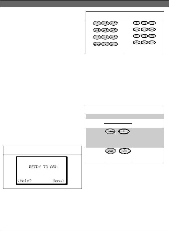
2.2.2Keypad
The D1260/D1260B Keypad features a digital keypad for entering user passcodes and executing system commands in the control panel.
Figure 3: D1260/D1260B Keypad |
|
|
# |
D1260 |
D1260B |
Please refer to the Security System User’s Guide
(P/N: 4998122475) for instructions on operating the system.
When a key is pressed, the D1260/D1260B emits a muted beep tone (refer to Section 2.2.4 Audible Tones on page 7) to indicate that the entry was accepted. The keypad lights and remains lit for 20 sec.
2.2.3Keypad Function Keys
The D1260/D1260B has ten numeric keys, two dedicated keys (Table 4) and eight soft keys, for controlling your system.
Table 4: D1260/D1260B Dedicated Keys
Key |
Picture |
Description |
|
|
D1260 |
D1260B |
|
COMMAND |
|
|
Use the [COMMAND] |
|
|
|
key in combination |
|
|
|
with one or two |
|
|
|
numeric keys to |
|
|
|
perform a function. |
ENTER |
# |
|
Use the [ENTER] key |
|
|
|
to complete the entry |
|
|
|
of your passcode at |
|
|
|
the keypad. |
Soft Keys
There are eight “soft” keys, four on either side of the display (Item 3 in Figure 1 on page 5), for accessing menu functions. They are called soft keys because, unlike the [COMMAND] and [ENTER] keys that have a defined function, they do different actions depending on the command or function accessed.
When a selection is available, an arrow (< or >) appears next to the key. To select the function, simply press the key next to it.
6 |
Bosch Security Systems | 12/15 | F01U071668-05 |
 Loading...