


P5V-VM
Ultra
User Guide
Motherboard

E2589
First Edition
September 2006
Copyright © 2006 ASUSTeK COMPUTER INC. All Rights Reserved.
No part of this manual, including the products and software described in it, may be reproduced, transmitted, transcribed, stored in a retrieval system, or translated into any language in any form or by any means, except documentation kept by the purchaser for backup purposes, without the express written permission of ASUSTeK COMPUTER INC. (“ASUS”).
Product warranty or service will not be extended if: (1) the product is repaired, modified or altered, unless such repair, modification of alteration is authorized in writing by ASUS; or (2) the serial number of the product is defaced or missing.
ASUS PROVIDES THIS MANUAL “AS IS” WITHOUT WARRANTY OF ANY KIND, EITHER EXPRESS OR IMPLIED, INCLUDING BUT NOT LIMITED TO THE IMPLIED WARRANTIES OR CONDITIONS OF MERCHANTABILITY OR FITNESS FOR A PARTICULAR PURPOSE. IN NO EVENT SHALL ASUS, ITS DIRECTORS, OFFICERS, EMPLOYEES OR AGENTS BE LIABLE FOR ANY INDIRECT, SPECIAL, INCIDENTAL, OR CONSEQUENTIAL DAMAGES (INCLUDING DAMAGES FOR LOSS OF PROFITS, LOSS OF BUSINESS, LOSS OF USE OR DATA, INTERRUPTION OF BUSINESS AND THE LIKE), EVEN IF ASUS HAS BEEN ADVISED OF THE POSSIBILITY OF SUCH DAMAGES ARISING FROM ANY DEFECT OR ERROR IN THIS MANUAL OR PRODUCT.
SPECIFICATIONS AND INFORMATION CONTAINED IN THIS MANUAL ARE FURNISHED FOR INFORMATIONAL USE ONLY, AND ARE SUBJECT TO CHANGE AT ANY TIME WITHOUT NOTICE, AND SHOULD NOT BE CONSTRUED AS A COMMITMENT BY ASUS. ASUS ASSUMES NO RESPONSIBILITY OR LIABILITY FOR ANY ERRORS OR INACCURACIES THAT MAY APPEAR IN THIS MANUAL, INCLUDING THE PRODUCTS AND SOFTWARE DESCRIBED IN IT.
Products and corporate names appearing in this manual may or may not be registered trademarks or copyrights of their respective companies, and are used only for identification or explanation and to the owners’ benefit, without intent to infringe.
ii

Contents
Notices............................................................................................ |
vi |
Safety information.......................................................................... |
vii |
P5V-VM Ultra specifications summary........................................... |
viii |
Chapter 1: Product Introduction
1.1 |
Welcome!............................................................................. |
1-2 |
|
1.2 |
Package contents................................................................. |
1-2 |
|
1.3 |
Special features.................................................................... |
1-2 |
|
|
1.3.1 |
Product highlights.................................................... |
1-2 |
|
1.3.2 |
ASUS unique features............................................. |
1-4 |
1.4 |
Before you proceed.............................................................. |
1-5 |
|
1.5 |
Motherboard overview.......................................................... |
1-6 |
|
|
1.5.1 |
Motherboard layout.................................................. |
1-6 |
|
1.5.2 |
Placement direction................................................. |
1-7 |
|
1.5.3 |
Screw holes............................................................. |
1-7 |
1.6 |
Central Processing Unit (CPU)............................................. |
1-8 |
|
|
1.6.1 |
Overview.................................................................. |
1-8 |
|
1.6.2 |
Installing the CPU.................................................... |
1-8 |
1.7 |
System memory................................................................. |
1-10 |
|
|
1.7.1 |
Overview................................................................ |
1-10 |
|
1.7.2 |
Memory configurations........................................... |
1-10 |
|
1.7.3 |
Installing a DIMM................................................... |
1-13 |
|
1.7.4 |
Removing a DIMM................................................. |
1-13 |
1.8 |
Expansion slots.................................................................. |
1-14 |
|
|
1.8.1 |
Installing an expansion card.................................. |
1-14 |
|
1.8.2 |
Configuring an expansion card.............................. |
1-14 |
|
1.8.3 |
PCI slots................................................................. |
1-16 |
|
1.8.4 |
PCI Express x 1 slot............................................... |
1-16 |
|
1.8.5 |
PCI Express x 16 slot............................................. |
1-16 |
1.9 |
Jumpers.............................................................................. |
1-17 |
|
1.10 |
Connectors......................................................................... |
1-19 |
|
|
1.10.1 |
Rear panel connectors........................................... |
1-19 |
|
1.10.2 |
Internal connectors................................................ |
1-20 |
iii

Contents
Chapter 2: BIOS Information
2.1 Managing and updating your BIOS...................................... |
2-2 |
||
|
2.1.1 Creating a bootable floppy disk................................ |
2-2 |
|
|
2.1.2 UsingAFUDOS to copy the current BIOS................ |
2-2 |
|
|
2.1.3 UsingAFUDOS to update the BIOS........................ |
2-3 |
|
|
2.1.4 Recovering the BIOS with CrashFree BIOS 2......... |
2-5 |
|
|
2.1.5 UsingASUS EZ Flash to update the BIOS.............. |
2-7 |
|
2.2 |
BIOS Setup program............................................................ |
2-8 |
|
|
2.2.1 |
BIOS menu screen................................................... |
2-9 |
|
2.2.2 |
Menu bar.................................................................. |
2-9 |
|
2.2.3 |
Navigation keys........................................................ |
2-9 |
|
2.2.4 |
Menu items............................................................ |
2-10 |
|
2.2.5 |
Sub-menu items..................................................... |
2-10 |
|
2.2.6 |
Configuration fields................................................ |
2-10 |
|
2.2.7 |
Pop-up window...................................................... |
2-10 |
|
2.2.8 |
Scroll bar................................................................ |
2-10 |
|
2.2.9 |
General help.......................................................... |
2-10 |
2.3 |
Main menu.......................................................................... |
2-11 |
|
|
2.3.1 |
System Time ......................................................... |
2-11 |
|
2.3.2 |
System Date ......................................................... |
2-11 |
|
2.3.3 |
Legacy DisketteA/B............................................... |
2-11 |
|
2.3.4 Primary,Secondary,Third,FourthIDEMaster/Slave.... |
2-12 |
|
|
2.3.5 |
IDE Configuration................................................... |
2-13 |
|
2.3.6 |
System Information................................................ |
2-14 |
2.4 |
Advanced menu................................................................. |
2-15 |
|
|
2.4.1 |
CPU Configuration................................................. |
2-15 |
|
2.4.2 |
Chipset................................................................... |
2-16 |
|
2.4.3 |
Onboard Devices Configuration............................. |
2-23 |
|
2.4.4 |
PCI PnP................................................................. |
2-24 |
2.5 |
Power menu....................................................................... |
2-25 |
|
|
2.5.1 |
ACPI 2.0 Support................................................... |
2-25 |
|
2.5.2 |
ACPIAPIC Support................................................ |
2-25 |
|
2.5.3 |
APM Configuration................................................. |
2-26 |
|
2.5.4 |
Hardware Monitor.................................................. |
2-28 |
2.6 |
Boot menu.......................................................................... |
2-29 |
|
|
2.6.1 |
Boot Device Priority............................................... |
2-30 |
|
2.6.2 |
Boot Settings Configuration................................... |
2-31 |
|
2.6.3 |
Security.................................................................. |
2-32 |
2.7 |
Exit menu........................................................................... |
2-33 |
|
iv

Contents
Chapter 3: Software Support
3.1 |
Installing an operating system.............................................. |
3-2 |
|
3.2 |
Support CD information........................................................ |
3-2 |
|
|
3.2.1 Running the support CD.......................................... |
3-2 |
|
|
3.2.2 |
Drivers menu............................................................ |
3-3 |
|
3.2.3 |
Utilities menu........................................................... |
3-3 |
|
3.2.4 |
Make disk menu....................................................... |
3-5 |
|
3.2.5 |
Manuals menu......................................................... |
3-5 |
|
3.2.6 |
ASUS contact information........................................ |
3-6 |

Notices
Federal Communications Commission Statement
This device complies with Part 15 of the FCC Rules. Operation is subject to the following two conditions:
•This device may not cause harmful interference, and
•This device must accept any interference received including interference that may cause undesired operation.
This equipment has been tested and found to comply with the limits for a
Class B digital device, pursuant to Part 15 of the FCC Rules. These limits are designed to provide reasonable protection against harmful interference in a residential installation. This equipment generates, uses and can radiate radio frequency energy and, if not installed and used in accordance with manufacturer’s instructions, may cause harmful interference to radio communications. However, there is no guarantee that interference will not occur in a particular installation. If this equipment does cause harmful interference to radio or television reception, which can be determined by turning the equipment off and on, the user is encouraged to try to correct the interference by one or more of the following measures:
•Reorient or relocate the receiving antenna.
•Increase the separation between the equipment and receiver.
•Connect the equipment to an outlet on a circuit different from that to which the receiver is connected.
•Consult the dealer or an experienced radio/TV technician for help.
To assure compliance with FCC regulations, use shielded cables to connect the monitor to the graphics card. Changes to this unit not expressly approved by the party responsible for compliance can void the user’s authority to operate this equipment.
Canadian Department of Communications Statement
This digital apparatus does not exceed the Class B limits for radio noise emissions from digital apparatus set out in the Radio Interference Regulations of the Canadian Department of Communications.
This class B digital apparatus complies with Canadian ICES-003.
vi
Safety Information
Electrical safety
•To prevent electrical shock hazard, disconnect the power cable from the electrical outlet before relocating the system.
•When adding or removing devices to or from the system, ensure that the power cables for the devices are unplugged before the signal cables are connected. If possible, disconnect all power cables from the existing system before you add a device.
•Before connecting or removing signal cables from the motherboard, ensure that all power cables are unplugged.
•Seek professional assistance before using an adapter or extension cord. These devices can interrupt the grounding circuit.
•Set your power supply to the correct voltage in your area. If you are not sure about the voltage of the electrical outlet you are using, contact your local power company.
•If the power supply is broken, do not try to fix it by yourself. Contact a qualified service technician or your retailer.
Operational safety
•Before installing the motherboard and adding devices on it, carefully read all the manuals that came with the package.
•Before using the product, make sure all cables are correctly connected and the power cables are not damaged. If you detect any damage, contact your dealer immediately.
•To avoid short circuits, keep paper clips, screws, and staples away from connectors, slots, sockets, and circuitry.
•Avoid dust, humidity, and temperature extremes. Do not place the product in any area where it can get wet.
•Place the product on a stable surface.
•If you encounter technical problems with the product, contact a qualified service technician or your retailer.
The symbol of the crossed out wheeled bin indicates that the product (electrical and electronic equipment) should not be placed in municipal waste. Check local regulations for disposal of electronic products.
vii

P5V-VM Ultra Specifications Summary
CPU
Chipset
System bus
Memory
Expansion slots
Storage
Audio
LAN USB 2.0
Rear panel I/O ports
Internal I/O connectors
LGA775 socket for Intel® Core™2 Extreme / Core™2 Duo /
Pentium® D / Pentium® 4 / Celeron® D Processors
Compatible with Intel® 06/05B/05A processors Supports Enhanced Intel SpeedStep® Technology (EIST),
and Intel® Hyper-Threading Technology
Northbridge: VIA P4M890
Southbridge: VIAVT8237A 1066/800/533 MHz
2 x 240-pin DDR2 DIMM sockets for up to 2 GB unbuffered DDR2 533 DRAM memory
1 x PCI Express x16 slot for discrete graphics card 1 x PCI Express x1
2 x PCI slots
VIAVT8237ASouthBridge supports:
- 2 x Ultra DMA133/100/66/33 for four IDE devices - 2 x SerialATAwith RAID 0, RAID 1, and JBOD configurations
Realtek® ALC660 6-channel CODEC Realtek® RTL8201CL 10/100M LAN PHY Supports up to 8 USB 2.0 ports
1 x Parallel port
1 x Serial port
1 x PS/2 keyboard port
1 x PS/2 mouse port
1 x VGA port
1 xAudio I/O port
1 x LAN (RJ-45) port
4 x USB 2.0 ports
2 x USB connectors support four additional USB ports
1 x 24-pinATX power connector
1 x 4-pinATX 12V power connector
1 x CD audio in connector
1 x Speaker out connector
1 x Front panel audio connector
CPU/Chassis fan connectors
1 x System panel connector
(Continued on the next page)
viii

P5V-VM Ultra Specifications Summary
BIOS features
ASUS special features
Manageability
Support CD
Form factor
4Mb Flash ROM,AMI BIOS, PnP, DMI2.0, WfM2.0,ACPI 2.0, SM BIOS 2.3,ASUS EZ Flash,ASUS MyLogo
CPU Lock Free
CPU Multiplier
ASUS MyLogo
ASUS EZ Flash
ASUS CrashFree BIOS 2
WOR by PME, WOL by PME, WOR by Ring
Device drivers ASUS PC Probe II ASUS Update
VCT (Virtual Cable Tester)
MicroATX 9.6” x 7.2”VCT (24.5cm x 19.2cm)
*Specifications are subject to change without notice.
ix

Chapter 1
This chapter describes the features of this motherboard. It includes brief explanations of the special attributes of the motherboard and the new technology it supports.
Product Introduction
1.1 Welcome!
Thank you for buying the ASUS® P5V-VM Ultra motherboard!
The ASUS P5V-VM Ultra motherboard delivers a host of new features and latest technologies making it another standout in the long line ofASUS quality motherboards!
Before you start installing the motherboard, and hardware devices on it, check the items in your package with the list below.
1.2 Package Contents
Check your P5V-VM Ultra package for the following items.
ASUS P5V-VM Ultra motherboard
ASUS motherboard support CD
 1 x Ultra DMA133/100/66 cable
1 x SerialATAcable kit (SATA/Power)
1 x FDD cable
I/O shield
Quick Start Guide
If any of the above items is damaged or missing, contact your retailer.
1.3 Special Features
1.3.1 Product highlights
Intel® Core™2 Processor Ready 
This motherboard supports the latest Intel® Core™2 processor in the LGA775 package. With the new Intel® Core™ microarchitecture technology and 1066 / 800 MHz FSB, Intel® Core™2 processor is one of the most powerful and energy efficient CPU in the world.
Intel® Dual/Single-Core 65nm Processors
This motherboard supports Intel® 65nm Pentium® D / Intel® Pentium® 4 /
Celeron® processors. ASUS motherboard is the ideal solution to enhance the performance of new generation processors.
1- |
Chapter 1: Product Introduction |

VT8237A chipset
The VT8237A southbridge employs the VIA DriveStation™ Controller Suite that enables multiple drive configuration through native Serial ATA, RAID, and Parallel ATA/133 support. This chip also supports USB 2.0, MC97, PCI and LPC interfaces and allows 6-channel audio through the VIA Vinyl Audio technology. When Serial ATA installing OS, there is no need to set up drive.
DDR2 memory support
The motherboard supports DDR2 memory which features data transfer rates of 533 MHz to meet the higher bandwidth requirements of the latest 3D graphics, multimedia, and Internet applications. With initial speeds from 400 and 533 MHz, DDR2 memory provides bandwidth up to 4.3 GB/s. See pages 115 to 1-18 for details.
PCI Express™ interface 
The motherboard fully supports PCI Express, the latest I/O interconnect technology that speeds up the PCI bus. PCI Express features point topoint serial interconnections between devices and allows higher clockspeeds by carrying data in packets. This high speed interface is software compatible with existing PCI specifications. See page 1-22 for details.
Integrated 10/100 Mbps LAN 
The on-board LAN controller is a highly integrated FAST Ethernet controller. It is enhanced with an ACPI management function to provide efficient power management for advanced operating systems.
USB 2.0 technology
USB 2.0 is the latest connectiviity standard for next generation components and peripherals.Backwards compatible with current USB 1.1 peripherals, USB 2.0 delivers transfer speeds up to 40 times faster at 480MB/s, for easy connectivity.
Serial ATA RAID
The on board VT8237A southbridge provides the complete solution for your RAID requirements on different disk array standards, and supports RAID 0, RAID 1 and JBOD configurations on two SerialATAports.
ASUS P5V-VM Ultra Motherboard |
1- |

1.3.2 ASUS unique features
EZ Flash BIOS
With the ASUS EZ Flash, you can easily update the system BIOS even before loading the operating system. No need to use a DOS-based utility or boot from a floppy disk. See page 2-7.
CrashFree BIOS 2
Whenever BIOS gets corrupted, ASUS CrashFree BIOS2 allows users to reboot the computer and perform an smart auto-recovery procedure through the motherboard support CD. See page 2-5.
ASUS MyLogo™
This feature allows you to personalize and add style to your system with customizable boot logos. See pages 2-31.
1- |
Chapter 1: Product Introduction |
1.4 Before You Proceed
Take note of the following precautions before you install motherboard components or change any motherboard settings.
•Unplug the power cord from the wall socket before touching any component.
• Use a grounded wrist strap or touch a safely grounded object or a metal object, such as the power supply case, before handling components to avoid damaging them due to static electricity.
•Hold components by the edges to avoid touching the ICs on them.
•Whenever you uninstall any component, place it on a grounded antistatic pad or in the bag that came with the component.
•Before you install or remove any component, ensure that the ATX power supply is switched off or the power cord is detached from the power supply. Failure to do so may cause severe damage to the motherboard, peripherals, and/or components.
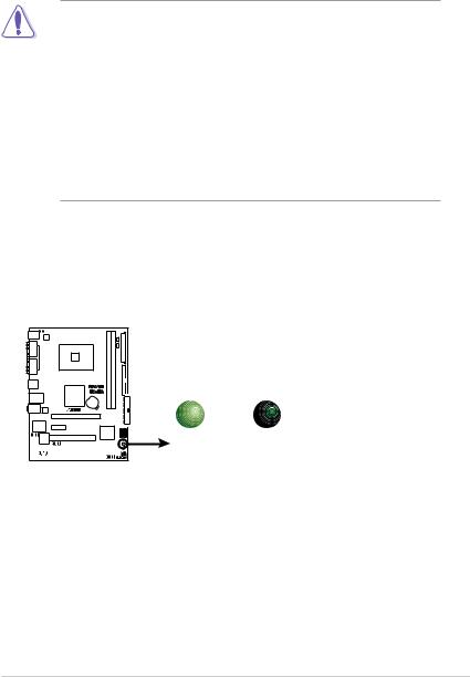
Onboard LED
The motherboard comes with a standby power LED that lights up to indicate that the system is ON, in sleep mode, or in soft-off mode. This is a reminder that you should shut down the system and unplug the power cable before removing or plugging in any motherboard component.
P5V-VM |
SB_PWR |
ULTRA |
|
ON OFF
|
|
|
|
|
|
|
|
|
|
|
|
|
|
|
|
Standby |
Powered |
|
|
|
|
|
|
|
|
|
|
|
|
|
|
|
|
Power |
Off |
P5V-VM ULTRA Onboard LED
ASUS P5V-VM Ultra Motherboard |
1- |

1.5 Motherboard Overview
1.5.1 Motherboard layout
|
|
18.3cm(7.2in) |
|
|
|
|
PS2_USB_PWR |
|
|
|
|
PS/2KBMS |
|
|
|
|
|
T: Mouse |
|
|
|
|
|
B: Keyboard |
|
|
|
|
|
COM1 |
ATX12V |
|
|
|
|
|
|
|
|
|
|
PARALLEL PORT |
|
LGA775 |
|
bit,240-pin module) |
it,240b -pin module) |
|
|
|
|
|
|
VGA1 |
|
|
|
DIMM1 (64 |
DIMM2 (64 |
USB12 |
|
|
P5V-VM |
||
|
|
DDR2 |
DDR2 |
||
|
|
|
|||
|
|
VIA |
ULTRA |
||
|
|
|
|
|
|
LAN_USB34 |
P4M890 |
|
|
|
|
|
CR2032 3V |
|
|
||
|
|
|
|
|
|
|
|
|
Lithium Cell |
|
|
Top:Line In |
|
|
CMOS Power |
|
|
|
|
|
|
|
|
Center:Line Out |
|
|
|
|
|
Below:Mic In |
REALTEK |
|
|
|
|
|
|
|
|
|
|
PCIEX16
SUPER I/O |
PCIEX1_1 |
|
|
|
|
|
|
VIA |
|
|
VT8237A |
AAFP |
4Mb |
PCI1 |
|
BIOS |
|
|
|
|
|
|
USB78 |
|
CD |
PCI2 |
|
|
|
ALC660 |
USB56 |
FLOPPY
EATXPWR
CHA_FAN CPU_FAN
PRI_IDE 24.4cm(9.6in)
|
|
|
|
|
|
|
|
|
|
|
|
|
|
|
|
SEC IDE |
|
|
|
|
|
|
|
|
||
|
|
|
|
|
|
|
||
|
|
|
|
|
|
|
||
|
|
|
|
|
|
|
||
|
|
|
|
|
|
|
|
|
SATA1 |
|
|
|
|
|
|
SATA2 |
|
|
|
|
|
|
|
|||
|
|
|
|
|
|
|
|
|
SB_PWR
SPEAKER |
PANEL_F |
CLRTC |
|
1- |
Chapter 1: Product Introduction |
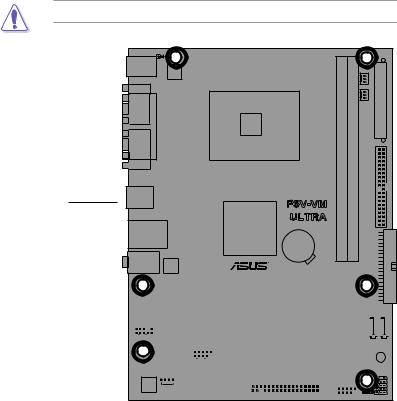
1.5.2 Placement direction
When installing the motherboard, make sure that you place it into the chassis in the correct orientation. The edge with external ports goes to the rear part of the chassis as indicated in the image below.
1.5.3 Screw holes
Place six (6) screws into the holes indicated by circles to secure the motherboard to the chassis.
Do not overtighten the screws! Doing so may damage the motherboard.
Place this side towards
the rear of the chassis
P5V-VM |
ULTRA |
|
|
|
|
|
|
|
|
|
|
|
|
|
|
|
|
|
|
|
|
|
|
|
|
|
|
|
|
|
|
|
|
|
|
|
|
|
|
|
|
|
|
|
|
|
|
|
|
|
|
|
|
|
|
|
|
|
|
|
|
|
|
|
|
|
|
|
|
|
|
|
|
|
|
|
|
|
|
|
|
|
|
|
|
|
|
|
|
|
|
|
|
|
|
|
|
|
|
|
|
|
|
|
|
|
|
|
|
|
|
|
|
|
|
|
|
|
|
|
|
|
|
|
|
|
|
|
|
|
|
|
|
|
|
|
|
|
|
|
|
|
|
|
|
|
|
|
|
|
|
|
|
|
|
|
|
|
|
|
|
|
|
|
|
|
|
|
|
|
|
|
|
|
|
|
|
|
|
|
|
|
|
|
|
|
|
|
|
|
|
|
|
|
|
|
|
|
|
|
|
|
|
|
|
|
|
|
|
|
|
|
|
|
|
|
|
|
|
|
|
|
|
|
|
|
|
|
|
|
|
|
|
|
|
|
|
|
|
|
|
|
|
|
|
|
|
|
|
|
|
|
|
|
|
|
|
|
|
|
|
|
|
|
|
|
|
|
|
|
|
|
|
|
|
|
|
|
|
|
|
|
|
|
|
|
|
|
|
|
|
|
|
|
|
|
|
|
|
|
|
|
|
|
|
|
|
|
|
|
|
|
|
|
|
|
|
|
|
|
|
|
|
|
|
|
|
|
|
|
|
|
|
|
|
|
|
|
|
|
|
|
|
|
|
|
|
|
|
|
|
|
|
|
|
|
|
|
|
|
|
|
|
|
|
|
|
|
|
|
|
|
|
|
|
|
|
|
|
|
|
|
|
|
|
|
|
|
|
|
|
|
|
|
|
|
|
|
|
|
|
ASUS P5V-VM Ultra Motherboard |
1- |
|
|||||||||||||||||

1.6 Central Processing Unit (CPU)
The motherboard comes with a surface mount LGA775 socket designed for the
Intel® Core™2 Extreme / Core™2 Duo / Pentium® D / Pentium® 4 / Celeron® D Processors.
•Your boxed Intel® Core™2 Extreme / Core™2 Duo / Pentium® D /
Pentium® 4 / Celeron® D Processors package should come with
installation instructions for the CPU, fan and heatsink assembly. If the instructions in this section do not match the CPU documentation, follow the latter.
•Upon purchase of the motherboard, make sure that the PnP cap is on the socket and the socket pins are not bent. Contact your retailer immediately if the PnP cap is missing, or if you see any damage to the PnP cap/socket pins/motherboard components.
ASUS will shoulder the cost of repair only if the damage is shipment/ transit-related.
•Keep the cap after installing the motherboard. ASUS will process Return Merchandise Authorization (RMA) requests only if the motherboard comes with the cap on the LGA775 socket.
•The product warranty does not cover damage to the socket pins resulting from incorrect CPU installation/removal, or misplacement/ loss/incorrect removal of the PnP cap.
1.6.1 Installling the CPU
To install a CPU:
1.Locate the CPU socket on the motherboard.
P5V-VM |
ULTRA |
P5V-VM ULTRA CPU Socket 775
Before installing the CPU, make sure that the socket box is facing towards you and the load lever is on your left.
1- |
Chapter 1: Product Introduction |

2.Press the load lever with your thumb (A) and move it to the left (B) until it is released from the retention tab.
Retention tab |
PnP Cap |
Load lever |
A |
|
|
|
B |
|
This side of the cam |
|
box should face you. |
To prevent damage to the socket pins, do not remove the PnP cap unless you are installing a CPU.
3.Lift the load lever in the direction of the arrow to a 135º angle.
4.Lift the load plate with your thumb and forefinger to a 100º angle (A), then push the PnP cap from the load plate window to remove (B).
B
A
Load
 plate
plate
5.Position the CPU over the socket, making sure that the gold triangle is on the bottom left corner of the socket. The socket
alignment key should fit into the CPU notch.
Alignment key
Gold triangle mark
ASUS P5V-VM Ultra Motherboard |
1- |

6. |
Close the load plate (A), then push |
A |
|
the load lever (B) until it snaps into |
|
|
the retention tab. |
|
B
The CPU fits in only one correct orientation. DO NOT force the CPU into the socket to prevent bending the connectors on the socket and damaging the CPU!
The motherboard supports Intel® LGA775 processors with the Intel® Enhanced Memory 64 Technology (EM64T), Enhanced Intel SpeedStep® Technology (EIST), and Hyper Threading Technology.
If you install a dual-core CPU, make sure to connect the chassis fan cable to CHA_FAN connector for system stability.
1-10 |
Chapter 1: Product Introduction |
1.6.2 Installling the CPU heatsink and fan
The Intel® Core™2 Extreme / Core™2 Duo / Pentium® D / Pentium® 4 / Celeron® D Processors require a specially designed heatsink and fan assembly to ensure optimum thermal condition and performance.
•Install the motherboard to the chassis before you install the CPU fan
and heatsink assembly
•When you buy a boxed Intel® Core™2 Extreme / Core™2 Duo / Pentium® D / Pentium® 4 / Celeron® D LGA775 processor, the packageincludes the CPU fan and heatsink assembly. If you buy a CPU separately, make sure that you use only Intel® certified multi directional heatsink and fan.
•Your I Intel® Core™2 Extreme / Core™2 Duo / Pentium® D / Pentium® 4 /
Celeron® D LGA775 heatsink and fan assembly comes in a push-pin design and requires no tool to install.
If you purchased a separate CPU heatsink and fan assembly, make sure that a Thermal Interface Material is properly applied to the CPU heatsink or CPU before you install the heatsink and fan assembly.
To install the CPU heatsink and fan:
1.Place the heatsink on top of the installed CPU, making sure that the four fasteners match the holes on the motherboard.
F
 astener
Motherboard 


Make sure each fastener is oriented as shown, with the narrow groove directed outward.
ASUS P5V-VM Ultra Motherboard |
1-11 |

2. Push down two fasteners at a time |
|
|
|||
|
|
||||
in a diagonal sequence to secure |
|
B |
|||
the heatsink and fan assembly in |
|
||||
|
|
||||
place. |
|
|
A |
A |
|
|
|
|
|
|
|
|
|
|
|
|
|
|
A |
B |
|
B |
|
BA
3.When the fan and heatsink assembly is in place, connect the CPU fan cable to the connector on the motherboard labeled CPU_FAN.
P5V-VM |
ULTRA |
CPU_FAN
Rotation
+12V
 GND
GND
P5V-VM ULTRA CPU Fan Connector
Do not forget to connect the CPU fan connector! Hardware monitoring errors can occur if you fail to plug this connector.
1-12 |
Chapter 1: Product Introduction |
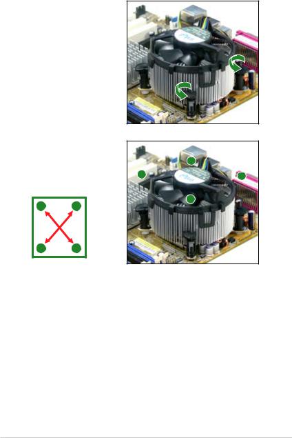
1.6.3 Uninstalling the CPU heatsink and fan
To uninstall the CPU heatsink and fan:
1.Disconnect the CPU fan cable from the connector on the motherboard.
2.Rotate each fastener counterclockwise.
3.Pull up two fasteners at a time in a diagonal sequence to disengage the heatsink and fan assembly from the motherboard.
A |
B |
|
|
|
|
B |
|
A |
|
A |
|
B |
|
B
A
ASUS P5V-VM Ultra Motherboard |
1-13 |

4.Remove the heatsink and fan assembly from the motherboard.
5.Rotate each fastener clockwise to reset the orientation.
The narrow end of the groove should point outward after resetting. (The photo shows the groove shaded for emphasis.)
Narrow end of the groove
1-14 |
Chapter 1: Product Introduction |
 Loading...