


Softstarters
—
1SFC132057M0201
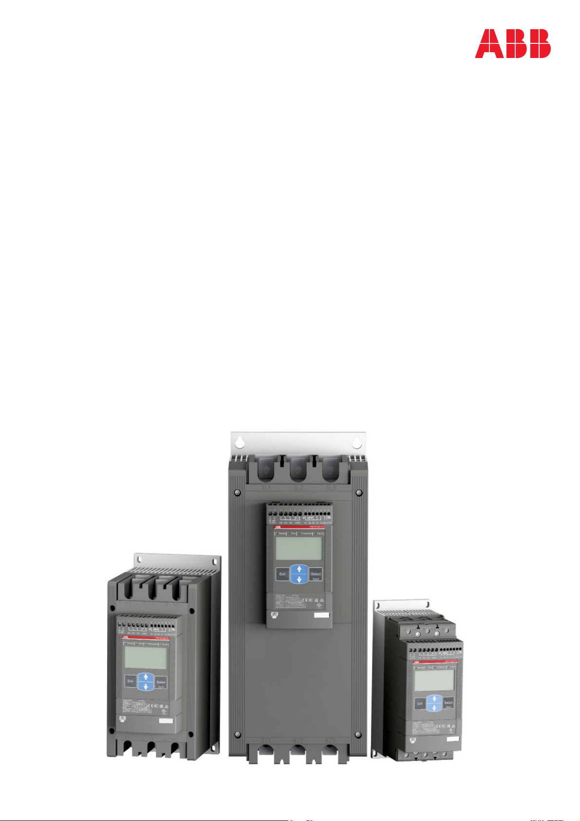
Softstarters Type PSE18...PSE370
Installation and commissioning manual

This manual belongs to:
__________________________________________
Softstarters Type PSE18...PSE370 Installation and commissioning manual 1SFC132057M0201
2

Installation and Commissioning Manual
ABB Softstarters PSE18...PSE370
1 General
This is the Installation and Commissioning Manual for Softstarters Type
PSE18…PSE370.
Document number: 1SFC132057M0201
Revision: G
Issue date: 2018-11-20
Data subject to change without notice.
We reserve all rights to this document, even in the event that a patent is issued
and a different commercial proprietary right is registered. Improper use, in particular reproduction and dissemination to third parties, is not permitted.
This document has been carefully checked. If the user nevertheless detects any
errors, he is kindly asked to notify us as soon as possible.
The data contained in this manual is intended solely for the product description and is not to be deemed to be a statement of guaranteed properties. In the
interests of our customers, we constantly seek to ensure that our products are
developed to the latest technological standards.
As a result, there may be some differences between the softstarter and the information in this manual.
Author’s address:
ABB AB
Control Products
SE-721 61 Västerås, Sweden
Telephone: +46 (0) 21 32 07 00
www.new.abb.com/lowvoltage/products/softstarters
www.abb.com/drives
© Copyright 2018. All rights reserved. Specifi cation subject to changes without notice.
Softstarters Type PSE18...PSE370 Installation and commissioning manual 1SFC132057M0201 3

2 Safety
This chapter describes warning and information signs used in this manual, which
the user should pay attention to.
The softstarter shall be installed by authorized personnel only.
This manual is a part of the PSE Softstarter and should always be accessible to
personnel working with this product.
The manual shall always be read through before performing any installation or
commissioning tasks.
2.1 Use of signs warning and information
Warning!
Warning symbol indicates the presence of hazardous voltage which
could result in personal injury.
Warning!
General warning symbol indicates the presence of a hazard which could
result in personal injury and damage to equipment or property.
Information
Information sign alerts the reader to pertinent facts and conditions.
Softstarters Type PSE18...PSE370 Installation and commissioning manual 1SFC132057M0201
4

Chapter
1 Introduction ............................................ 7
2 Quickstart ............................................... 11
3 Description ............................................. 15
4 Mounting ................................................ 27
5 Connection ............................................. 31
6 Human-Machine Interface (HMI) .............. 45
7 Functions and confi guration .................... 55
8 Fieldbus communication ......................... 79
9 Maintenance ........................................... 81
10 Troubleshooting ...................................... 83
11 Wiring diagrams ...................................... 95
12 Index ...................................................... 99
Customer feedback report ............................... 102
Softstarters Type PSE18...PSE370 Installation and commissioning manual 1SFC132057M0201 5

Notes
Softstarters Type PSE18...PSE370 Installation and commissioning manual 1SFC132057M0201
6

Chapter 1 Introduction
Documentation for PSE18...PSE370 softstarter .......................................... 8
Installation and Commissioning Manual ...................................................... 8
Intended audience ................................................................................. 9
General ............................................................................................. 9
Requirements .................................................................................... 9
Revision notes and other documents ..................................................... 9
Acronyms and abbreviations .................................................................. 9
Explanation of concepts ......................................................................... 10
Cyber Security Legal Disclaimer .................................................................. 10
Softstarters Type PSE18...PSE370 Installation and commissioning manual 1SFC132057M0201 7 Chapter 1

Chapter 1 Introduction
1.1 Documentation for PSE18...PSE370 softstarter
For the Softstarter Type PSE18...PSE370, the following manuals are available:
1SFC132059M9901 (User manual short form, printed)
1SFC132057M0201 (English version, PDF-fi le)
1.2 Installation and Commissioning Manual
This manual contains instructions on how to install, commission and maintain the
softstarter. The manual covers procedures for mechanical and electrical installation, and installation of communication devices. It also covers energizing, setting,
and confi guration and verifying settings.
For brief information see Softstarters Type PSE18...PSE370 User Manual short
form, containing the same languages as the Installation and Commissioning
Manual. Softstarters Type PSE18...PSE370 User Manual short form has document ID 1SFC132059M9901.
For quickest possible start, read Chapter 2 Quickstart or go to the short form
manual (1SFC132059M9901).
A complete compilation of ABB’s softstarters can be found in Main catalogue
Softstarters, document ID 1SFC132012C0201.
Softstarters Type PSE18...PSE370 Installation and commissioning manual 1SFC132057M02018 Chapter 1

1.2.1 Intended audience
1.2.1.1 General
The installation and commissioning manual is intended for the installation, commissioning, and maintenance personnel responsible for getting the softstarter into
normal service and out of service.
1.2.1.2 Requirements
The installation personnel must have a basic knowledge in handling electric equipment. The commissioning and maintenance personnel must be well experienced
in using this kind of equipment.
1.2.2 Revision notes and other documents
For latest information on revisions and other documents related to the PSE Softstarters, please check
www.new.abb.com/low-voltage/products/softstarters
www.abb.com/drives
1.2.3 Acronyms and abbreviations
The acronyms and abbreviations described in table 1.1 are used in this manual.
Table 1.1
Acronym/ abbreviation
BP By-pass
DOL Direct-on-line
EOL Electronic overload protection for the Motor
FB Fieldbus
FBP FieldBusPlug
HMI Human-Machine Interface
I
e
IT Information Technology
LCD Liquid Crystal Display
LED Light Emitting Diode
PCB Printed Circuit Board
PLC Programmable Logic Controller
PTC Positive Temperature Coeffi cient
RTU Remote Terminal Unit
SC Short Circuit
SCR Silicon Controlled Rectifi er ( thyristor)
TOR Top of Ramp ( full voltage/ Full-On)
U
c
U
e
U
s
Description
Rated operational current
Rated control circuit voltage *
Rated operational voltage *
Rated control supply voltage *
*) For defi nition see IEC 60947-1 edition 5.0
Softstarters Type PSE18...PSE370 Installation and commissioning manual 1SFC132057M0201 9 Chapter 1

1.2.4 Explanation of concepts
The setting of current Ie is the setting for the rated operational current (main current) of the motor.
Ue = Rated operational voltage on the motor’s operational current (three phase
main voltage feeding the motor).
Us = Rated control supply voltage, feeding the electronics in the softstarter.
Uc = Rated control voltage, used for controlling the softstarter.
1.3 Cyber Security Legal Disclaimer
This product is designed to be connected to and to communicate information and
data via a communication interface. It is Customer’s sole responsibility to provide
and continuously ensure a secure connection between the product and Customer
network or any other network (as the case may be). Customer shall establish and
maintain any appropriate measures (such as but not limited to the installation of
fi rewalls, application of authentication measures, encryption of data, installation of
anti-virus programs, etc) to protect the product, the network, its system and the
interface against any kind of security breaches, unauthorized access, interference,
intrusion, leakage and/or theft of data or information.
ABB Ltd and its affi liates are not liable for damages and/or losses related to such
security breaches, any unauthorized access, interference, intrusion, leakage and/
or theft of data or information.
Softstarters Type PSE18...PSE370 Installation and commissioning manual 1SFC132057M020110 Chapter 1

Chapter 2 Quickstart
Quickstart ................................................................................................... 12
Softstarters Type PSE18...PSE370 Installation and commissioning manual 1SFC132057M0201 11 Chapter 2
Ready Run
A
Protection
B
Fault
Chapter 2 Quickstart
This chapter is a short guide on how to connect, confi gure and start the
softstarter in the easiest way.
This product has been carefully manufactured and tested but there is a
risk that damage can occur from abnormal handling during transportation.
Therefore, the procedure below should be followed during initial installation:
Warning!
Mounting, electrical connection and settings of the softstarter shall
be made in accordance with existing laws and regulations and be
performed by authorized personnel.
Exit
Select
Reset
C DE
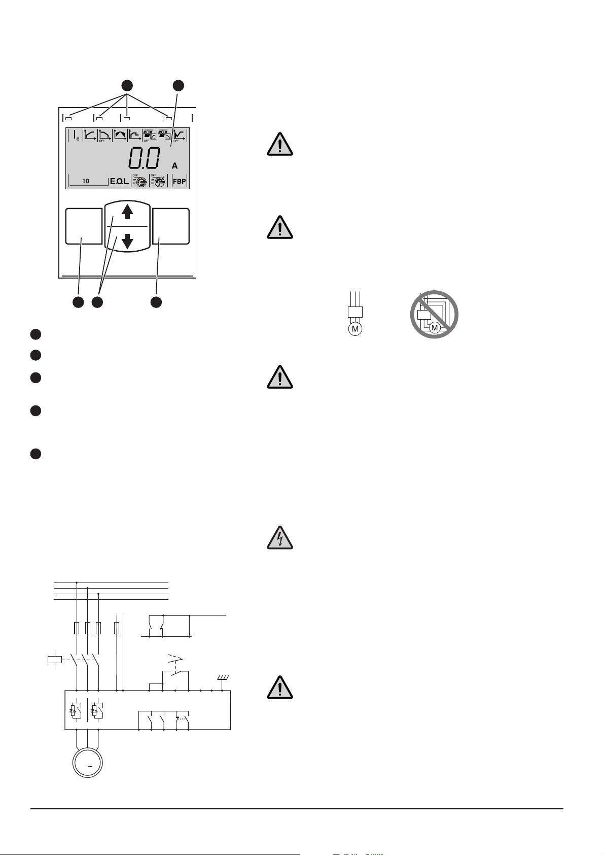
Figure 2.1:
LED status indicators.
A
B
LCD display with backlight.
Exit key for cancelling parameter edits and
C
moving up one menu level.
Select/Reset key for changing and storing
D
parameter values, moving down one menu
level, and to reset tripping events.
E
Navigation keys for navigating the menu and
changing parameter values. Flashing numbers
or text shown in the display indicates that the
menu/value can be changed or scrolled.
1SFC132235F0001
Warning!
Connecting Softstarters PSE18...PSE370 Inside Delta will cause damage to the equipment, and there is a risk of death or serious injury.
PSE
1SFC132265F0001
In Line Inside Delta
PSE
1SFC132263F0001
Warning!
Before connecting the PSE18...PSE170 to operational voltage(Ue) for
the fi rst time, the supply voltage(Us) must be connected and turned
on to ensure the bypass relay is switched to open position. This is
necessary to avoid unintentional starting of the equipment during the
connection.
1. Be aware of the ambient temperature. Derating is required above 40 °C
(104 °F). See chapter 3.6.
2. Mount the softstarter according to Chapter 4 Mounting.
L1
L2
L3
N
LN
Start Stop
KM1
1L1 3L2 5L3
2T1 4T2 6T3
U
V
12 1489
W
89
Start
Stop
Run
TOR Fault
NC NO
67
543
11
11
1210 13
M
3
Figure 2.2: Example connection of PSE Softstarter
Softstarters Type PSE18...PSE370 Installation and commissioning manual 1SFC132057M020112 Chapter 2
Warning!
Hazardous voltage. Will cause death or serious injury. Turn off and
lock out all power supplying this device before starting work on this
equipment.
3. Connect the terminals 1 L1, 3 L2 and 5 L3 to the operational voltage on the
power supply line side.
4. Connect the terminals 2T1, 4T2 and 6T3 to the motor.
Warning!
Capacitors for power factor compensation are not allowed between
the softstarter and the motor, since this can cause current peaks
which can damage the thyristors in the softstarter. If such capacitors are to be used, they should be connected on the line side of the
softstarter.
1SFC132237F0001
5. Connect control supply voltage to terminals 1 and 2 (100-250 V 50/60 Hz).
Exit
Select
Reset
B
Exit
Exit
Select
Reset
C
Select
Reset
D
6. Connect the functional earth to terminal 14, with an earthing point close to
the softstarter.
The earthing is not a protective earth, it is a functional earth. The earthing
cable should be as short as possible. Maximum length 0.5 m. The earthing
cable should be connected to the mounting plate, which should also be
earthed.
7. Connect the start, stop and other control circuits including the analog out to
the terminals, 8, 9, 10, 11, 12, 13 if needed. This section is using an internal
24 V DC. Do not feed with any external voltage.
Select
Reset
A
Exit
Select
Reset
Warning!
Do not connect an external voltage to the control terminals 8, 9, 10,
11, 12, 13 and 14. Failure to observe the above may damage the softstarter and the warranty may no longer be valid.
8. Connect terminals 3, 4, 5, 6 and 7 when using the signal output relays. These
are potential free contacts for maximum 250 V AC, 1,5 A AC-15. Make sure
you are using the same voltage level within this terminal section.
1SFC132268F0001
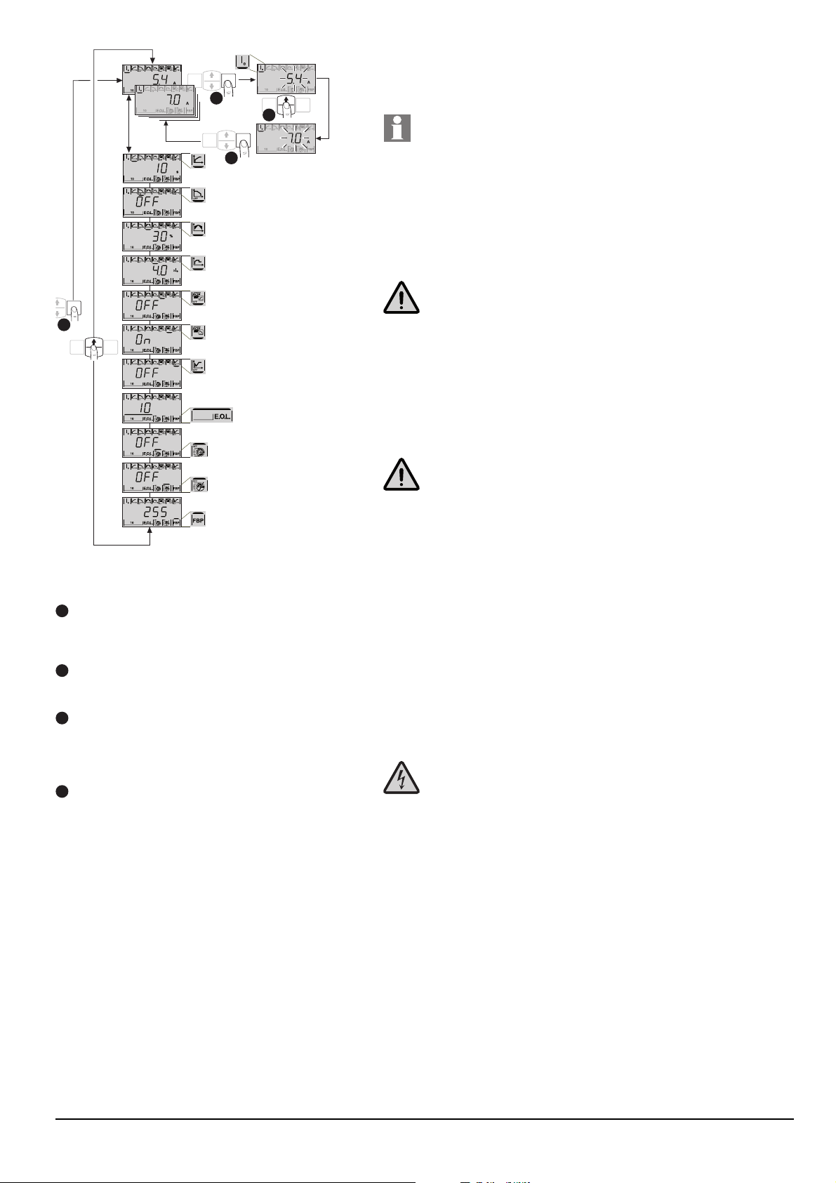
Figure 2.3:
Confi guration of the parameter Rated Current.
A
If disabled, press any key to activate the light
in the display. Enter the application setting by
pressing the Select key a second time.
B
Press select again to enable editing of the Ie
parameter. This is indicated by a fl ashing value.
Increase or decrease the value by pressing the
C
Up or Down keys repeatedly. Holding the key
down will speed up the change. Press the Exit
key to abort change.
D
When the rated current of the motor is
reached, press the Select key again to save.
If needed, continue to set other parameters
according to the application following the
same procedure.
Press the Exit key to return to the top level.
Warning!
The same external voltage (maximum 24 V DC or maximum 250 V
AC) must be connected to the output relay terminals 3, 4, 5, 6 and 7.
Failure to observe the above may damage the softstarter and the warranty may no longer be valid.
9. Switch ON the control supply voltage Us, terminals 1 and 2.
10. Continue to confi gure parameter Ie as described in fi gure 2.3. Complete
information about confi guration is available in Chapter 6 Human-Machine
Interface (HMI) and Chapter 7 Functions and confi guration.
11. Switch ON the operational voltage Ue. The green “Ready” LED will turn solid.
12. Give start command to the softstarter.
Warning!
Depending on the two phase control, a connected motor terminal
always carries live hazardous voltage. Do not touch terminals when
voltage is applied. Output terminals will have live voltage even when
the device is OFF. This can cause death or serious injury.
Softstarters Type PSE18...PSE370 Installation and commissioning manual 1SFC132057M0201 13 Chapter 2

This page is intentionally left blank.
Softstarters Type PSE18...PSE370 Installation and commissioning manual 1SFC132057M020114 Chapter 2

Chapter 3 Description
Overview .................................................................................................... 16
Markings and connections .......................................................................... 17
Type designation ......................................................................................... 18
Documentation ........................................................................................... 18
Environmental infl uence .............................................................................. 18
Specifi cations ............................................................................................. 18
Technical data ............................................................................................ 19
General .................................................................................................. 19
Weights .................................................................................................. 19
PSE Softstarter types ............................................................................. 20
IEC information ...................................................................................... 21
information .............................................................................. 21
Dimensions ............................................................................................ 22
Drilling plan ............................................................................................ 24
Softstarters Type PSE18...PSE370 Installation and commissioning manual 1SFC132057M0201 15 Chapter 3
Chapter 3 Description
This chapter describes the PSE Softstarter in general, specifi cations as well as
available accessories and spare parts.
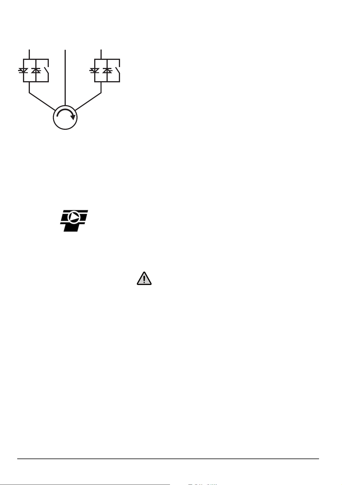
L1
L2 L3
M
Figure 3.1: Integrated By-pass. Controlled
phases 1 and 3 (L1 and L3).
3.1 Overview
The PSE Softstarter is a microprocessor-based softstarter designed with the latest
technology for soft starting and soft stopping of three-phase squirrel cage motors.
The softstarter has several advanced features as standard.
• Integrated by-pass in phases L1 and L3, see fi gure 3.1.
• Thyristors are used on phases L1 and L3 for controlling the motor voltage.
1SFC132253F0001
• Select between voltage ramp or torque control during start and stop.
• Motor protection, as well as underload and locked rotor protection.
The keypad on the front is designed to be as user-friendly as possible, with a clear
display showing icons.
The PSE Softstarter can be controlled in two ways:
• Hardwire inputs control
• Fieldbus communication interface
Only one type of control method can be enabled simultaneously. Default selection
is hardwire inputs control.
The integrated fans for cooling are operated only during ramping ( start/stop) and
when the temperature of the heat sink is high. The temperature is monitored by a
thermistor mounted on the heat sink.
Phase L2 is directly connected to the motor, see fi gure 3.1.
Figure 3.2: Torque control is offered as standard
with the PSE softstarter.
Check that you have the correct product in regards to operational voltage, control
supply voltage and rated motor data. See chapter 3.3 Type designation.
The PSE18...PSE370 Softstarters operates over wide voltage ranges.
• Rated operational voltage 208 - 600 V AC
• Rated control supply voltage 100 - 250 V AC
Warning!
The product should only be used within the specifi ed ratings.
Be aware of the ambient temperature and altitude above sea level. Derating
is required above 40 °C (104 °F) and above 1000 m (3281 ft).
Softstarters Type PSE18...PSE370 Installation and commissioning manual 1SFC132057M020116 Chapter 3
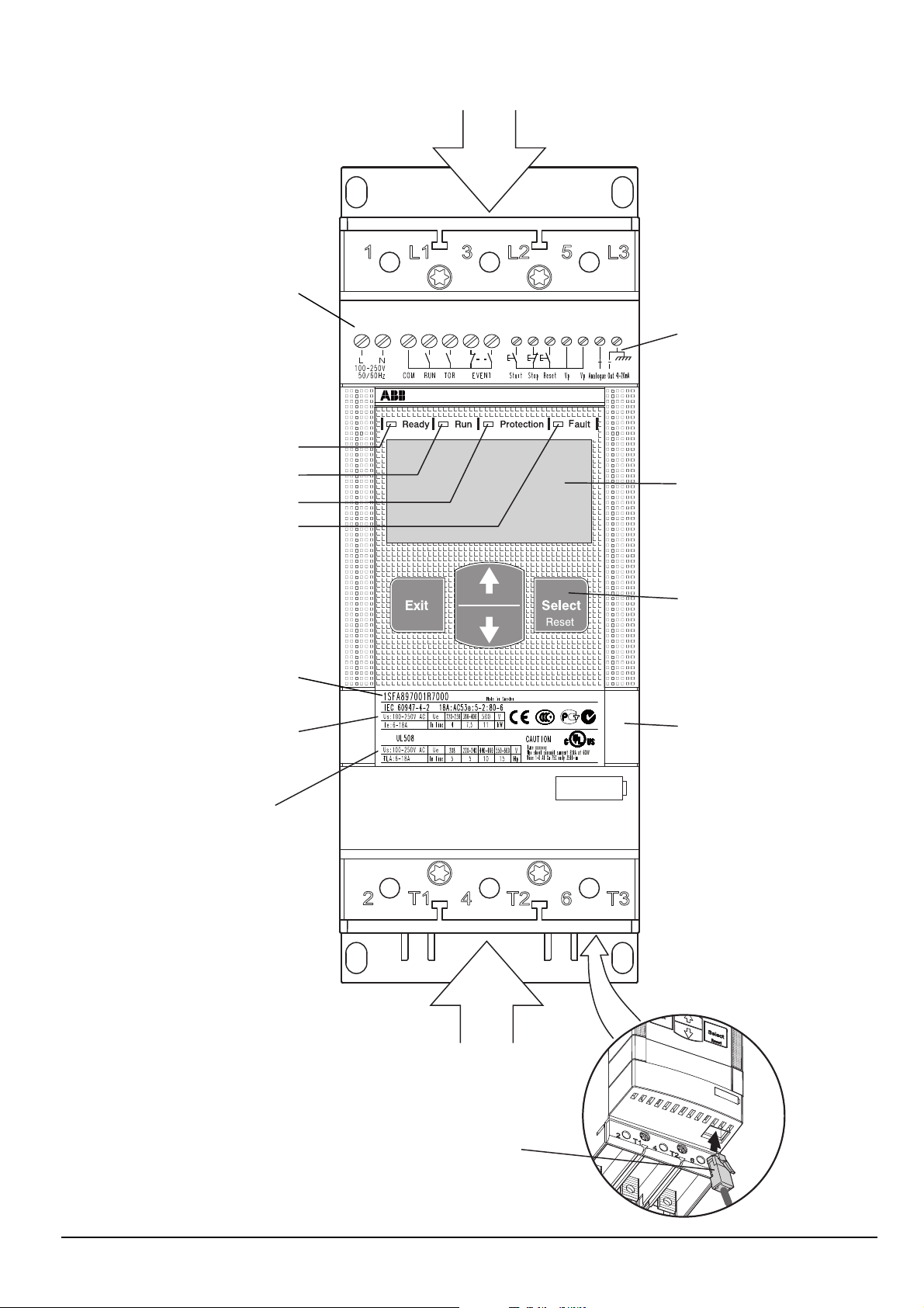
3.2 Markings and connections
Line side connection
Supply voltage U
Green
Green
Yellow
Red
Order code
Technical data according
to IEC 947-4-2
s
81 2 3 4 5 6 7 9 10 11 12 13 14
Terminal marking of
control circuits
PSE 18-600-70
Display
Keypad
Fieldbus connection
Technical data
according to UL 508
and CSA-C22.2 No. 14-05
Figure 3.3: Markings and connections
1SFC132238F0001
Motor side connection
External Keypad connection
Softstarters Type PSE18...PSE370 Installation and commissioning manual 1SFC132057M0201 17 Chapter 3
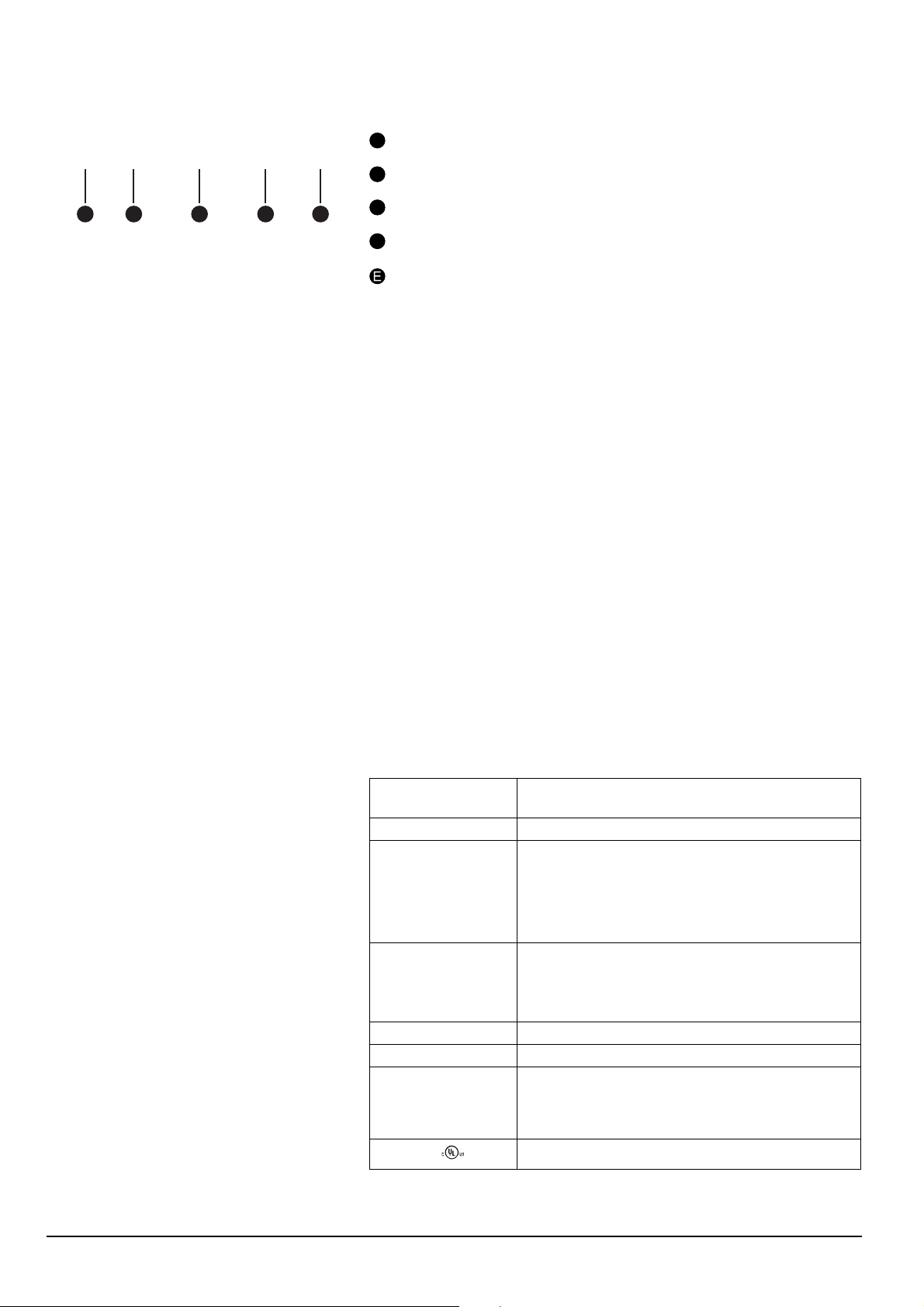
PSE18 - 600 - 70 - 1
A
B
C
D E
3.3 Type designation
Type designation to be found on the softstarters front. See fi gure 3.4.
A
Softstarter type: PSE
B
Current rating: 18 = 18 A
C
Operational voltage: 600 = 208 - 600 V 50/60 Hz
Control supply voltage: 70 = 100 - 250 V 50/60 Hz
D
Figure 3.4: Type designation
Design code (PSE210...PSE370 only)
3.4 Documentation
Documentation such as brochures, catalogs, certifi cates, and drawings included
can be found at:
www.new.abb.com/lowvoltage/products/softstarters.
3.5 Environmental infl uence
The product is designed to minimize the environmental effects during manufacturing and use of the product. Most of the materials used, are of recycle type, and
shall be handled and recycled according to existing laws.
Further information regarding used material and recycling of the product can be
found at:
www.new.abb.com/low-voltage/products/softstarters
www.abb.com/drives
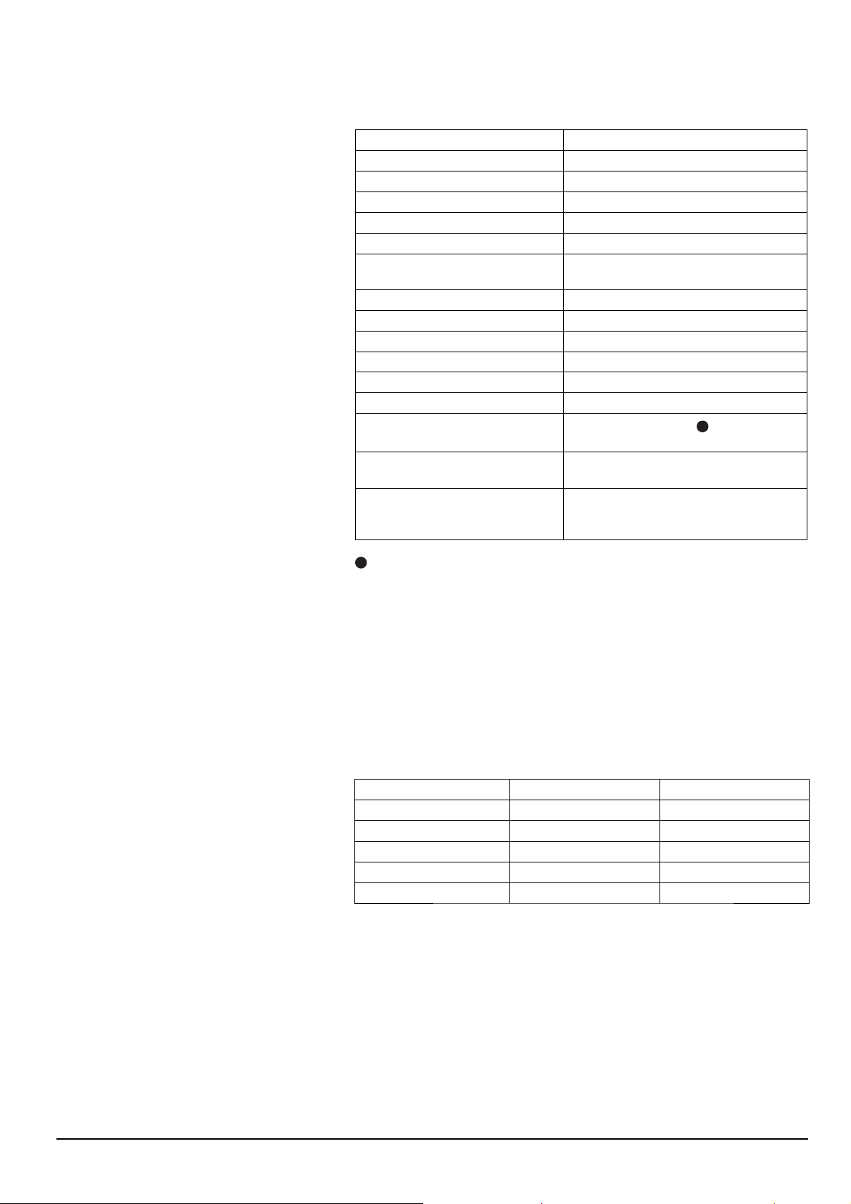
3.6 Specifi cations
Table 3.1
Degree of protection
( Operational circuit)
Operating position Vertical at ±
Ambient temperature Storage. -40 oC to + 70 oC (-40 oF to 158 oF)
Altitude 1000 m (3281 ft.) above sea level without derating.
Pollution degree 3
Relative humidity 5-95% (non-condensing)
Standards IEC 60947-1
Standards
IP 00
o
30
o
Operation: -25
derating.
o
C to + 60 oC (104 oF to 140 oF) with derating 0.6
+ 40
o
C (0.6% / 1,8 oF).
% /1
1000-4000 m (3281 - 13123 ft.) above sea level with
derating
0.67 % per 100 m above 1000 m
IEC 60947-4-2
EN 60947-1
EN 60947-4-2
UL 508, CSA C22.2 No 14-10
C to + 40 oC (-13 oF to 104 oF) without
Softstarters Type PSE18...PSE370 Installation and commissioning manual 1SFC132057M020118 Chapter 3
3.7 Technical data
3.7.1 General
Table 3.2
General data
Rated insulation voltage, U
Rated operational voltage, U
Rated control supply voltage, U
Voltage tolerance +10% to -15%
Frequency tolerance
Rated impulse withstand voltage 6 kV operational circuit
Number of controlled phases 2
Inputs Start, stop, reset
Analog out 4-20 mA
Cooling system Fan
Rated form Form 1
Rated duty Uninterrupted
EMC
Recommended fuse
Supply circuit
Communication protocols, Internal
Modbus RTU
i
e
600 V
208-600 V 50 / 60 Hz
100 - 250 V 50 / 60 Hz
s
±
5%
/ 4 kV control supply circuit
IEC 60947-4-2 Class A
Lloyd’s Register (2002)
6A Delayed
MCB use characteristics
DeviceNet with fi eldbus plug/Profi bus
DP with fi eldbus plug/ Modbus RTU with
fi eldbus plug
1
1
This product has been designed for environment A. Use of this product in environmentB
may cause unwanted electromagnetic disturbances in which case the user may be
required to take adequate mitigation measures.
3.7.2 Weights
Table 3.3
Type Weight in kg Weight in lbs
PSE18...PSE60 2.4 5.3
PSE72...PSE105 2.5 5.5
PSE142...PSE170 4.2 9.2
PSE210 9.5 20.9
PSE250...PSE370 10.9 24.0
Softstarters Type PSE18...PSE370 Installation and commissioning manual 1SFC132057M0201 19 Chapter 3

3.7.3 PSE Softstarter types
Table 3.4
t ≤ + 40 oC (104 oF)
IEC
220-
240 V
Softstarter
type
PSE18 18 4 7.5 11 18 5 5 10 15
PSE25 25 5.5 11 15 25 7.5 7.5 15 20
PSE30 30 7.5 15 18.5 28 7.5 10 20 25
PSE37 37 9 18.5 22 34 10 10 25 30
PSE45 45 11 22 30 42 10 15 30 40
Ie (A)
P (kW)
380400 V
P (kW)
500 V
P (kW) FLA (A)
208 V
P (HP)
220240 V
P (HP)
440480 V
P (HP)
550600 V
P (HP)
PSE60 60 15 30 37 60 20 20 40 50
PSE72 72 18.5 37 45 68 20 25 50 60
PSE85 85 22 45 55 80 25 30 60 75
PSE105 106 30 55 75 104 30 40 75 100
PSE142 143 40 75 90 130 40 50 100 125
PSE170 171 45 90 110 169 60 60 125 150
PSE210 210 59 110 132 192 60 75 150 200
PSE250 250 75 132 180 248 75 100 200 250
PSE300 300 90 160 200 302 100 100 250 300
PSE370 370 110 200 250 361 125 150 300 350
Softstarters Type PSE18...PSE370 Installation and commissioning manual 1SFC132057M020120 Chapter 3

3.7.4 IEC information
For more information see: https://applications.it.abb.com/SOC/Motor
3.7.5 information
For more information see: https://applications.it.abb.com/SOC/Motor
Softstarters Type PSE18...PSE370 Installation and commissioning manual 1SFC132057M0201 21 Chapter 3
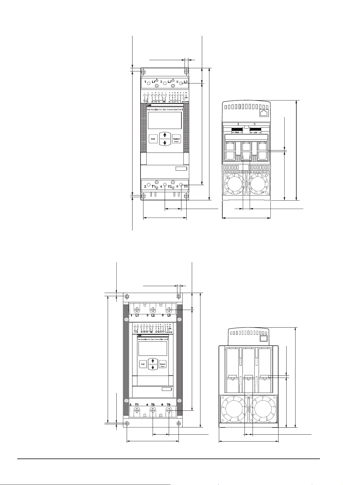
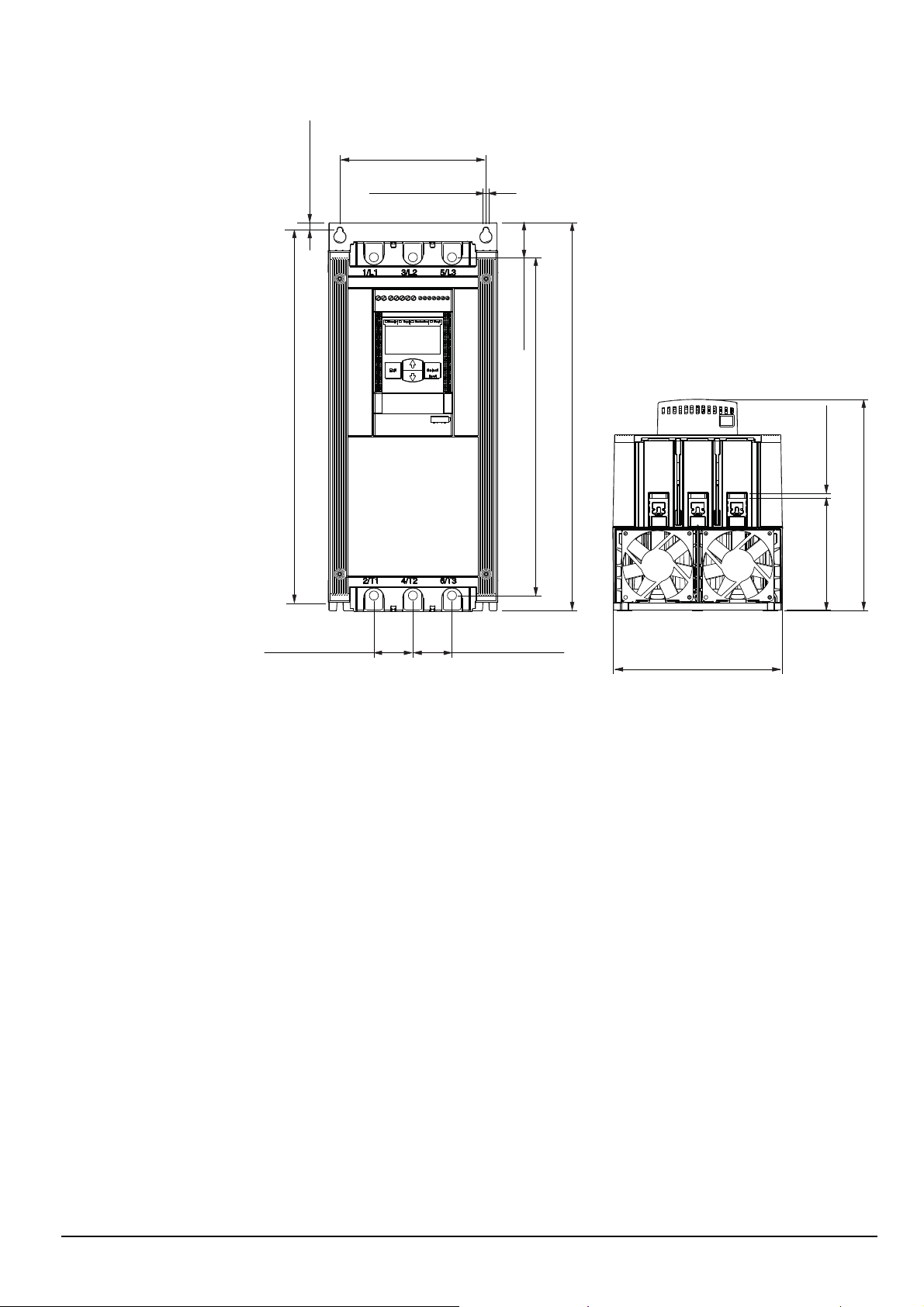
3.7.6 Dimensions
Dimensions PSE18...PSE105
6 mm (0.24 in)
6,5 mm (0.26 in)
230 mm (9.06 in)
80 mm (3.14 in)
PSE 18-600-70
245 mm (9.65 in)
188 mm (7.40 in) 28 mm (1.12 in)
30 mm (1.18 in)
185,5 mm (7.30 in)
90 mm (3.54 in) 3 mm (0.12 in)
13 mm (0.51 in)
90 mm (3.54 in)
3 mm (0.12 in)
7 mm (0.28 in)
278 mm (10.94 in)
Dimensions PSE142...PSE170
6,5 mm (0.26 in)
37 mm (1.46 in)
PSE142-600-70
221 mm (8.70 in)
295 mm (11.61 in)
5 mm (0.20 in)
219,5 mm (8.64 in)
3 mm (0.12 in)
35 mm (1.38 in)
113,5 mm (4.47 in)
Softstarters Type PSE18...PSE370 Installation and commissioning manual 1SFC132057M020122 Chapter 3
130 mm (5.12 in)
109,5 mm (4.31 in)
1SFC132260F0001
17,5 mm (0.69 in)
163.5 mm (6.44 in)
6.5 mm (0.26 in)
8.2 mm (0.32 in)
Dimensions PSE210...PSE370
39 mm (1.54 in)
418 mm (16.46 in)
43.75 mm (1.72 in)
379 mm (14.92 in)
43.75 mm (1.72 in)
435 mm (17.13 in)
236.5 mm (9.31 in)
125.5 mm (4.94 in) 5 mm (0.20 in)
190 mm (7.48 in)
Softstarters Type PSE18...PSE370 Installation and commissioning manual 1SFC132057M0201 23 Chapter 3
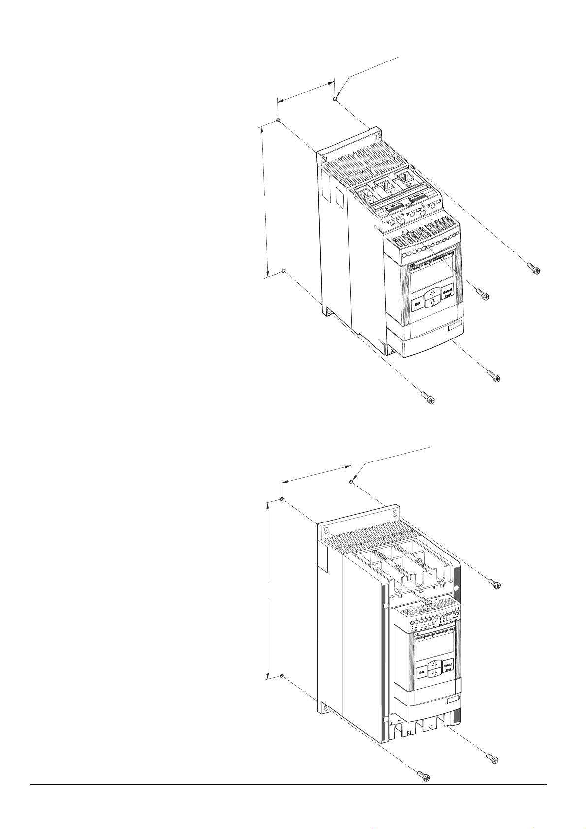
3.7.7 Drilling plan
Drilling plan PSE18...PSE105
80 mm
(3.14 in)
230 mm (9.06 in)
M6 (1/4 in)
1SFC132271F0001
Drilling plan PSE142...PSE170
113,5 mm
(4.47 in)
278 mm (10.94 in)
M6 (1/4 in)
70
0-
60
2-
14
SE
P
1SFC132272F0001
Softstarters Type PSE18...PSE370 Installation and commissioning manual 1SFC132057M020124 Chapter 3
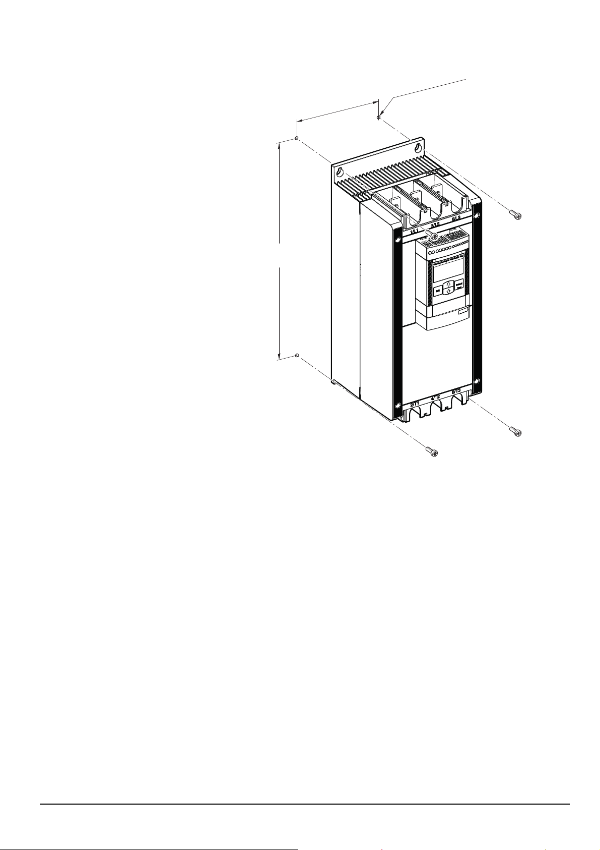
Drilling plan PSE210...PSE370
418 mm (16.46 in)
163,5 mm
M6 (1/4 in)
(6.44 in)
1SFC132273F0001
Softstarters Type PSE18...PSE370 Installation and commissioning manual 1SFC132057M0201 25 Chapter 3

This page is intentionally left blank.
Softstarters Type PSE18...PSE370 Installation and commissioning manual 1SFC132057M020126 Chapter 3

Chapter 4 Mounting
Receiving, unpacking and checking ............................................................ 28
Intermediate storage .............................................................................. 28
Mounting .................................................................................................... 28
Handling when mounting ....................................................................... 28
Requirements ......................................................................................... 29
Minimum enclosure size ......................................................................... 29
Minimum distance to wall and front ........................................................ 30
Softstarters Type PSE18...PSE370 Installation and commissioning manual 1SFC132057M0201 27 Chapter 4
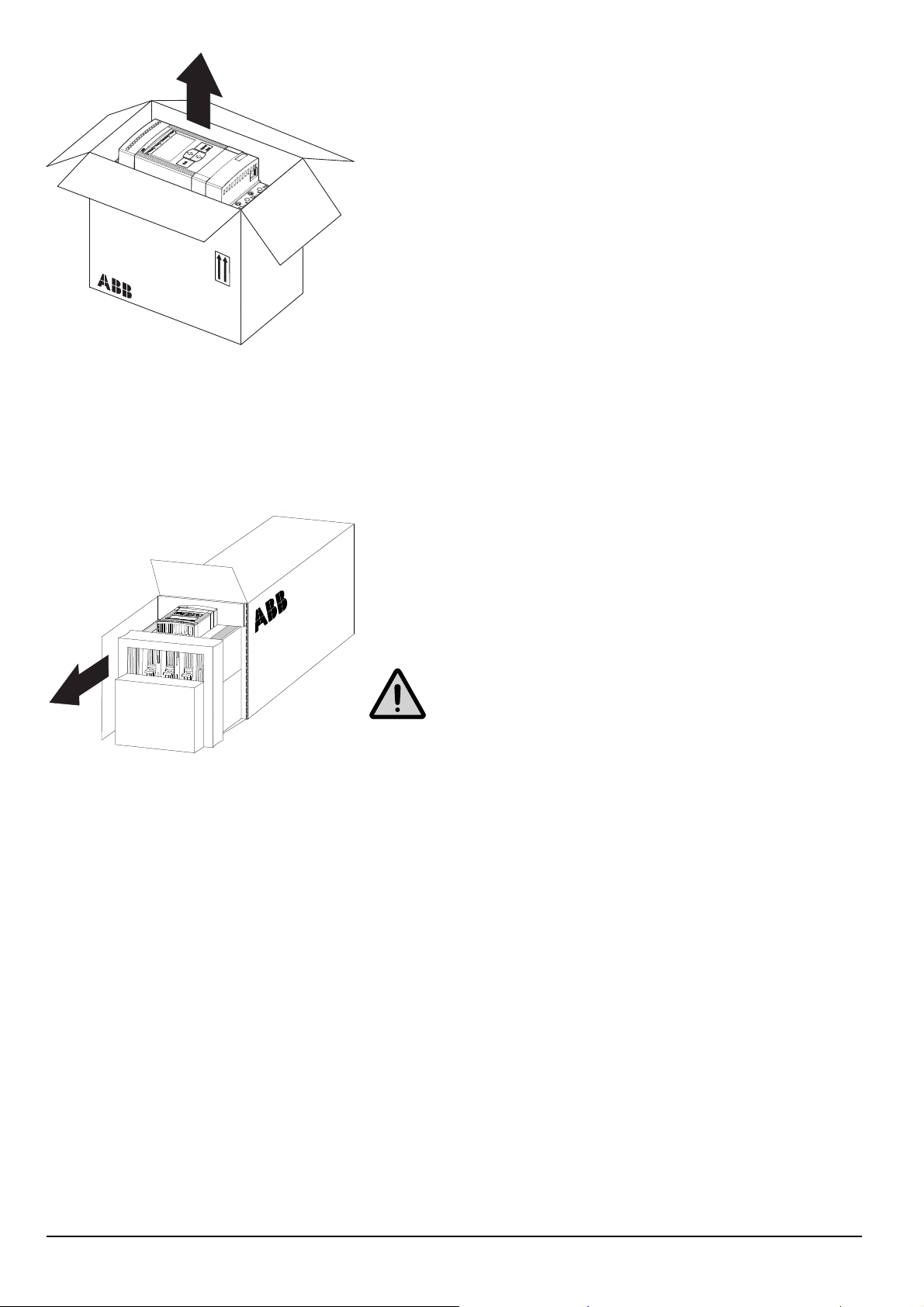
Figure 4.1: Unpacking PSE18...PSE170
Chapter 4 Mounting
This chapter describes instructions on how to receive the softstarter and how to
mount it in a proper way.
4.1 Receiving, unpacking and checking
• Check that the package is turned with the correct side up, fi gures 4.1 and
• Check for transport damages.
• Remove the transport casing.
• Visually inspect the softstarter.
• Check that the order code corresponds with the delivery documents.
1SFC132239F0001
• Check that all items are included, according to the delivery note.
• Check the softstarter as well as the package. If you fi nd any damages, please
4.1.1 Intermediate storage
Until the softstarter is mounted it should be stored in its package.
4.2.
contact the transport company or the supplier immediately.
Figure 4.2: Unpacking PSE210...PSE370
4.2 Mounting
4.2.1 Handling when mounting
The softstarter is available in three physical sizes. All models of PSE can be taken
out of the packages and be mounted without lifting equipment. See chapter 3.7.2
for weights.
Warning!
Never lift the softstarter by the connection bars, since it may cause damage
to the product.
Softstarters Type PSE18...PSE370 Installation and commissioning manual 1SFC132057M020128 Chapter 4
H
4.2.2 Requirements
See Chapter 3 Description for environmental requirements.
The PSE Softstarters exist in three different physical sizes which are designed to
be mounted with M6 (1/4 in.) bolts as well as bolts of equivalent dimension and
strength. Measures and drilling plans will be found in chapters 3.7.6 Dimensions
and 3.7.7 Drilling plan.
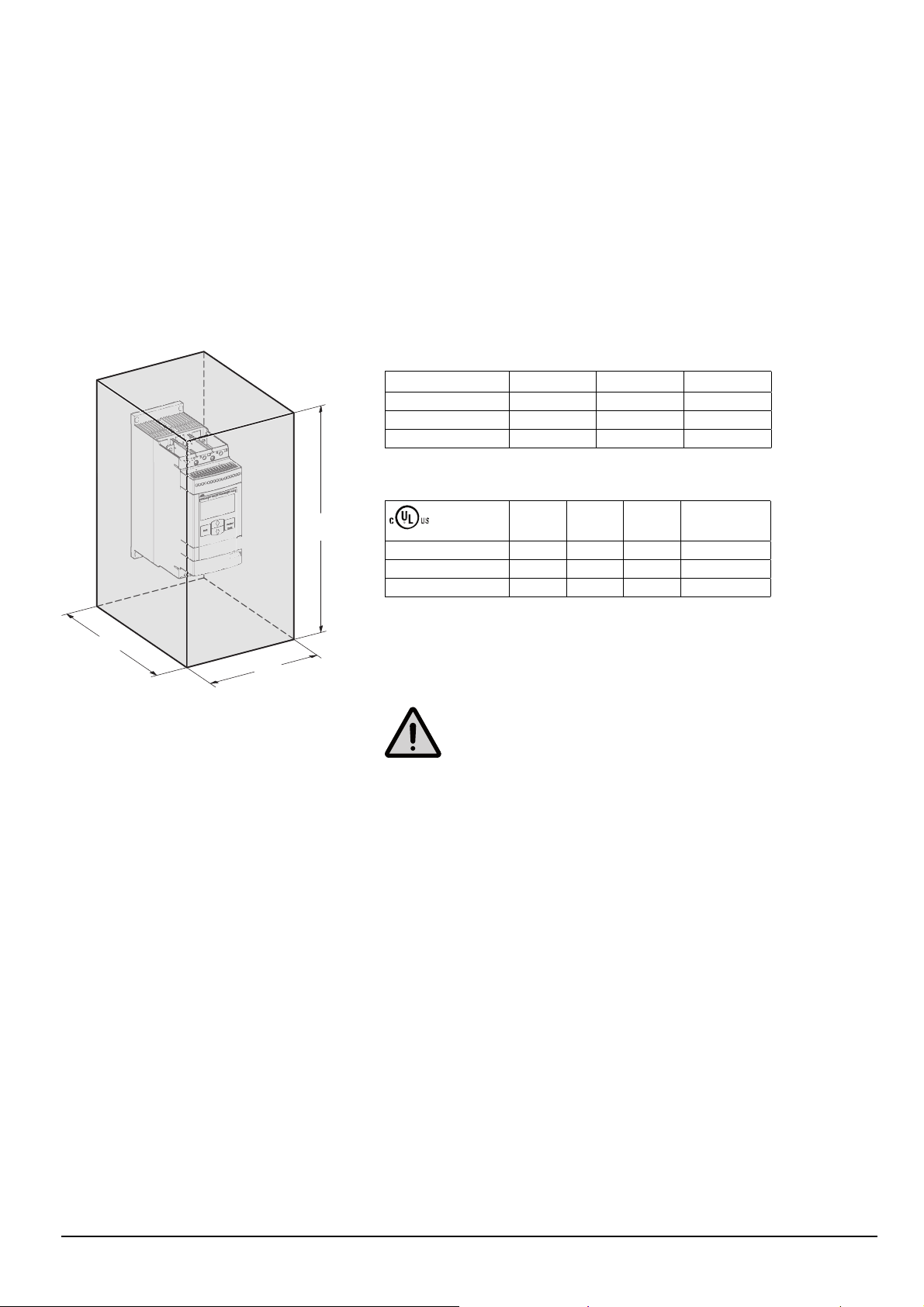
4.2.3 Minimum enclosure size
In applications where the softstarter is installed in an enclosure, the following
minimum enclosure sizes are recommended. Dimensions according to the sketch
in fi gure 4.3.
Table 4.1
IEC
PSE18...PSE105 508 610 305
PSE142...PSE170 762 914 305
PSE210...PSE370 610 762 305
Table 4.2
PSE18...PSE105 20 24 12 1
PSE142...PSE170 30 36 12 2
PSE210...PSE370 30 30 12 2
W (mm) H (mm) D (mm)
W (in) H (in) D (in) min number
of latches
D
W
Figure 4.3: Dimensions minimum enclosure size
Dimensions and drilling plan see Chapter 3 Description.
1SFC132269F0001
Warning!
Using a too small enclosure and/or failure to follow the instructions in other
ways may result in overheating of the PSE Softstarter and operational disturbances.
Softstarters Type PSE18...PSE370 Installation and commissioning manual 1SFC132057M0201 29 Chapter 4
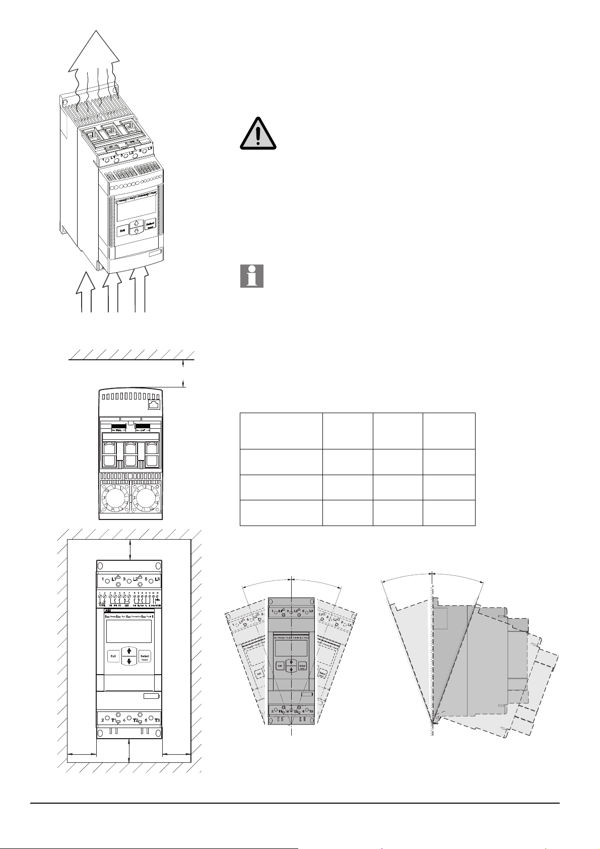
Figure 4.4: Airways
4.2.4 Minimum distance to wall and front
Check that a suffi cient fl ow of air for cooling purposes can circulate from the bot-
tom to the top of the softstarter, and has a free passage away. Figure 4.3.
Warning!
Risk of damage to property. Ensure that no liquids, dust or conductive parts
enter the softstarter.
1SFC132240F0001
Make sure that the distances to the surrounding walls are suffi cient, and that the
mounting angle is within specifi cations shown in fi gure 4.5.
Follow the minimum distance to front and wall, as described in fi gure 4.4 and the
table below.
A
PSE 18-600-70
C
1SFC132243F000
Table 4.3
The values in table 4.3 are minimum distances.
A
(mm
[inch])
PSE18...PSE105 100
[3.937]
PSE142...PSE170 100
[3.937]
PSE210...PSE370 100
[3.937]
30
O
PSE 18-600-70
PSE 18-600-70
30
O
PSE 18-60
0-70
B
(mm
[inch])
10
[0.394]
10
[0.394]
10
[0.394]
30
O
C
(mm
[inch])
20
[0.787]
20
[0.787]
20
[0.787]
30
O
A
BB
Figure 4.5: Minimum distances to wall and front
Softstarters Type PSE18...PSE370 Installation and commissioning manual 1SFC132057M020130 Chapter 4
1SFC132280F0001
1SFC132242F0001
Figure 4.6: Maximum mounting angle
 Loading...