


Softstarters
1SFC132081M0201 EN, Rev K
Softstarters Type PSTX30...PSTX1250
Installation and commissioning manual

Original instruction
This is the Installation and commissioning manual for Softstarters Type PSTX30…PSTX1250.
Document number: 1SFC132081M0201
Revision: K
Issue date: 2017-09-07
Data can be changed without notice.
We reserve all rights to this document, even in the event that
a patent is issued and a different commercial proprietary right
is registered. Improper use, in particular reproduction and dissemination to third parties, is not permitted.
This document is written carefully. If you find an error, please
notify us as soon as possible.
The data contained in this manual is intended solely for the
product description and is not to be deemed to be a statement of guaranteed properties. In the interests of our customers, we constantly seek to ensure that our products are
developed to the latest technological
Author’s address:
ABB AB
Control Products
SE-721 61 VÄSTERÅS, Sweden
www.abb.com/lowvoltage
© Copyright 2017. All rights reserved. Data can be changed
without notice.
Read this first
Warning and safety
Thank you for selecting this ABB PSTX Softstarter.
Carefully read and make sure that you understand all
instructions before you install, connect, configure the
Softstarter.
This manual is intended for installation and advanced
usage of the PSTX Softstarter. For quick and easy
installation, see 1SFC132082M9901 - Softstarters Type
PSTX30...PSTX1250 User Manual short form. The manual
is available on: http://www.abb.com/lowvoltage
When this manual refers to http://www.abb.com/
lowvoltage: Select the link Control Products, continue
to Softstarters and type in the specified reference in the
search field.
• Only authorized and appropriately trained personnel are
permitted to install and make the electrical connection of
the Softstarter. Obey all laws and regulatons.
• Only authorized personnel are permitted to do service and
repair on the Softstarter.
• Unauthorized repair will have an effect on the warranty.
• ABB personnel must obey the instructions in ABB CISE
15.4.
• This manual is a part of the PSTX Softstarter.
Always keep this manual available when you work with
the PSTX Softstarter.
• Examine the Softstarter and the package when
you unpack your new PSTX Softstarter. If there are
damages, please speak to the transportation company
or the ABB reseller/office immediately.
Safety notes
In the manual, these symbols are used
WARNING
General warning symbol indicates the presence of
a hazard which could result in personal injury and
damage to equipment or property.
WARNING
Warning symbol indicates the presence of
hazardous voltage which could result in
personal injury.
General safety information
WARNING
Approved personnel are allowed to install and
make the electrical connection of the Softstarter
in accordance with existing laws and regulations.
WARNING
Examine the Softstarter and the package when
you unpack your new PSTX Softstarter. If there
are damages, please speak to the transportation
company or the ABB reseller/office immediately.
WARNING
Only approved personnel are allowed to do
service and repair.
Note: not approved repair can effect the warranty.
Legal Disclaimer
The PSTX Softstarter is designed to be connected to
and to communicate information and data via a network
interface. It is customers sole responsibility to provide
and continuously ensure a secure connection between
the product and your network or any other network (as
the case may be) and to establish and maintain any
appropriate measures (such as but not limited to the
installation of firewalls, application of authentication
measures, encryption of data, installation of anti-virus
programs, etc) to protect the PSTX Softstarter, the
network, its system and the interface against any kind
of security breaches, unauthorized access, interference,
intrusion, leakage and/or theft of data or information.
ABB Ltd and its affiliates are not liable for damages
and/or losses related to such security breaches, any
unauthorized access, interference, intrusion, leakage and/
or theft of data or information.
WARNING
Approved personnel are allowed to install and
make the electrical connection of the Softstarter
in accordance with existing laws and regulations.
INFORMATION
Information sign tells the reader important facts
and conditions.
Changes to data in this manual can be applied without notice.


Softstarters Type PSTX
Installation and commissioning manual
1 Introduction
2 Quick start
3 Description
4 Installation
5 Connection
6 Human machine interface (HMI)
7 Functions
8 Communication
9 Maintenance
10 Troubleshooting
11 Wiring and application diagrams
12 Third par ty licenses
13 Revision
14 Index
11
2
3
4
5
6
7
8
9
10
11
12
13
14


1 Introduction
1.1 Documentation for Softstarter PSTX30...PSTX12500
8
1.1.1 Installation and commissioning manual
1.2 Intended audience 9
1.3 Revision notes and other documents 9
1.4 Acronyms and abbreviations 9
1
1SFC132081M0201 | Installation and commissioning manual | Introduction 7

This chapter gives an introduction to the Softstarter
documentation manuals and its chapters, releases,
intended audience and it tells about concepts.
1.1.1 Installation and commissioning
manual
This manual, “Softstarters Type PSTX30...PSTX1250
Installation and commissioning manual”, contains
instructions on how to install, commission and maintain
1.1 Documentation for Softstarter
PSTX30...PSTX1250
1
For the Softstarter types PSTX30...PSTX1250, these
manuals and catalogs are available:
1SFC132081M0201
the Softstarter. It gives procedures for mechanical and
electrical installation, and installation of communication
devices. It also gives information abouts energizing,
settings and configuration.
To start quickly, see chapter 2 Quick start
or use the short form manual (1SFC132082M9901).
For chapter content,
see Table 2 Chapter contents below:
This document. Installation and commissioning manual
(English version). See chapter 1.1.1 Installation and
commissioning manual more information.
1SFC132082M9901
Installation and commissioning manual - Short form.
See chapter 1.1.2 Installation and commissioning
manual - Short form for more information.
1SFC132009C0201
Catalog Softstarters Type PSTX and PSTB.
These documents are available online in PDF format.
A printed version of the “Installation and commissioning Short form” is included with the Softstarter.
These manuals are available as online PDF-files:
Table 1 Languages
Document ID Language
1SFC132081M1301 AR Arabic
1SFC132081M2001 ZH Chinese
1SFC132081M4601 CS Czech
1SFC132081M0101 DE German
1SFC132081M0201 EN English
1SFC132081M0701 ES Spanish
1SFC132081M1801 FI Finnish
1SFC132081M0301 FR French
1SFC132081M0901 IT Italian
1SFC132081M3101 NL Dutch
1SFC132081M4001 PL Polish
1SFC132081M1601 PT Portuguese
1SFC132081M1101 RU Russian
1SFC132081M3401 SV Swedish
1SFC132081M1901 TR Turkish
Table 2 Chapters contents
Chapters Description
1. Introduction Introduces the reader to this manual.
2. Quick start Contains information for quick installation of
3. Description Gives a description of the Softstarter with
4. Installation Contains information of the delivery, how to
5. Connection Contains instructions to make the
6. Human-Machine
Interface
7. Functions Gives a description of all functions of the
8. Communication Gives a description of the communication
9. Maintenance Gives a description of the necessary
10. Troubleshooting Contains instructions to find and correct the
11. Wiring diagrams Contains electrical and application diagrams
12. Third party
Licenses
13. Revision Shows all revisions of the manual
14. Index Index of the content of this manual
the Softstarter and get it into operation.
specifications and a list of functions.
unpack and install the Softstarter.
electrical connections, and connections for
communication devices.
Gives a description of the Human-Machine
Interface.
Gives a description of all settings and
navigation of the menu systems.
Softstarter, with their minimum, maximum
and default values. This chapter is intended
for the experienced user.
ports of the Softstarter.
maintenance and how to do it.
most common errors.
for the Softstarter.
3’rd party licenses used by Softstarter
1.1.2 Installation and commissioning
manual - Short form
The “Softstarters Type PSTX30...PSTX1250 Installation
and commissioning manual - Short form” contains brief
information about the Softstarter:
These documents can be found at:
www.abb.com/lowvoltage. Select the link Control
Products on the site, and then continue to Softstarters.
-Installation
-Electrical connections
-Basic functions
-Troubleshooting
The short form contains the languages shown in
Table 1 Languages. The short form has document ID
1SFC132082M9901.
8 Introduction | Installation and commissioning manual | 1SFC132081M0201

1.2 Intended audience
1.2.1 General
The Installation and commissioning manual is intended for
authorized installation, commissioning, and maintenance
personnel.
1.2.2 Requirements for personnel
The installation personnel must have a basic knowledge
in how to handle electrical equipment. The commissioning
and maintenance personnel must have good experience
in how to use electrical equipment. ABB personnel must
obey the instructions in ABB CISE 15.4.
1.3 Revision notes and other
documents
1
For latest information on revisions and other documents
related to the PSTX Softstarters, please see
www.abb.com/lowvoltage. Select the link Control
Products on the site, and then continue to Softstarters.
1.4 Acronyms and abbreviations
Table 3 Acronyms and abbreviations
Acronym/
Abbreviation
BP Bypass
DOL Direct-on-line
EOL Electronic overload
FB Fieldbus
FBP Fieldbus Plug
HMI Human-Machine Interface
I
e
IT Information Technology
LED Light Emitting Diode
PCBA Printed Circuit Board Assembly
PLC Programmable Logic Controller
PTC Positive Temperature Coefficient
SC Short Circuit
SCR Silicon Controlled Rectifier (thyristor)
TOR Top of Ramp (full voltage/Full-On)
U
c
U
e
U
s
*) For definition see IEC 60947-1 edition 5.0
Description
Rated operation current
Rated control circuit voltage, used for
controlling the Softstarter. *
Rated operation voltage on the motor (3 phase
main voltage feeding the motor). *
Rated control supply voltage, feeding the
electronics in the Softstarter. *
1SFC132081M0201 | Installation and commissioning manual | Introduction 9

1
10 Introduction | Installation and commissioning manual | 1SFC132081M0201

2 Quick start
2.1 Connection
12
2.2 Configuration
14
2.2.1 Basic set-up 14
2.2.2 Application set-up 14
2.3 How to start/stop the motor
15
2
1SFC132081M0201 | Installation and commissioning manual | Quick start 11
This chapter is a short guide on how to connect,
1SFC132081M0201
1SFC132081M0201
1SFC132081M0201
configure and start the Softstarter in an easy way.
This product was carefully manufactured and tested, but
damage can occur during transportation. Therefore, obey
these instructions:
WARNING
Dangerous voltage: Can cause death or serious
injury. Always set the power switch to off and lock
out all power to this device before you start to
2
work on the equipment.
1 2
WARNING!
Installation of electrical connections must be done by
authorized personnel. Obey all laws and regulations.
PSTX
PSTX
WARNING!
Before you connect the Softstarters PSTX30...
PSTX170 to the operation voltage for the first time,
apply control supply voltage to open the bypass
relays. (see 2.1 Connection). This is necessary to
avoid an accidental start of the equipment while it is
connected to operation voltage.
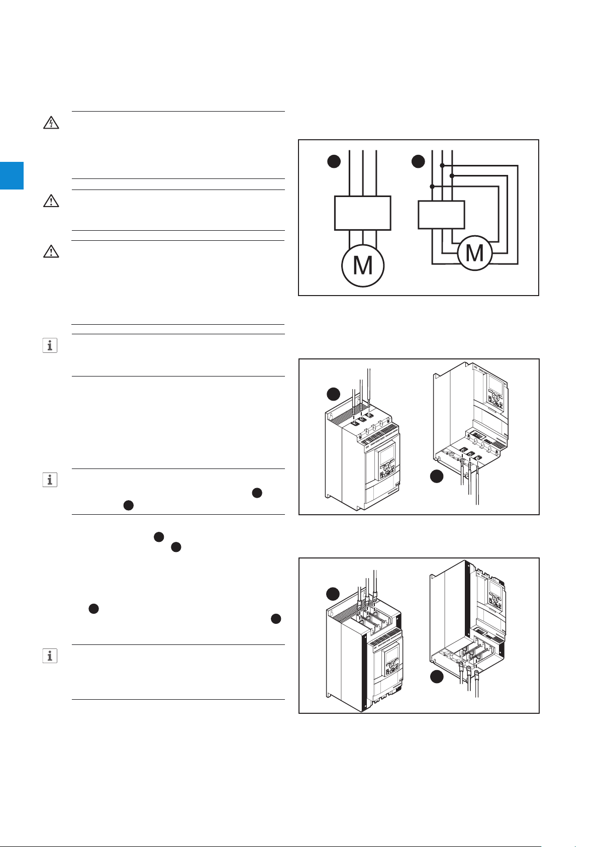
Figure 2.1
In Line (1) and Inside Delta (2) connection
INFORMATION
ABB personnel must obey the instructions in
ABB CISE 15.4.
2.1 Connection
1. To install the Softstarter
see chapter 4 Installation.
INFORMATION
You can connect PSTX Softstarters In Line 1 and
Inside Delta 2, see Figure 2.1.
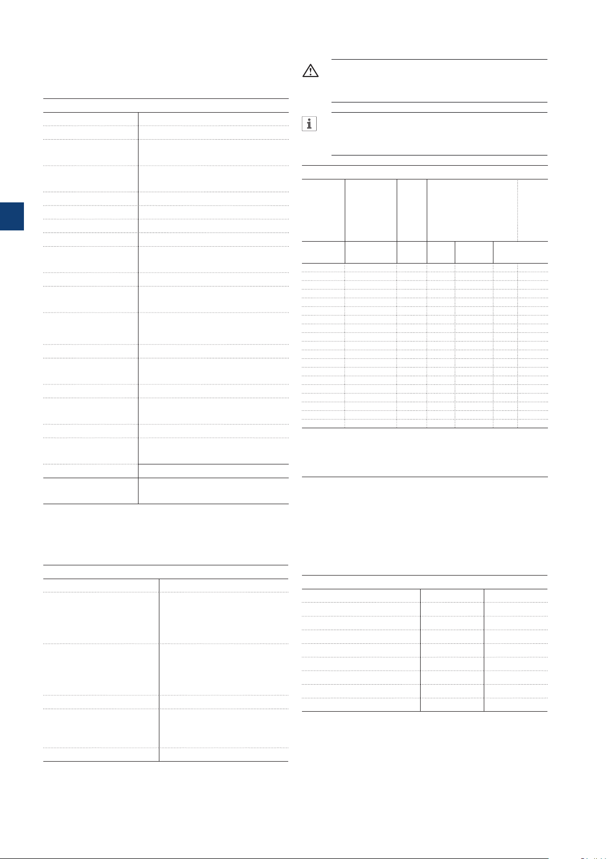
2. Connect the main circuit: terminals 1L1 - 3L2 5L3 to the line side 1, and terminals 2T1 - 4T2
- 6T3 to the motor side 2, see Figure 2.2.. Use
wire connection for PSTX30...105, see Figure 2.2
and terminal connection for PSTX142...570, see
Figure 2.3.
3. Connect the line side to terminals 1L1, 3L2, 5L3.
see 1 and Figure 2.2. Connect the motor to
terminals 2T1, 4T2, 6T3 on the motor side, see 2
Figure 2.2 and Figure 2.3.
5L3
3L2
1L1
1
Figure 2.2
Terminal connection clamps
1
Line side
5L3
3L2
1L2
Line side
2
Motor side
2T1
4T2
6T3
INFORMATION
Use only wires of the same dimension when you
connect 2 wires to each terminal. (Possible for
PSTX30...105 only).
4. Connect the control supply voltage (100-250V
50/60Hz) to terminal 1 and 2.
5. Connect the functional ground (terminal 22), to a
ground point close to the Softstarter,
see Figure 2.4.
12 Quick start | Installation and commissioning manual | 1SFC132081M0201
Figure 2.3
Terminal connection bars
4T2
Motor side
6T3
2
2T1

INFORMATION
1SFC132081M0201
1SFC132081M0201
1SFC132081M0201
1SFC132081M0201
The ground is not a protective ground, it is a
functional ground. The maximum length of the
ground cable is 0.5 m. Connect the ground cable
to the installation plate were the Softstarter is
attached. The installation plate must also be
grounded.
INFORMATION
Do not use functional ground in IT-networks, commonly
found in for instance marine applications.
6. Look at the diagram, see Figure 2.7, and connect
the start/stop circuits: terminal 13, 14, 18, 19 and
20/21, with the internal 24V DC terminal. When
you use internal 24 V DC (terminals 20 or 21), the
terminals 18 and 19 must be connected to each
other. For external control circuit voltage,
see chapter 5.1.2.3 Start and Stop - terminals
13, 14, 18, 19, 20, 21.
WARNING
Use 24V DC only when you connect terminal 13, 14,
15, 16 and 17. Other voltages can cause damage
to the Softstarter and the warranty will no longer be
valid. For more information about terminal 15, 16 and
17, see chapter 5.1.2.4 Programmable inputs -
terminals 15, 16 and 17.
7. Connect terminals 4, 5, 6, 7, 8, 9, 10, 11 and
12 to use the signal output relays. These are
potential-free contacts for maximum 250 V AC, 1.5
A AC-15 and 30 V DC, 5 A DC-12.
See Figure 2.5.
8. Make sure that the operation voltage and control
supply voltage agree with the Softstarter ratings.
9. Set the control supply voltage switch to ON.
10. The green Ready LED is constant lit if the following
conditions are fulfilled:
- Control supply voltage is detected
- Mains three phase voltage is detected
- Mains frequency is within range (40-72Hz)
- Motor connection is detected
- Phase sequence is detected
- No events are active
- Enable signal is active
- If the max nbr of starts per hour function is
enabled and set to stop manual or stop automatic,
the remaining time to start counter (which can be
shown in the HMI homeview) has to be zero
Otherwise the ready LED is flashing, see Figure
2.6.
11. The language settings appear on the screen.
Select your language and push the selection soft
key “OK”. The HMI now downloads the language
data from the Softstarter. This can take some
minutes. When this is done the HMI shows the
Home view.
Figure 2.4
Functional ground, terminal 22
L1
L2
L3
N
KM1
1L13L2 5L3
2T14T2 6T3
UVW
M
3
LN
StartStop
Star 24 V DCt
Stop
Figure 2.7
Circuit diagram (Fuse and contactor version)
L1
L2
L3
N
1L13L2 5L3
2T14T2 6T3
UVW
M
3
LN
StartStop
Star 24 V DCt
Stop
Figure 2.5
Circuit diagram ( MCCB version)
L
N
100-250V
50/60 Hz K4 K4 K4
StartStopResetIn1In2 DGND DND +24V GND
PSTX
22
2014 18 1913
19 201815 16 17141321 21
22
2014 18 1913
19 201815 16 17141321 21 22
2
22
121110987654
22
121110987654
12. Configure applicable parameters as given in
chapter 7 Functions or use the assistants as
given in chapter 2.2 Configuration.
1SFC132081M0201 | Installation and commissioning manual | Quick start 13
Figure 2.6
Flashing “Ready” LED

2.2 Configuration
For a quick configuration of the Softstarter, use the
Assistants menu.
The Assistants menus are divided into:
• Basic set-up
- The Basic set-up menu is divided into 4 steps:
1. Language
2. Date and time
3. Motor data
4. System configuration
2
• Application set-up
- The Application set-up is divided into 3 steps:
1. Application set-up
2. Keep/Change values
3. Tune settings
2.2.1 Basic set-up
You see this set-up when you start the Softstarter. To
disable this set-up, see step 6 below.
1. Find the Assistants menu by pushing “Menu”.
Scroll to Assistants with the Navigation keys. Push
“Select” to enter the Assistants menu.
2. Scroll to the Basic set-up menu with the
Navigation keys. Push “Select” to enter the
menu.
3. The Basic set-up starts with step 1 of 5,
Language. Push “Edit” to change language.
Use the Navigation keys to select language and
then push “Save”.
4. Push to enter step 2(5), Date and time. Push
“Edit” and use the Navigation keys to edit date
and time, then push “Save”.
5. Push to enter step 3(5), Motor data.
Push “Edit” to change the Motor rated current
Ie. Use the Navigation keys to change the value
and then push “Save”.
2.2.2 Application set-up
1. Find the Assistants menu from the Home view by
pushing “Menu”. Scroll to Assistants with the
Navigation keys. Push “Select” to enter the
Assistants menu.
2. Scroll to the Application set-up menu with the
Navigation keys and then enter the menu by
pushing “Select”.
3. The Application set-up will start with step 1,
Application type. Scroll to the appropriate
application type and then push “Select”. For
a full Application list, see chapter 7.25 Complete
parameter list.
4. Push to enter step 2, Values. You can select
“Keep actual values” or “Change to recommended
values”. Scroll to the selection of your choice and
Push “Select” to apply.
WARNING!
Note that your saved parameter values are lost if you
select “Change to recommended values”.
5. Push to enter step 3, Tune settings. In most
cases the recommended values are sufficient, but
sometimes fine tuning is necessary. For fine tuning,
push “Edit” and then use the navigation keys
to set:
-Start ramp time: 1 - 120s
-Stop ramp time: 1 - 120s
-Start ramp initial level: 10 - 99%
-Stop ramp end level: 10 - 99%
-Current limit level: 1.5 - 7.5 x Ie
-Start mode: Voltage ramp, Torque ramp or Full
voltage start
-Stop mode: No ramp, Voltage ramp, Torque ramp,
Dynamic brake
6. Push and then push “Done” to finish the
Application set-up. If necessary, fine tuning can
also be done in the Parameters menu.
6. Push to enter step 4(5), System configuration.
Here you can set if the Softstarter enters the Basic
set-up at power on or not. Use the Navigation keys
to select Yes or No and then push “Save”.
7. Push to enter step 5(5) and then Push
“Done” to finish the Basic setup. For more
settings, enter Application set-up.
14 Quick start | Installation and commissioning manual | 1SFC132081M0201

2.3 How to start/stop the motor
WARNING
Dangerous voltage: Can cause death or serious
injury. Always set the power switch to off and lock
out all power to this device before you start to
work on the equipment.
WARNING
Approved personnel are allowed to install and
make the electrical connection of the Softstarter
in accordance with existing laws and regulations.
WARNING!
Before you connect the Softstarters PSTX30...
PSTX170 to the operation voltage for the first time,
apply control supply voltage to open the bypass
relays. (see 2.1 Connection). This is necessary to
avoid an accidental start of the equipment while it is
connected to operation voltage.
INFORMATION
ABB personnel must obey the instructions in
ABBCISE15.4.
2
1. Set the operation voltage switch to ON.
2. To start the Softstarter from the keypad, push
the R/L-key to select local control, then push the
Start key on the keypad. Push Stop to stop the
Softstarter
3. To start from hard wire control, push the R/L-key
to select hard wire control, then push the remote
Start key. Push Stop to stop the Softstarter.
1SFC132081M0201 | Installation and commissioning manual | Quick start 15

2
16 Quick start | Installation and commissioning manual | 1SFC132081M0201

3 Description
3.1 Overview
18
3.1.1 Operation functions 18
3.1.2 Protection functions 18
3.1.2.1 User defined protection 19
3.1.3 Warning functions 19
3.1.4 Fault detection functions 19
3.1.5 Softstarter overview 20
3.1.6 Type designation 21
3.1.7 Environmental influence 21
3.1.8 Specifications 21
3.2 Technical data
22
3.2.1 General 22
3.2.2 Technical data for external keypad 22
3.2.3 Semi-conductor fuses 22
3.2.4 Weights 22
3.2.5 Softstarter ratings 23
3.2.6 Dimensions 25
3
1SFC132081M0201 | Installation and commissioning manual | Description 17

This chapter gives a description of the Softstarter in
general, specifications and available components and
spare parts.
3.1 Overview
3.1.1 Operation functions
Available functions are listed below:
• Voltage start ramp
• Voltage stop ramp
• Torque start ramp
The PSTX Softstarter has the latest technology for
soft start and soft stop of squirrel cage motors. The
Softstarter has multiple advanced motor protection
features as standard.
3
WARNING
If using the Rated Operational Voltage U
/N) as source for Control Supply Voltage Us make
sure to not exceed Us 250V AC,50/60Hz.
Bypass
Softstarter range PSTX30...1250 have integrated bypass
components.
User interface
The keypad on the front has Navigation keys, Selection
soft keys, Start and Stop keys, Local or Remote key,
Information key and a clear information screen. You can
select 15 user languages.
You can control the Softstarter in 3 different ways:
• Hardwire inputs control
• Keypad control (either attached to the Softstarter front
or detached and connected with the cable included)
• Fieldbus communication interface (by built in Modbus,
Anybus module or the FieldBus Plug with adapter)
You can use only one type of control at the same time.
Default selection is hardwire inputs control.
(Phase
e
• Torque stop ramp
• Full voltage start
• No ramp
• Stand-still brake
• Current limit
• Kick start
• Slow speed
• Motor heating
• Sequence start
• Automatic restart
3.1.2 Protection functions
The PSTX Softstarter has protection functions to
protect the Softstarter, motor and other equipment. All
protections can have automatic reset or manual reset.
You can enable or disable the protection.
Available protections are listed below:
• EOL protection
• Locked rotor protection
• Phase reversal protection
INFORMATION
Keypad control has the highest priority and
overrides all other control methods.
Fans
The integrated fans for cooling work during ramping
(start/stop) and when the heatsink temperature is too
high. A thermistor monitors the temperature.
• Current imbalance protection
• Overvoltage protection
• Under voltage protection
• Ground fault protection
• Voltage imbalance protection
• Voltage outputs protection
• External thermal sensor - PT100 protection
• External thermal sensor - PTC protection
• Power factor underload protection
• Current underload protection
• User defined protection
• Too long current limit protection
• Bypass open protection
• Fieldbus failure protection
• Extension IO failure protection
• HMI failure protection
• Max number of starts
18 Description | Installation and commissioning manual | 1SFC132081M0201

• Frequency range protection
• Phase reversal protection
• Too long start time protection
• Auto restart protection
3.1.2.1 User defined protection
3.1.4 Fault detection functions
The Softstarter has a number of fault detection functions
to signal malfunction at Softstarter, motor or power
network level. The Softstarter identifies external and
internal faults. The user cannot disable fault detection
functions except for Emergency mode, chapter 7.20.1.
You can use your own specified protection, with the
programmable digital input and an external device/sensor.
The protection operates when the input signal comes at
high level (fieldbus or physical I/O).
3.1.3 Warning functions
The Softstarter has warning functions for potential risks,
that operate before a protection function operates.
A warning cannot stop the Softstarter. A reset of a
warning is not necessary.
You can change the warning level and other parameters
for the warning functions. Warnings are stored in the
event list.
Available warnings are listed below:
• Current imbalance warning
• Overvoltage warning
Available faults are listed below:
• Phase loss fault
• High current fault
• Low supply voltage fault
• Bad network fault
• Thyristor overload fault
• Short circuit fault
• Shunt fault
• Unspecified fault
• Heatsink overtemperarure fault
• Open circuit thyristor fault
• Faulty usage
• Connection fault
3
• Under voltage warning
• EOL time-to-trip warning
• EOL warning
• Total Harmonic Distortion (THD) warning
• Voltage imbalance warning
• Power factor underload warning
• Current underload warning
• Fans fault warning
• Locked rotor warning
• Thyristor overload warning
• Short circuit warning
• Number of starts warning
• Modbus configuration warning
• Phase loss warning
• Motor runtime warning
1SFC132081M0201 | Installation and commissioning manual | Description 19

3.1.5 Softstarter overview
1SFC132081M0201
Change the settings through Keypad and Fieldbus
communication.
Use the keypad to change settings for each parameter
alone or as a selection of default parameters for different
applications.
Most parameters have one possible setting, but some
parameters have extra settings for sequence start. The
default parameter settings are stored in the unit for a
reset to default.
When the fieldbus communication is selected, most
parameters can also be changed from this interface.
3
Overview, See Figure 3.1.
Terminal marking of
control circuits
Supply voltage Us
L
N
100-250V
50/60 Hz K4 K5 K6
Order code
Ready (Green)
Run (Green)
Ready
Run Fault
Technical data
according to
IEC 60 947-4-2
Technical data
according to UL 508
Com1 Com2
Anybus
connection
(Com1)
Fieldbus plug adapter
connection (Com2)
Motor side connection
Figure 3.1
Softstarter overview
3L21L1 5L3
Start StopIn1 In2DGND+24VGND
4T22T1 6T3
In0
PSTX
Protection
Symbol for
Torque control
Screen
Protection (Yellow)
Fault (Red)
Keypad
Mini USB
Country of origin
Utilization code
Approvals
Terminal marking of
control circuits
Line side connection
20 Description | Installation and commissioning manual | 1SFC132081M0201

3.1.6 Type designation
1SFC132081M0201
3.1.8 Specifications
Table 1 Type designation
Designation
(i.e. PSTX370-600-70)
PSTX Softstarter type
370 Current rating
600 Main voltage
70 Supply Voltage
Description
370 = 370A
600 = 208 - 600V 50/60 Hz
690 = 400 - 690V 50/60 Hz
70 = 100 - 250V 50/60 Hz
Type designation, see Figure 3.2.
PSTX-370-600-70
Supply Voltage
70 = 100 - 250V 50/60 Hz
Main voltage
600 = 208 - 600V 50/60 Hz
690 = 400 - 690V 50/60 Hz
Current rating
370 = 370A
Softstarter range
Figure 3.2
Type designation
Table 2 Specifications
General data Description
Degree of protection:
Main circuit
Degree of protection:
Supply and control
circuit
Operating position Vertical at ± 30°
Ambient temperature Storage: -40 °C to +70 °C
Altitude 1000 m (3281 ft.) above sea level without
Pollution degree 3
Relative humidity 5 - 95% (non condensing)
Standards IEC 60529
Standards UL UL508
PTC input IEC 60947-8 Mark A detectors
EMC
Marine approvals Speak to your ABB sales office
PSTX30...105:
IP10
PSTX30...105:
IP20
(-104 °F to 140 °F)
Operation: -25 °C to +60 °C
(-77°F to 104 °F)
De-rating: Above 40 °C (104 F) up to max.
60 °C (140 F) reduce the rated current with
0,8% per °C (0,44% per F).
derating. 1000 - 4000 m (3281 - 13123 ft.)
with derating 0,7%/100 m (0,22%/100ft)
IEC 60947-1
IEC60947-4-2
DIN 44081 and DIN 44082
IEC 60947-4-2 Class A
PSTX142...1250:
IP00
PSTX142...1250:
IP20
1
3
3.1.7 Environmental influence
The product is designed to reduce the effects on the
environment during manufacturing and use of the
product.
Most of the materials used are recyclable. Obey local
laws when you handle and recycle the materials.
You can find further information about used material and
recycling of the product at:
www.abb.com/lowvoltage
The Softstarter is designed for class A equipment.
1
Use of the product in domestic environments can cause
radio interference. If so, it can be necessary to use more
mitigation procedures.
1SFC132081M0201 | Installation and commissioning manual | Description 21
3.2 Technical data
3.2.1 General
Table 3 General
General data Description
24 V output 24 V ± 5% Max 250 mA
Rated insulation voltage, Ui600 V / 690 V
3.2.3 Semi-conductor fuses
WARNING!
Semiconductor fuses must be used to keep the
warranty on the thyristors.
INFORMATION
To achieve a type 2 coordination, semiconductor
fuses must be used.
Rated operation voltage, Ue208-600 / 690 V, 50 / 60 Hz
Rated supply voltage,Us 100-250 V, 50 / 60 Hz
3
Voltage tolerance +10% to -15%
Rated frequency 50 / 60 Hz
Frequency tolerances ± 10%
Rated impulse withstand
voltage
6 kV Operation circuit
4 kV Control and supply circuit
Relay outputs 3 programmable
Number of controlled
3
phases
Inputs Start, stop, 3 programmable inputs
(Digital I/O: In0, In1, In2), temperature
sensor input.
Outputs Relay outputs: K4 K5 K6.
Output relay
250 V AC, Ith = 5A, Ie = 1.5A (AC-15)
performance
Analog output 4-20 mA, 0-20 mA, 0-10 V, 0-10 mA
PTC input 2825 ohm ± 20% switch off resistance
1200 ohm ± 20% switch on resistance
Cooling system Fan
Recommended fuse
Control supply circuit
6 A Delayed
MCB use C characteristics
Communication 3 Fieldbus ports, Extension I/O
Communication
protocols
DeviceNet / Profibus DP / Modbus /
EtherNET/IP / Modbus TCP/ Profinet
Table 5 Fuses ratings and power losses
Current
range
Max
Max fuse raiting - main
1) 2)
circuit
power
Bussmann fuses, DIN43 620
loss at
(Knife)
rated I
e
Power
require-
ments
supply
circuit
Holding
(VA) /
Type A W A Type Size
Pull-in
(VA)
PSTX30 9.0...30.0 0.8 100 170M1567 000 49/51
PSTX37 11.1...37.0 1.2 125 170M1568 000 49/51
PSTX45 13.5...45.0 1.8 160 170M1569 000 49/51
PSTX60 18.0...60.0 3.2 160 170M1569 000 49/51
PSTX72 21.6...72.0 4.7 250 170M1571 000 49/51
PSTX85 22.5...85.0 6.5 315 170M1572 000 49/51
PSTX105 31.8...106.0 10 400 170M3819 1* 49/51
PSTX142 42.9...143.0 18 500 170M5810 2 49/53
PSTX170 51.3...171.0 26 630 170M5812 2 49/53
PSTX210 63.0...210.0 48 630 170M5812 2 56/276
PSTX250 75.0...250.0 68 700 170M5813 2 56/276
PSTX300 90.0...300.0 97 800 170M6812 3 56/276
PSTX370 111.0...370.0 148 900 170M6813 3 56/276
PSTX470 141.0...470.0 99 900 170M6813 3 67/434
PSTX570 171.0...570.0 146 1000 170M6814 3 67/434
PSTX720 216.0...720.0 78 1250 170M8554 3 61/929
PSTX840 252.0...840.0 106 1500 170M6018 3 61/929
PSTX1050 3)315.0...1050.0 165 1800 170M6020 3 68/929
PSTX1250
3) 4)
1)
For the supply circuit 6 A delayed, for MCB use C characteristics.
2)
For inside delta connection the fuses shall be placed inside the delta. Contact ABB for
more information.
3)
170M6019 with fuse rating 1600 A should be used for 690 V version.
4)
For 690 V version, Bussmann fuses are only available for motors with rated current up
to 1150 A.
375.0...1250.0 234 2000 170M6021 3 68/929
You can find more detailed information at:
http://applications.it.abb.com/SOC/
3.2.2 Technical data for external keypad
3.2.4 Weights
Table 4 Technical data for external keypad
Display Display type
Status indicating LEDs Ready: Green
Run: Green
Protection: Yellow
Fault: Red
Ambient temperature Storage: -25 °C to +70 °C (-13 °F
to 158 °F)
Operation: -25 °C to +60 °C
(-13 °F to 140 °F)
Degree of protection IP66
Table 6 Weights
Type Weight in kg Weight in lbs
PSTX30...105 6,1 13,5
PSTX142...170 9,6 21,2
PSTX210...370 12,7 27,9
PSTX470 25.5 55.1
PSTX570 27.5 59.5
PSTX720 ...840 46.2 101.4
PSTX1050 64.5 141.1
PSTX1250 65 143.3
UL approval Type 1
Type 4X
Type 12
Marine approvals Speak to your ABB sales office
22 Description | Installation and commissioning manual | 1SFC132081M0201

3.2.5 Softstarter ratings
PSTX30…1250 Temp ≤ + 40
IEC
Softstarter type Order number Ie range
PSTX30-600-70 1SFA898103R7000 9-30A 7,5 15 18,5 12,5 25 30 30 52
PSTX30-690-70 1SFA898203R7000 9-30A 15 18,5 25 25 30 45 30 52
PSTX37-600-70 1SFA898104R7000 11,1-37A 9 18,5 22 15 30 37 37 64
PSTX37-690-70 1SFA898204R7000 11,1-37A 18,5 22 30 30 37 55 37 64
PSTX45-600-70 1SFA898105R7000 13,5-45A 12,5 22 25 25 37 45 45 76
PSTX45-690-70 1SFA898205R7000 13,5-45A 22 25 37 37 45 59 45 76
PSTX60-600-70 1SFA898106R7000 18-60A 15 30 37 30 55 75 60 105
PSTX60-690-70 1SFA898206R7000 18-60A 30 37 55 55 75 90 60 105
PSTX30...105
PSTX72-600-70 1SFA898107R7000 21,6-72A 18,5 37 45 37 59 80 72 124
PSTX72-690-70 1SFA898207R7000 21,6-72A 37 45 59 59 80 110 72 124
PSTX85-600-70 1SFA898108R7000 25,5-85A 22 45 55 40 75 90 85 147
PSTX85-690-70 1SFA898208R7000 25,5-85A 45 55 75 75 90 132 85 147
PSTX105-600-70 1SFA898109R7000 31,8-106A 30 55 75 55 90 110 106 181
PSTX105-690-70 1SFA898209R7000 31,8-106A 55 75 90 90 110 160 106 181
PSTX142-600-70 1SFA898110R7000 42,9-143A 37 75 90 75 132 160 143 245
PSTX142-690-70 1SFA898210R7000 42,9-143A 75 90 132 132 160 220 143 245
PSTX170-600-70 1SFA898111R7000 51,3-171A 45 90 110 90 160 200 171 300
PSTX170-690-70 1SFA898211R7000 51,3-171A 90 110 160 160 200 257 171 300
PSTX142-170
PSTX210-600-70 1SFA898112R7000 63-210A 59 110 132 102 184 250 210 360
PSTX210-690-70 1SFA898212R7000 63-210A 110 132 184 184 250 315 210 360
PSTX250-600-70 1SFA898113R7000 75-250A 75 132 160 132 220 295 250 430
PSTX250-690-70 1SFA898213R7000 75-250A 132 160 220 220 295 400 250 430
PSTX300-600-70 1SFA898114R7000 90-300A 90 160 200 160 257 355 300 515
PSTX300-690-70 1SFA898214R7000 90-300A 160 200 257 257 355 500 300 515
PSTX210...370
PSTX370-600-70 1SFA898115R7000 111-370A 110 200 257 200 355 450 370 640
PSTX370-690-70 1SFA898215R7000 111-370A 200 257 355 355 450 600 370 640
PSTX470-600-70 1SFA898116R7000 141-470A 132 250 315 250 450 600 470 814
PSTX470-690-70 1SFA898216R7000 141-470A 250 315 450 450 600 800 470 814
PSTX570-600-70 1SFA898117R7000 171-570A 160 315 400 295 540 700 570 987
PSTX470...570
PSTX570-690-70 1SFA898217R7000 171-570A 315 400 560 540 700 960 570 987
PSTX720-600-70 1SFA898118R7000 216-720A 200 400 500 355 710 880 720 1247
PSTX720-690-70 1SFA898218R7000 216-720A 400 500 710 710 880 1200 720 1247
PSTX840-600-70 1SFA898119R7000 252-840A 250 450 600 450 800 1000 840 1455
PSTX720...840
PSTX840-690-70 1SFA898219R7000 252-840A 450 600 800 800 1000 1400 840 1455
PSTX1050-600-70 1SFA898120R7000 315-1050A 315 560 730 500 1000 1250 1050 1810
PSTX1050-690-70 1SFA898220R7000 315-1050A 560 730 1000 1000 1250 1700 1050 1810
PSTX1250-600-70 1SFA898121R7000 375-1250A 400 710 880 670 1200 1500 1250 2160
PSTX1050...1250
PSTX1250-690-70 1SFA898221R7000 375-1250A 710 880 1200 1200 1500 2000 1250 2160
when connected In Line
220-
380-
230V
400V 500V 690V
kW kW kW kW kW kW kW kW A A
°
Motor power
C (104 °F), 4 * Ie in 10 sec.
when connected Inside Delta
220230V
Motor power
380-
400V 500V 690V In Line
Rated current
Ie
Inside
Delta
3
1) All data for 40°C ambient. Above 40°C (104 F) up to max.
40°C (140 F) reduce the rated current with 0,8% per 40°C
(0,44% per F).
1SFC132081M0201 | Installation and commissioning manual | Description 23

PSTX30…1250 Temp ≤ + 40
°
C (104 °F), 4 * Ie in 10 sec.
Softstarter type Order number
Motor power
when connected In Line
220240V
440480V
208V
hp hp hp hp hp hp hp hp A A
550600V 208V
Motor power
when connected Inside Delta
220-
440-
240V
480V
Rated current
550-
600V In Line
Ie
Inside
Delta
PSTX30-600-70 1SFA898103R7000 7,5 10 20 25 10 15 30 40 28 48
PSTX30-690-70 1SFA898203R7000 20 25 30 40 28 48
PSTX37-600-70 1SFA898104R7000 10 10 25 30 15 20 40 50 34 58
PSTX37-690-70 1SFA898204R7000 25 30 40 50 34 58
PSTX45-600-70 1SFA898105R7000 10 15 30 40 20 25 50 60 42 72
PSTX45-690-70 1SFA898205R7000 30 40 50 60 42 72
PSTX60-600-70 1SFA898106R7000 20 20 40 50 30 40 75 100 60 103
PSTX60-690-70 1SFA898206R7000 40 50 75 100 60 103
PSTX30...105
PSTX72-600-70 1SFA898107R7000 20 25 50 60 30 40 75 100 68 117
3
PSTX72-690-70 1SFA898207R7000 50 60 75 100 68 117
PSTX85-600-70 1SFA898108R7000 25 30 60 75 40 50 100 125 80 138
PSTX85-690-70 1SFA898208R7000 60 75 100 125 80 138
PSTX105-600-70 1SFA898109R7000 30 40 75 100 60 60 150 150 104 180
PSTX105-690-70 1SFA898209R7000 75 100 150 150 104 180
PSTX142-600-70 1SFA898110R7000 40 50 100 125 75 75 150 200 130 225
PSTX142-690-70 1SFA898210R7000 100 125 150 200 130 225
PSTX170-600-70 1SFA898111R7000 50 60 125 150 75 100 200 250 169 292
PSTX170-690-70 1SFA898211R7000 125 150 200 250 169 292
PSTX142-170
PSTX210-600-70 1SFA898112R7000 60 75 150 200 100 125 250 300 192 332
PSTX210-690-70 1SFA898212R7000 150 200 250 300 192 332
PSTX250-600-70 1SFA898113R7000 75 100 200 250 150 150 350 450 248 429
PSTX250-690-70 1SFA898213R7000 200 250 350 450 248 429
PSTX300-600-70 1SFA898114R7000 100 100 250 300 150 200 450 500 302 523
PSTX300-690-70 1SFA898214R7000 250 300 450 500 302 523
PSTX210...370
PSTX370-600-70 1SFA898115R7000 125 150 300 350 200 250 500 600 361 625
PSTX370-690-70 1SFA898215R7000 300 350 500 600 361 625
PSTX470-600-70 1SFA898116R7000 150 200 400 500 250 300 600 700 480 830
PSTX470-690-70 1SFA898216R7000 400 500 600 700 480 830
PSTX570-600-70 1SFA898117R7000 200 200 500 600 300 350 700 800 590 1020
PSTX570-690-70 1SFA898217R7000 500 600 700 800 590 1020
PSTX470...570
PSTX720-600-70 1SFA898118R7000 250 300 600 700 400 500 1000 1200 720 1240
PSTX720-690-70 1SFA898218R7000 600 700 1000 1200 720 1240
PSTX840-600-70 1SFA898119R7000 300 350 700 800 500 600 1200 1500 840 1450
PSTX840-690-70 1SFA898219R7000 700 800 1200 1500 840 1450
PSTX720...840
PSTX1050-600-70 1SFA898120R7000 400 450 900 1000 600 700 1500 1900 1062 1830
PSTX1050-690-70 1SFA898220R7000 900 1000 1500 1900 1062 1830
PSTX1250-600-70 1SFA898121R7000 400 500 1000 1200 800 900 1800 2000 1250 2160
PSTX1250-690-70 1SFA898221R7000 1000 1200 1800 2000 1250 2160
PSTX1050...1250
4 * Ie in 10 sec
Ordering data according to UL (40°C ambient)
24 Description | Installation and commissioning manual | 1SFC132081M0201
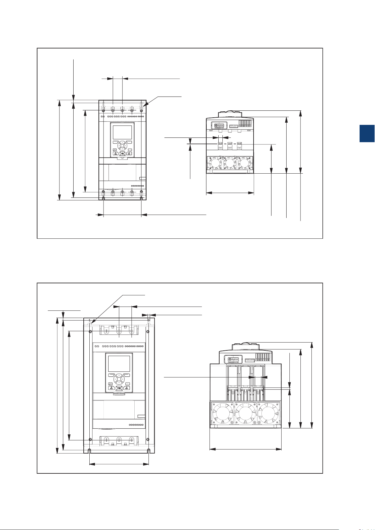
3.2.6 Dimensions
197.5 mm (7,7 in)
90,5 mm (3,6 in
178.8 mm (7 in)
1SFC132081M0201
1SFC132081M0201
PSTX30...105
30 mm (1,2 in) 4x
Ø14 (2x)
314 mm (12,4 in)
298,5 mm (11,7 in) 7,5 mm (0,3 in)
258 mm (10,2 in)
Figure 3.3
Dimensions PSTX30...105
PSTX142...170
7,5 mm (0,3 in)
Ø18 (2x)
13 mm (0,5 in) 6x
119 mm (4,7 in)
35 mm (1,3 in) 4x
6.6 mm (0,2 in) 4x
3
3 mm (0,1 in)
)
150 mm (5,9 in)
377 mm (14,8 in)
303 mm (11,9 in)
360,5 mm (14,1 in)
Figure 3.4
Dimensions PSTX142...170
165 mm (6,5 in)
17,5 mm (0,7 in) 6x
199 mm (7,8 in)
1SFC132081M0201 | Installation and commissioning manual | Description 25
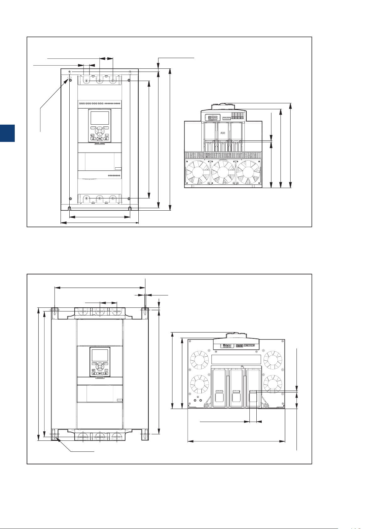
5 mm (0,2 in)
219,6 mm (8,6 in)
107,6 mm (4,2 in)
238,3 mm (9,3 in)
1SFC132081M0201
1SFC132081M0201
58.2 mm (2.3 in) 6x
PSTX210...370
43,7 mm (1,7 in) 4x
19,6 mm (0,8 in) 6x
10,5 mm (0,4 in)
Ø18 (2x)
3
389 mm (15,3 in)
470 mm (18,5 in)
451.2 mm (17,7 in)
5 mm (0,2 in)151 mm (5,9 in)
Figure 3.5
Dimensions PSTX210..370
PSTX470...570
336 mm (13.2 in) 2x
63 mm (2.5 in) 4x
493 mm (19.4 in)
466 mm (18.3 in)
Ø13 (4x)
Figure 3.6
Dimensions PSTX470..570
200 mm (7,9 in)
258 mm (10,2 in)
7 mm (0.2 in) 4x
9 mm (0.3 in)
460 mm (18.1 in)
262.82 mm (10.3 in)
282.15 mm (11.1 in)
260 mm (10,2 in)
279.1 mm (10,9 in)
6 mm (0.2 in) 6x
25 mm (0.9 in) 6x
361 mm (14.2 in)
26 Description | Installation and commissioning manual | 1SFC132081M0201
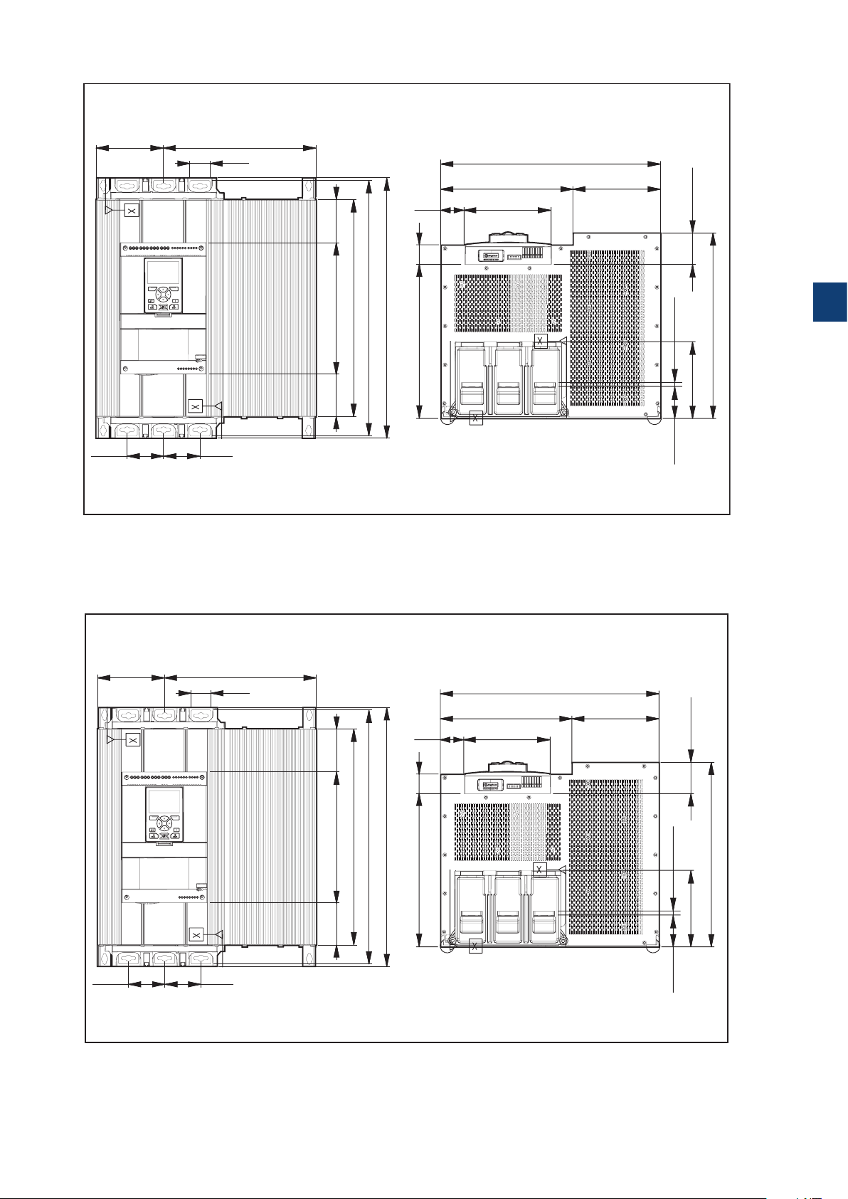
62.6 (6x) mm (in)
62.6 (6x) mm (in)
PSTX720...PSTX840
133.5(2x) mm
(5.2 in)
72(2x) mm
(2.8 in)
72(2x) mm
(2.8 in)
Figure 3.7
Dimensions PSTX720..840
PSTX1050
301.5 mm (11.8 in)
40 (6x) mm
(1.5 in)
(3.37 in)
505 mm (19.8 in)
430 mm (16.9 in)
260 mm (10.2 in) 85.6 mm
(3.3 in)
84.4 mm
46.5 mm
(1.8 in)
39 mm
(1.5 in)
515 mm (20.2 in)
304.5 mm (11.9 in)
435 mm (17.1 in)
172 mm (6.7 in)
173.4 mm (6.8 in)261.6 mm (10.2 in)
62 mm (2.4 in)
3
(0.3 in)
8 (6x) mm
366.5 mm (14.4 in)
152 (2x) mm (5.9 in)
133.5(2x) mm
(5.2 in)
72(2x) mm
(2.8 in)
Figure 3.8
Dimensions PSTX1050
72(2x) mm
(2.8 in)
301.5 mm (11.8 in)
40 (6x) mm
(1.5 in)
(3.37 in)
505 mm (19.8 in)
430 mm (16.9 in)
260 mm (10.2 in) 85.6 mm
(3.3 in)
84.4 mm
46.5 mm
(1.8 in)
39 mm
(1.5 in)
515 mm (20.2 in)
304.5 mm (11.9 in)
435 mm (17.1 in)
172 mm (6.7 in)
173.4 mm (6.8 in)261.6 mm (10.2 in)
62 mm (2.4 in)
(0.3 in)
8 (6x) mm
366.5 mm (14.4 in)
152 (2x) mm (5.9 in)
1SFC132081M0201 | Installation and commissioning manual | Description 27
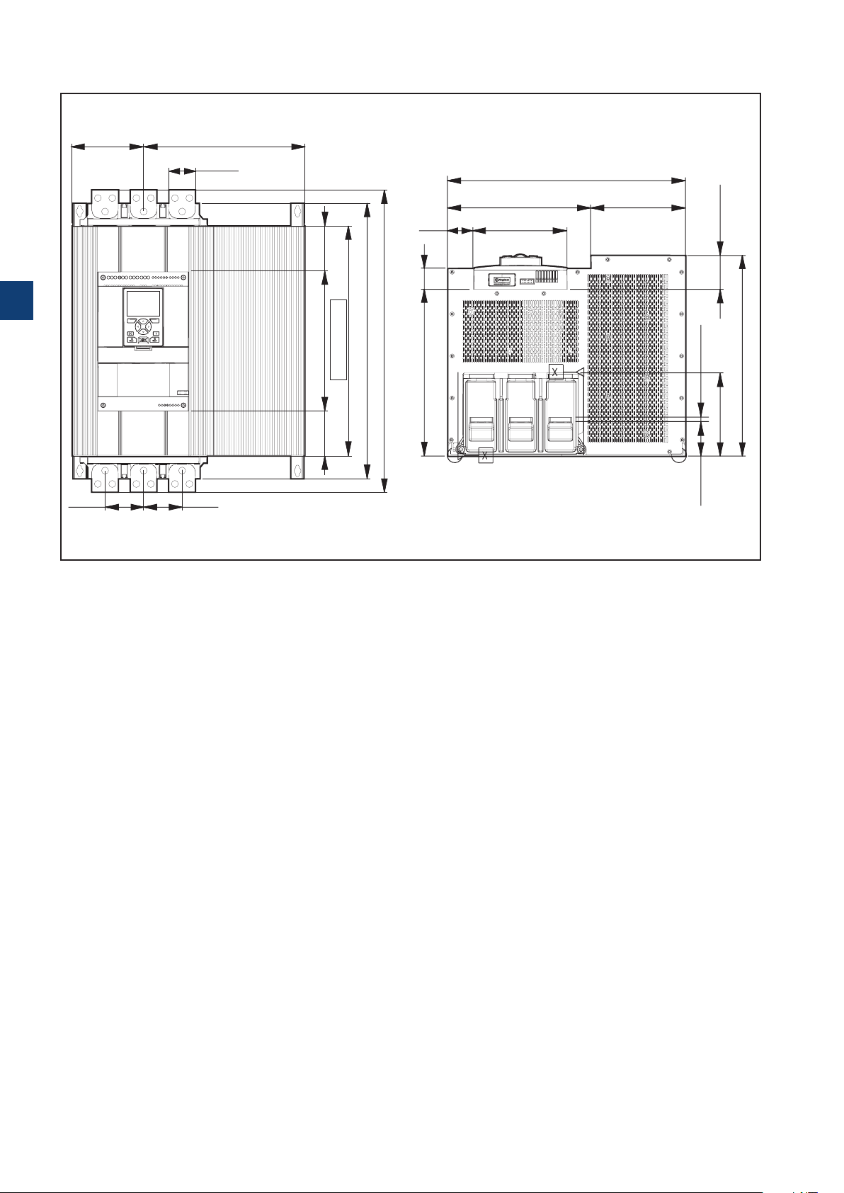
62.6 (6x) mm (in)
PSTX1250
133.5(2x) mm
(5.2 in)
3
301.5 mm (11.8 in)
50 (6x) mm
(1.9 in)
(3.32 in)
84.35 mm
46.5 mm
(1.8 in)
39 mm
(1.5 in)
435 mm (17.1 in)
173.4 mm (6.8 in)261.6 mm (10.2 in)
172 mm (6.7 in)
62 mm (2.4 in)
515 mm (20.2 in)
565 mm (22.2 in)
430 mm (16.9 in)
261.3 mm (10.2 in)
304.5 mm (11.9 in)
(3.32 in)
84.35 mm
(0.3 in)
8 (6x) mm
152 (2x) mm (5.9 in)
366.5 mm (14.4 in)
72(2x) mm
(2.8 in)
72(2x) mm
(2.8 in)
Figure 3.9
Dimensions PSTX1250
28 Description | Installation and commissioning manual | 1SFC132081M0201

3
1SFC132081M0201 | Installation and commissioning manual | Description 29

3
30 Description | Installation and commissioning manual | 1SFC132081M0201
 Loading...