


TRIO-20.0-TL-OUTD-S-US-480-A
ABB TRIO-20.0-TL-OUTD-S-US-480-A, TRIO-20.0-TL-OUTD-S1-US-480, TRIO-20.0-TL-OUTD-S-US-480, TRIO-20.0-TL-OUTD-S1A-US-480, TRIO-20.0-TL-OUTD-S1-US-480-A Product Manual
...
ABB Inverter
TRIO-20.0/27.6-TL-US
EEP125 R-1 Waterworks Division 40
Lancaster, CA 93535

ABB solar inverters
Product manual
TRIO-20.0/27.6-TL-US
(20.0 to 27.6 kW)

- 2 -
T001CV
List of related manuals
TRIO manuals and guides Code (English)
TRIO-20.0_27.6-TL-OUTD-US (-A) BCM.00202.1
Quick Installation Guide
- 3 -
T001CV
IMPORTANT SAFETY INSTRUCTIONS
This manual contains important safety instructions that must be followed during installation and
maintenance of the rapid shutdown system.
SAVE THESE INSTRUCTIONS!
Keep this document in a safe place near the inverter for easy access during installation and
maintenance.
THE INSTALLER MUST READ THIS DOCUMENT IN ITS ENTIRETY BEFORE INSTALLING
THIS EQUIPMENT.
The purpose of this document is to support the qualied technician, who has received training and/
or has demonstrated skills and knowledge in construction, to install and maintain this inverter. This
manual covers only the details concerning the rapid shutdown components and how it is installed in
the allowable ABB string inverters. Information concerning the equipment connected to this product is
available from the respective manufacturers.
Warranty conditions can be found on the Rapid Shutdown product page of the website. NOTE:
Any changes or modications not approved by the manufacturer could void the warranty of this
product.
.
FCC REMARKS
The equipment has been tested and found to comply with the limits for a Class B digital device,
pursuant to Part 15 of the FCC Rules. These limits are designed to provide reasonable protection
against harmful interference in a residential installation. This equipment generates, uses and can
radiate radio frequency energy and, if not installed and used in accordance with the instructions,
may cause harmful interference to radio communications.
However, there is no guarantee that interference will not occur in a particular installation. If
this equipment does cause harmful interference to radio or television reception, which can be
determined by turning the equipment off and on, the user is encouraged to try to correct the
interference by one or more of the following measures:
• Reorient or relocate the receiving antenna.
• Increase the separation between the equipment and receiver.
• Connect the equipment into an outlet on a circuit different from that to which the receiver is
connected.
• Consult the dealer or an experienced radio/TV technician for help.

- 4 -
T001CV
Product Manual
TRIO-20.0/27.6 string inverters
1 - Introduction and safety
2 - Installation location
3 - Mounting and wiring
4 - Operations
5 - Troubleshooting
6 - Maintenance
7 - Appendix
TRIO-20.0-276-TL-OUTD-US(-A) Product manual
BCG.00627.2_AB NA
© Copyright 2015 ABB. All Rights Reserved.

- 5 -
T002TC
Table of Contents
Warnings in this document ...................................................................................................................9
Equipment safety warnings ................................................................................................. 9
Introduction and safety ............................................................................................................................9
General installation warnings............................................................................................10
Assembly warnings ............................................................................................................10
Electrical connection warnings .........................................................................................10
Safety instructions ...............................................................................................................................11
General information ............................................................................................................ 11
Thermal and voltage hazard .............................................................................................. 11
Clothing and protective devices .......................................................................................12
Location of safety notices and labels ...............................................................................12
Appropriate usage ................................................................................................................................12
Conditions of Use ...............................................................................................................12
Environmental Conditions .................................................................................................13
Improper or Prohibited Use ...............................................................................................13
Arc fault detection (AFD) .....................................................................................................................13
Available versions ................................................................................................................................14
Regulatory label ..................................................................................................................15
Transportation and handling ...............................................................................................................17
Lifting ...................................................................................................................................17
Incoming inspection ...........................................................................................................17
Installation location ................................................................................................................................17
Handling the TRIO ...............................................................................................................19
Select the installation location ............................................................................................................20
Environmental check ..........................................................................................................20
Installation position ............................................................................................................21
Mounting and wiring .............................................................................................................................23
Labeled illustration of TRIO ................................................................................................................23
Wall mounting .......................................................................................................................................25
Installation method with flexible conduit .........................................................................26
Installation method with rigid conduit ..............................................................................29
Wiring details ........................................................................................................................................30
AC overcurrent protection .................................................................................................30
Wiring box components .....................................................................................................31
TRIO-XX.X-TL-OUTD-S-US-480 ..........................................................................................32
TRIO-XX.X-TL-OUTD-S-US-480-A ......................................................................................32
TRIO-XX.X-TL-OUTD-S1-US-480........................................................................................33
TRIO-XX.X-TL-OUTD-S1-US-480-A ....................................................................................33
TRIO-XX.X-TL-OUTD-S1A-US-480 .....................................................................................34
TRIO-XX.X-TL-OUTD-S1A-US-480-A .................................................................................34
TRIO-XX.X-TL-OUTD-S1B-US-480 .....................................................................................35
TRIO-XX.X-TL-OUTD-S1B-US-480-A .................................................................................35

- 6 -
T002TC
Independent or parallel configuration of inputs ...............................................................................36
Dual MPPT configuration – independent mode ..............................................................36
Single MPPT configuration – parallel mode (non-AFD models) ....................................37
Setting the input mode switch a01 ...................................................................................37
Connection to the PV field (DC side) ..................................................................................................40
Connection of DC inputs -S model ...................................................................................40
Connection of DC inputs -S1, –S1A, and -S1B models .................................................41
String protection -S1, -S1A, and –S1B models ..............................................................41
Grid output connection (AC side) .......................................................................................................42
Characteristics and sizing of the AC output conductors ...............................................42
Wire installation ..................................................................................................................42
Connection to the AC terminal block ...............................................................................43
Auxiliary grounding electrode conductor (GEC) ............................................................44
Labeled illustration of communication card 09 ................................................................................45
Connections to the communication card .........................................................................46
Serial communication a07 (RS-485)..................................................................................46
Daisy Chain units for connection to a monitoring system ............................................47
Remote on/off a07 ...............................................................................................................48
Auxiliary +5 V output a07 ...................................................................................................49
Configurable relay a05 .......................................................................................................49
Environmental sensors a06 ...............................................................................................50
Auxiliary +24 V service output a06 ...................................................................................51
Setting the country standard and language ......................................................................................51
Saving the country standard and language ....................................................................52
Operations .............................................................................................................................................. 53
Monitoring and data transmission .....................................................................................................53
Types of data available ...................................................................................................... 53
User interface ........................................................................................................................................53
Display and keypad ............................................................................................................54
LED indicators .....................................................................................................................55
Descriptions of symbols and display fields ....................................................................56
Cyclical display of general information............................................................................56
Statistics menu ...................................................................................................................57
Settings menu .....................................................................................................................58
Information menu ................................................................................................................66
Commissioning .....................................................................................................................................67
Configure inverter settings ................................................................................................67
Power ON the inverter ........................................................................................................67
Dynamic behavior of the display during operation ........................................................69
Troubleshooting ..................................................................................................................................... 71
Arc fault detection self-test errors ......................................................................................................71
Obtaining the service level password ................................................................................................72
Resetting the inverter/switchbox association ...................................................................................72
Display messages and error codes ...................................................................................................73
Making a service call ............................................................................................................................86

- 7 -
T002TC
Maintenance ........................................................................................................................................... 87
Routine maintenance ...........................................................................................................................87
Recommended system maintenance .................................................................................................88
Preventative maintenance ...................................................................................................................88
Storage and dismantling .....................................................................................................................89
Appendix .................................................................................................................................................91
System description .............................................................................................................................91
Protective devices within the inverter ................................................................................................92
Ground fault detection and interruption scheme ............................................................................93
Topographic diagram of the equipment ............................................................................................94
Efficiency curves ..................................................................................................................................96
Voltage and temperature derating due to altitude ............................................................................97
Automatic power reduction .................................................................................................................98
MPPT configuration examples ..........................................................................................................102
Environmental sensors ......................................................................................................................103
Connection diagrams for environmental sensors ........................................................104
Technical data and types ...................................................................................................................105
Technical data and types (continued) ..............................................................................................106

- 8 -
T002TC
This page is intentionally blank.

- 9 -
T003CH1
Warnings in this document
This is a list of special safety symbols used in this manual that highlight potential safety risks and/or useful
information. The symbol usage is described below:
CAUTION
The reader should stop, use caution and fully understand the operations
explained before proceeding.
DANGEROUS VOLTAGE
The product works with high voltages. All work on the TRIO must follow
the described documentation and must comply with all prevailing codes and
regulations associated with high voltages.
HOT TEMPERATURE
Some surfaces may become hot; wear appropriate personal protective
equipment (PPE) when working with this product.
UL1741 Standard for Safety for Inverters, Converters, Controllers and
Interconnection System Equipment for use with Distributed Energy
Resources. CSA-C22.2 No. 107.1-01 - General Use Power Supplies.
Equipment safety warnings
In addition to the safety and hazard symbols, the following symbols are also used in this
installation guide
Equipment Ground, protective earth
Alternating current (AC)
ø
Phase
Direct current (DC) Grounding (earth)
1
Introduction and safety
T004CC1
- 10 -
1- Introduction and safety
General installation warnings
The TRIO transformerless inverter is designed and tested according to international safety
requirements (UL1741/IEEE1547); however, certain safety precautions must be observed when
installing and operating this inverter. Read and follow all instructions, cautions and warnings in
this installation manual.
All operations regarding transport, installation start-up, and maintenance must be carried out by
qualied, trained personnel and in compliance with all prevailing local codes and regulations.
Assembly warnings
Prior to installation, inspect the unit to ensure absence of any transport or handling damage,
which could affect insulation integrity or safety clearances. The failure to do so could result in
safety hazards.
Assemble the inverter per the instructions in this manual. Use care when choosing the installation
location and adhere to specied cooling requirements.
Unauthorized removal of necessary protection features, improper use, incorrect installation or
operation may lead to serious safety and shock hazards and/or equipment damage.
Electrical connection warnings
This grid-tied inverter system operates only when properly connected to the AC utility grid. Before
connecting the TRIO grid-tied inverter to the AC utility grid, contact the local power distribution
company to receive the appropriate approvals. The inverter-to-AC utility grid connection must be
made only by qualied technical personnel.
Wiring methods used should be in accordance with the National Electric Code,
ANSI/NFPA 70 and/or any prevailing local codes and regulations.
Output circuits must be isolated from the enclosure. System grounding, required
by Sections 690.41 - 690.43 of the National Electric Code, ANSI/NFPA 70, is the
responsibility of the installer.
The inverter should be connected only to a dedicated branch circuit. Models
that include AC output overcurrent protection (-S1B) are intended for equipment
disconnection and protection, not system disconnection. It is the responsibility of
the end user to provide PV system disconnection and protection for the AC output
circuit.
Connect only to a circuit provided with the maximum branch OCPD in accordance
with the CSA document available at www.abb.com/solarinverters and listed in the
technical data sheet of the appendix, section 7.
- 11 -
T004CC1
1- Introduction and safety
Safety instructions
These servicing instructions are for use by qualied personnel only. To reduce the risk of electric shock, do not
perform any servicing other than that specied in the operating instructions. Be sure all ammable materials
including construction items are away from the unit. Do not install the inverter in or near potentially explosive areas.
The TRIO is not provided with an isolation transformer and is intended to be installed per NFPA 70, 690.35 with an
ungrounded PV array. These models have no grounded input conductors. Install the TRIO inverter in accordance
with the electrical standards prescribed by the applicable National Electric Code (NEC), and/or by other local codes
and regulations.
General information
The equipment has been manufactured in accordance with the strictest accident-prevention
regulations and supplied with safety devices suitable for the protection of components and
operators. Inform ABB about non-standard installation conditions.
It is essential to provide operators with correct information. They must read and comply with the
technical information given in the manual and any other attached documentation. The instructions
given in the manual do not replace the information and warnings on the safety labels mounted
on the product. They do not replace the safety regulations enforced in the country of installation.
Maintenance operations must be carried out according to the maintenance section 6 of this
manual. Do not use the equipment if any operating anomalies are found. Liabilities arising from
commercial components are delegated to their respective manufacturers.
Thermal and voltage hazard
Depending upon ambient temperatures during operation and immediately following
shutdown, surface temperatures on the cooling ns (heat sink) and some areas of
the chassis may be extremely hot to the touch.
Prior to touching any part of the inverter, use care to ensure surfaces and equipment are at touchsafe temperatures and voltages before proceeding.
The customer and/or installer must appropriately instruct all personnel who may come near
the equipment, and highlight, if necessary with notices or other means, the hazardous areas or
operations (magnetic elds, hazardous voltages, high temperatures, possibility of discharges,
generic hazard, etc.).
T004CC1
- 12 -
1- Introduction and safety
Anytime the inverter has been disconnected from the AC utility grid, use extreme caution, as
some components can retain charge sufcient to create a shock hazard and may need time to
dissipate the charge. To minimize occurrence of such conditions, comply with all corresponding
safety symbols and markings present on the unit and in this manual.
Clothing and protective devices
Appropriate Personal Protective Equipment (PPE) must be worn at all times when servicing
this equipment under any conditions which may subject personnel to hazardous voltages or
temperatures that are not touch-safe.
All operations on the equipment should be performed with properly electrically-insulated
instruments.
Location of safety notices and labels
Note the location of safety notices on the inverter for notication and protection. Labels must
not be hidden with external objects or parts such as rags, boxes, or other such equipment. They
should be cleaned periodically and always maintained in view.
Appropriate usage
The TRIO inverter is a photovoltaic inverter that converts direct current of a connected PV array into alternating
current and feeds that power into the AC utility grid. This inverter is designed for outdoor use, but can be used
indoors if installed to specied environmental and mounting parameters stated in this manual, and adherence to
codes enforced by the jurisdiction, such as the National Electric Code. (See environmental conditions below and
environmental checks in Installation location, section 2.)
If installed indoors, the inverter must be inaccessible to unqualied persons.
Conditions of Use
WARNING!
This inverter utilizes a transformerless design and requires connected
array(s) to be oating with respect to ground; it can be used only with photovoltaic
modules that do not require one of the terminals to be grounded.
• The DC and AC operating currents MUST NOT exceed the limits documented in the technical
specications in the Appendix, section 7.
• The inverter is certied for use only with photovoltaic arrays connected to its input channel(s).
Do not connect batteries or other types of power sources.
• The inverter can only be used if all the technical requirements in this manual are observed
and applied.

- 13 -
T004CC1
1- Introduction and safety
Environmental Conditions
Adverse environmental conditions can lead to a reduction in performance. The equipment should
be installed outdoors, but only in environmental conditions indicated in this manual. Care must
be taken to provide adequate ventilation if installed indoors.
Improper or Prohibited Use
The following actions are dangerous and not consistent with acceptable practice under the terms
of the warranty:
• Installing the equipment in environments with ammable conditions.
• Using the equipment with safety devices not working or disabled.
• Using the equipment or parts of the equipment by connecting it to other machines or
equipment, unless otherwise expressed.
• Modifying areas that are operator-restricted and/or altering parts of the equipment in order to
vary the performance or change its protection.
• Cleaning with corrosive products that may corrode parts of the equipment or with products
that might generate electrostatic charges.
• Using or installing the equipment or parts of it without having read and correctly interpreted
the contents of this manual.
• Blocking airow to the cooling ns (e.g., warming or drying rags) on the unit or accessory
parts is dangerous and could compromise the inverter operation.
Arc fault detection (AFD)
The 2011 National Electric Code (NEC) and 2013 Canadian Electric Code (CEC) includes the requirement that a
photovoltaic system with a DC voltage greater than 80V, and which is on a building or whose DC conductors enter
a building, be equipped with a listed device which can detect a series DC arc fault and interrupt the circuit. This
functionality is commonly referred to as a DC Arc Fault Circuit Interruption. The 2014 NEC Arc Fault requirements
are not limited to systems on or in buildings and apply to all PV systems with a DC voltage greater than 80V. See
690.11 of the National Electric Code for more information.
The DC arc fault detection (AFD) solution is based on Digital Signal Processor (DSP) technology. The AFD module
has two independent channels, designed to accommodate the two independent MPPT channels associated with
all ABB string inverters, and has two current sensors and associated circuitry to identify the presence of a series
DC arc fault at the input of either inverter MPPT channel.
The DC AFD module performs a self-test every time the system is started and the inverter display shows the result,
which can only be pass or fail. If the inverter fails, an error code will be displayed and the inverter will not connect
to the grid. If it passes, the inverter connects and works normally.
If a DC arc fault is detected during normal operations, the inverter disconnects from the AC grid. The DC arc
fault error is indicated on the inverter display screen, and lock out of inverter operation is initiated until the fault is
manually reset.
T004CC1
- 14 -
1- Introduction and safety
NOTE: Refer to Arc Fault Detection Self-Test Errors (-A Models Only) in the Troubleshooting,
section 5, for display error messages and instructions to reset fault conditions or manually
start the self-test procedure.
Available versions
The inverters can be divided into two groups according to their rated output power of 20.0 kW or 27.6 kW. For
inverters of equal output power, the differences between models are the congurations of the wiring box. A
description of the wiring box congurations available can be found below.
20.0 kW MODELS
TRIO-20.0-TL-OUTD-S-US-480
TRIO-20.0-TL-OUTD-S-US-480-A
TRIO-20.0-TL-OUTD-S1-US-480
TRIO-20.0-TL-OUTD-S1-US-480-A
TRIO-20.0-TL-OUTD-S1A-US-480
TRIO-20.0-TL-OUTD-S1A-US-480-A
TRIO-20.0-TL-OUTD-S1B-US-480
TRIO-20.0-TL-OUTD-S1B-US-480-A
Dimensions (HxWxD):
41.7 x 27.6 x 11.5 in
1061 x 702 x 292 mm
Weight:
157 lbs./71kg
27.6 kW MODELS
TRIO-27.6-TL-OUTD-S-US-480
TRIO-27.6-TL-OUTD-S-US-480-A
TRIO-27.6-TL-OUTD-S1-US-480
TRIO-27.6-TL-OUTD-S1-US-480-A
TRIO-27.6-TL-OUTD-S1A-US-480
TRIO-27.6-TL-OUTD-S1A-US-480-A
TRIO-27.6-TL-OUTD-S1B-US-480
TRIO-27.6-TL-OUTD-S1B-US-480-A
Dimensions (HxWxD):
41.7 x 27.6 x 11.5 in
1061 x 702 x 292 mm
Weight:
168 lbs/76kg
Wiring box congurations available
TRIO-20/27.6-TL-OUTD-S-US-480 DC Disconnect Switch
TRIO-20/27.6-TL-OUTD-S-US-480-A
DC Disconnect Switch
Integrated PV AFCI Type 1 device for arc fault detection (AFD)
TRIO-20/27.6-TL-OUTD-S1-US-480
DC Disconnect Switch
8 string DC Input Fuses
Class II DC Surge Protection
TRIO-20/27.6-TL-OUTD-S1-US-480-A
DC Disconnect Switch
8 string DC Input Fuses
Class II DC Surge Protection
Integrated PV AFCI Type 1 device for arc fault detection (AFD)
- 15 -
T004CC1
1- Introduction and safety
POWER ALARM GFI ESC UP DOWN ENTER
TRIO
Wiring box congurations available
TRIO-20/27.6-TL-OUTD-S1A-US-480
DC Disconnect Switch
8 string DC Input Fuses
Class II DC Surge Protection
Class II AC Surge Protection
TRIO-20/27.6-TL-OUTD-S1A-US-480-A
DC Disconnect Switch
8 string DC Input Fuses
Class II DC Surge Protection
Class II AC Surge Protection
Integrated PV AFCI Type 1 device for arc fault detection (AFD)
TRIO-20/27.6-TL-OUTD-S1B-US-480
DC Disconnect Switch
8 string DC Input Fuses
Class II DC Surge Protection
AC Fused Disconnect Switch
TRIO-20/27.6-TL-OUTD-S1B-US-480-A
DC Disconnect Switch
8 string DC Input Fuses
Class II DC Surge Protection
AC Fused Disconnect Switch
Integrated PV AFCI Type 1 device for arc fault detection (AFD)
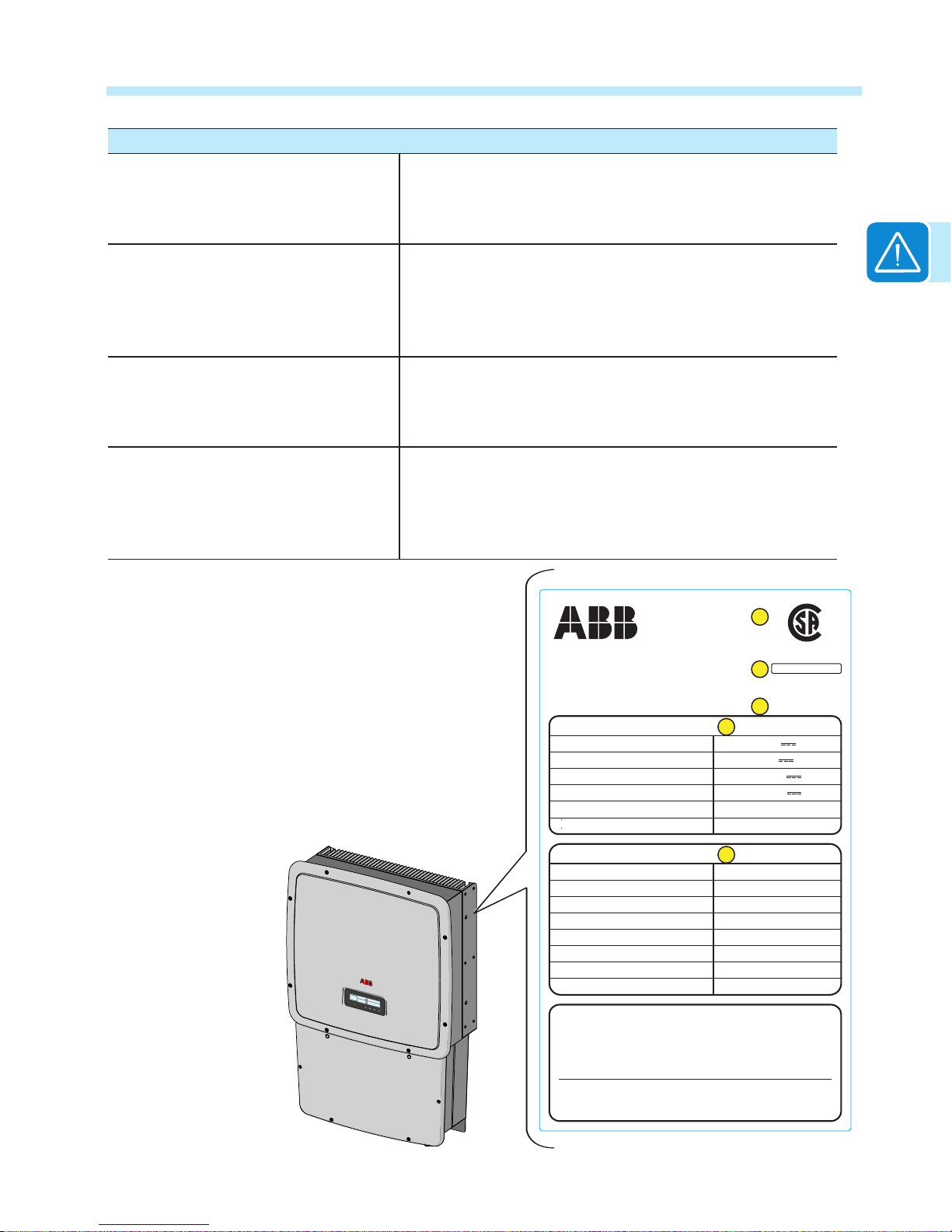
Regulatory label
Technical data in this manual does not
supersede the data on the labels afxed
to the equipment. The nameplate
shown is afxed to the inverter and
provides the following information:
1. Certication
2. Product origin
3. Model name
4. DC input data
5. AC output data
UL 1741
CSA-C22.2 No. 107.1-01
C US
®
Made in Italy
www.abb.com/solar
SOLAR GRID TIED INVERTER
UTILITY INTERACTIVE - TRANSFORMERLESS INVERTER
MODEL: TRIO-20.0-TL-OUTD-S-US-480-A
OperatingAmbient Temperature:-25 to +60°C (-13 to +140 °F),with OutputPower Derating
Type of Enclosure:NEMA 4X
Photovoltaic Arc-Fault Circuit Protection - Type 1
( ):
1
For More Details Refer to the Instructions Manual
( ):
2
For each of the two input channels
( ):
3
Adjustable from 57.0 Hz to 59.8 Hz
( ):
4
Adjustable from 60.2 Hz to 63.0 Hz
This device complies with Part 15 of the FCC Rules. Operation is subject to the
following two conditions: (1) this device may not cause harmful interference, and
(2) this device must accept any interference received, including interference that
may cause undesidered operation.
Nominal Input Operating Voltage
Max. Input Voltage
Range of Input Operating Voltage
Range of Input Voltage @Full Power
Max. Input Current
Max. Input Short Circuit Current (P.V. Panels
DC RATING
Nominal Output Voltage
Operating Voltage Range
Nominal Output Frequency
Operating Frequency Range
Output Power Factor
Max. Output Current
AC RATING
Max. Continuous Output Power
Max. Output Overcurrent Protection
25 A ( )( )
1 2
30 A ( )( )
1 2
700 V
1000 V ( )
1
200 - 950 V ( )
1
450 - 800 V ( )
1
60 Hz (factory preset)
59.3 ( ) - 60.5 Hz ( )
3 4
>0.995
27 A (rms)
480 V~ 3Ø
40 A (rms)
20000 W @ 45°C amb.
422-528 V~
1
2
3
4
5

T004CC1
- 16 -
1- Introduction and safety
This page is intentionally blank.

- 17 -
T005CH2
Transportation and handling
Transportation of the equipment, especially by road, must be carried out by suitable ways and means for protecting
the components (in particular, the electronic components) from violent shocks, humidity, vibration, etc. During
handling, do not make any sudden or fast movements that can create dangerous swinging.
NOTE: During transportation the crated TRIO inverters should only be stacked three high.
For storage purposes, units in their original unopened packaging can be stacked ve high on a at
dry surface capable of withstanding the weight.
DO NOT stack with equipment or products other than those indicated or store in damaging, corrosive
environments.
Lifting
ABB packages and protects individual components using suitable means to make their transport
and subsequent handling easier. Due to the weight and complexity of this equipment, ABB
recommends the process of loading and unloading of this equipment be done by an experienced
or specialized staff knowledgeable in material handling.
Where indicated or where there is a provision, eyebolts or handles can be inserted and used as
lifting points. Do not lift several units or parts of the equipment at the same time, unless otherwise
indicated.
Incoming inspection
It is the customer’s responsibility to examine the condition of the unit. Upon receipt of the inverter,
please check the following:
• Inspect the shipping container for any external damage.
• Inventory the contents against the table below and verify receipt of all items.
• Use care not to discard any equipment, parts, or manuals.
• Call the delivering carrier if damage or shortage is detected.
2
Installation location
T006CC2
- 18 -
2 - Installation
If inspection reveals damage to the inverter, contact the supplier or authorized distributor for a
repair/return determination and instructions regarding the process.
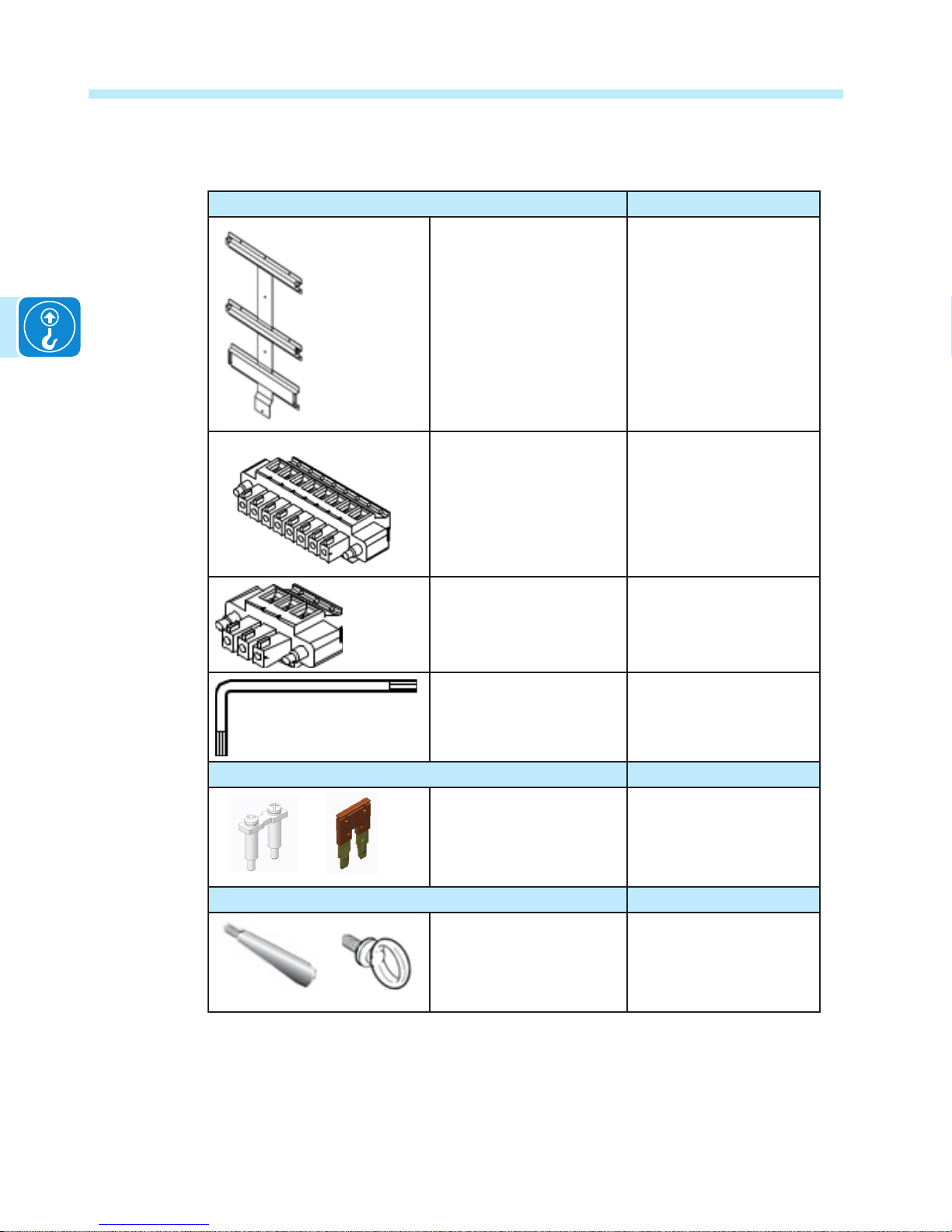
COMPONENTS FOR ALL MODELS QTY/PART NO.
(1) Mounting bracket,
(10 each) wall anchor,
screw, washer,
(1) locking screw for securing wiring box to mounting
bracket
Bracket
XAK.V0L03.0
OR
Mounting kit
XAK.V0L01.0
8 pin connector 4
82000005908-G
3 pin connector 2
82000005907-G
Torx wrench;
90°; T20; 64x23mm,
1
81510000077
COMPONENTS FOR NON-AFD MODELS ONLY QTY/PART NO
Jumpers for conguration
of parallel input channels
2 each
Reliance RAQ2-16,
ABB JB12-2
OPTIONAL COMPONENT QTY/PART NO
Optional lifting kit includes
handles and eyebolts for
lifting the inverter
1 kit M12
3M2200HNDK0

- 19 -
T006CC2
2 - Installation
Handling the TRIO
The TRIO inverter and wiring box are shipped as separate components within a common
container. They are designed to be installed individually allowing an easier installation process.
The inverter unit weighs 143 pounds or less, depending on the version, and should always be
lifted by two persons.
An optional lifting kit, with handles and eyebolts for lifting the inverter, is available and can be
used to assist in hanging the inverter on the mounting bracket.
T006CC2
- 20 -
2 - Installation
Select the installation location
WARNING!
The TRIO inverter must be installed by qualied installers and/or licensed electricians
according to the applicable local code regulations (NEC, CEC, and other).
Once physically mounted, the wiring must be carried out with the equipment disconnected from the
grid (power disconnect switch open) and the photovoltaic modules shaded or isolated.
Environmental check
• See technical data in the Appendix, section 7, to check the environmental parameters to be
observed (degree of protection, temperature, humidity, altitude, etc.).
• The maximum operational ambient air temperature MUST be considered when choosing the
inverter installation location.
• Installing the inverter where operating temperatures exceed the specications will result in
power derating. It is recommended the inverter be installed within the specied temperature
range.
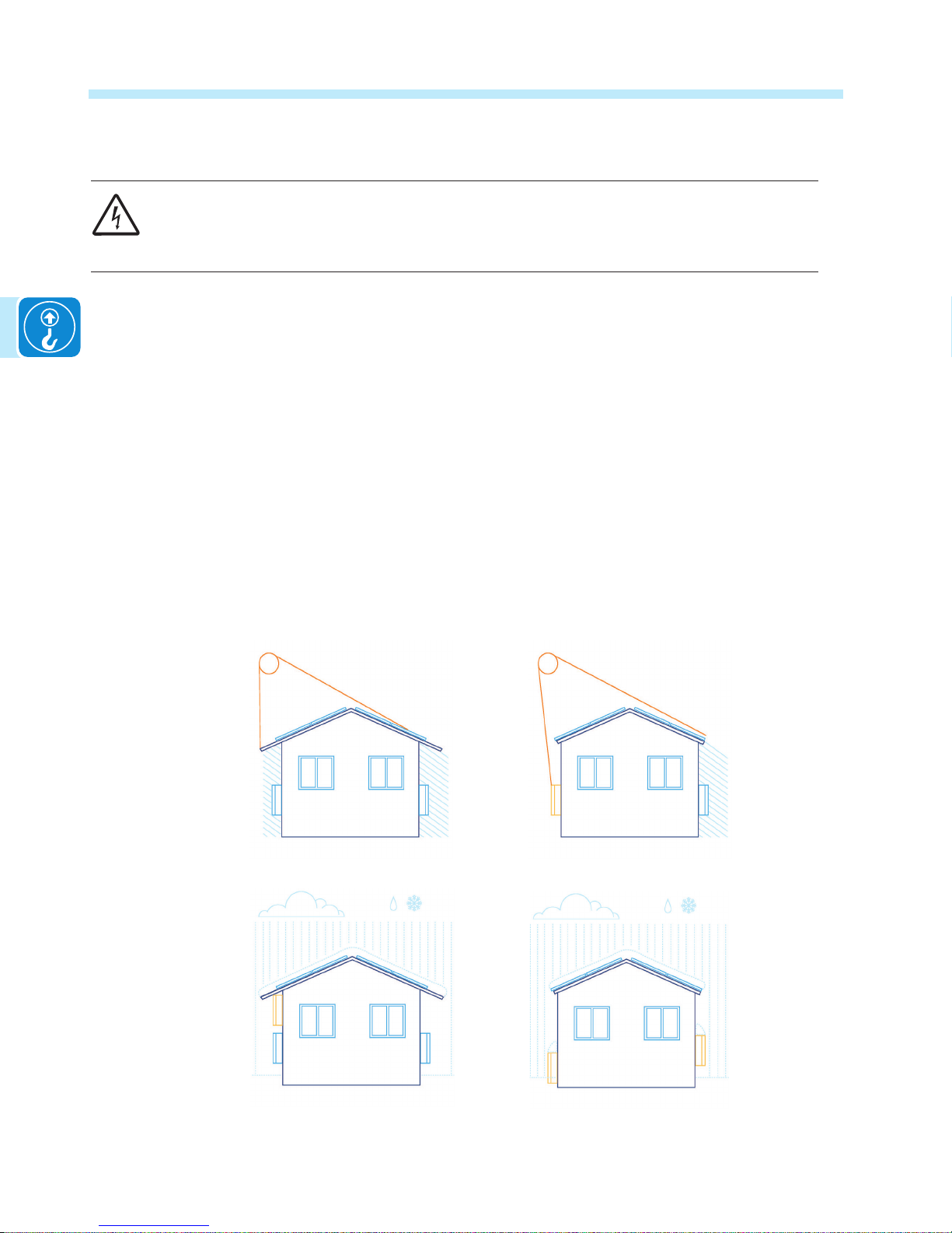
• Do not install in direct sunlight. If the preferred mounting location is in direct sunlight, install
the ABB Sun Shield on the inverter in order to provide the necessary shade.
• Do not install in small closed spaces where air cannot circulate freely.
• Due to acoustical noise (about 50dBA at 1 m) from the inverter, do not install in rooms where
people live or where the prolonged presence of people or animals is expected.
• To avoid overheating, always make sure the ow of air around the inverter is not blocked.
• Do not install in places where gases or ammable substances may be present.
Properly installed
Direct sun on left inverteruse ABB Sun Shade
Air restricted for top left
inverter - not properly installed
Air restricted by snow for both
inverters - not properly installed

- 21 -
T006CC2
2 - Installation
Installation position
When choosing the installation location and position, comply with the following conditions:
• Install on a wall or strong structure capable of bearing the weight.
• Install vertically with a maximum incline of +/- 5°. If the mounted inverter is tilted to an angle
greater than the maximum noted, heat dissipation can be inhibited, and may result in less
than expected output power.
• Install in a safe place where all switch handles and controls remain easy to reach and meet
height requirements of the applicable electrical code. Install at eye level so the display and
status LEDs can be easily seen.
• Ensure sufcient working area in front of the inverter to allow easy access and compliance
with the minimum clearance requirements of NEC 110.34(A).
• When planning the installation, maintain clearance distances shown to allow normal control
functions and easy maintenance operations.
32
in
20
in
6 in
6 in
UNO
T006CC2
- 22 -
2 - Installation
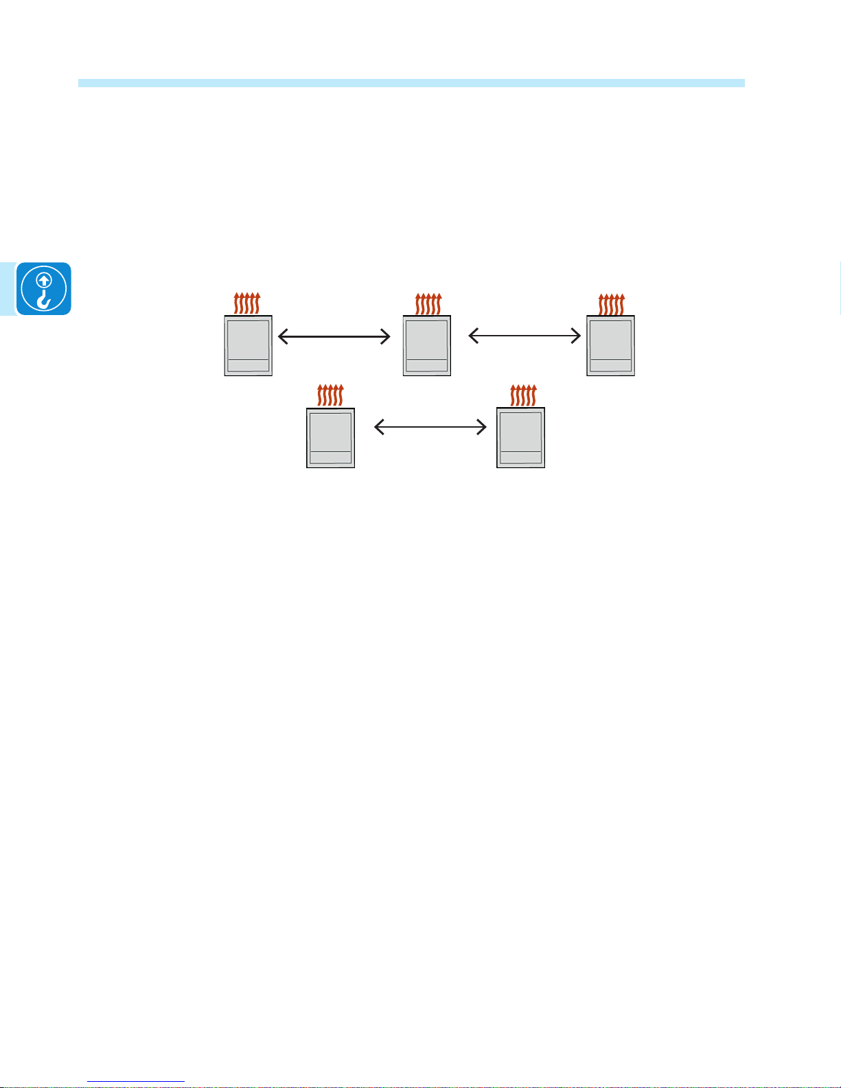
For multiple-inverter installations, position the inverters side-by-side, maintaining minimum
clearances. If the space available does not allow the side-by-side arrangement, multiple inverters
can be placed in the staggered arrangement shown; this minimizes heat dissipation from lower
inverters affecting operation of other inverters.
Minimum clearances illustrated include width of inverter plus additional allowances for inverters
arranged above or below.
Side-by-side arrangement
6”
6”
38”
38”
38”
- 23 -
T007CH3
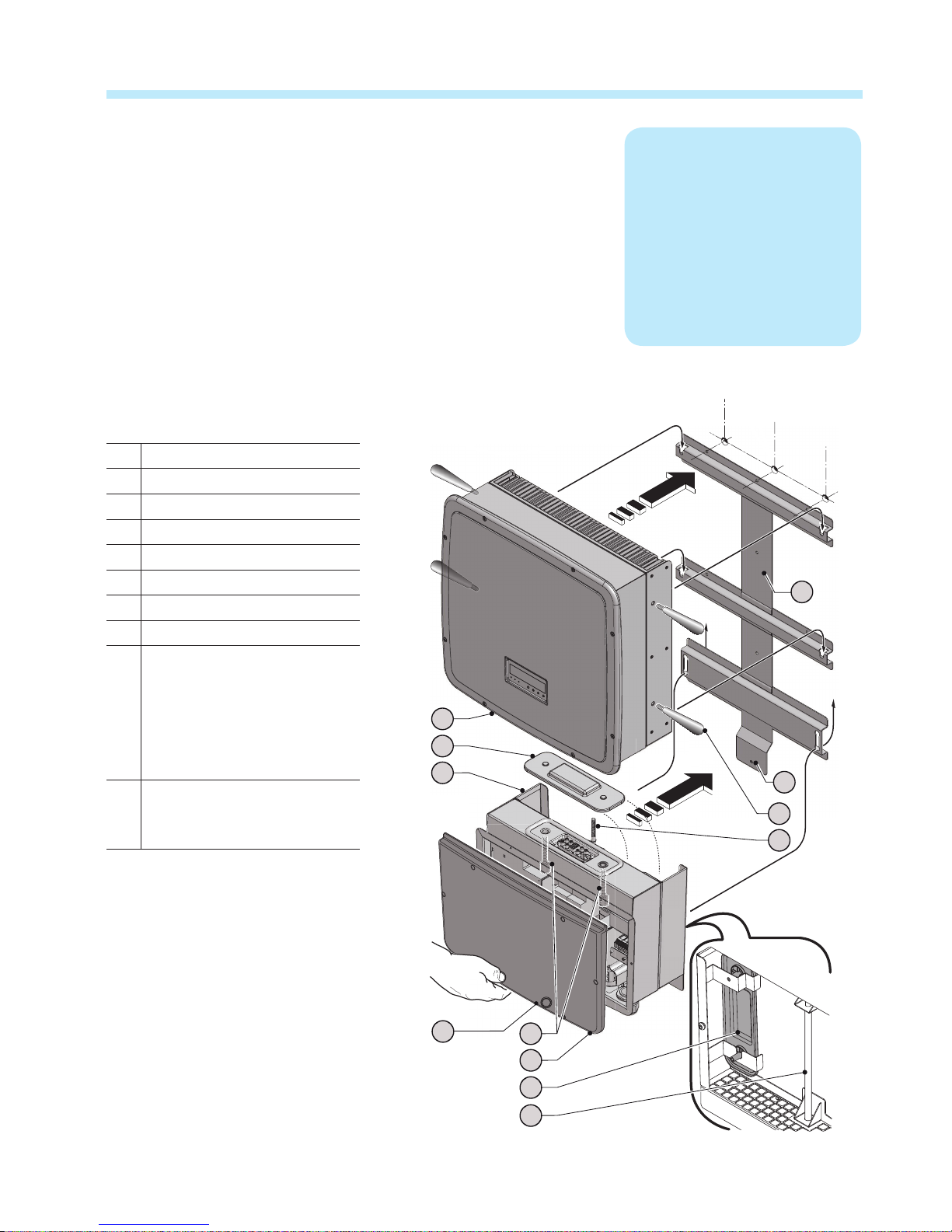
Labeled illustration of TRIO
01 mounting bracket
02 wiring box
03 inverter
04 coupling connector cover
05 clamp screw
06 optional handles
07 connector screws
08 wiring box cover
31 bottom locking tab for
securing mounting bracket
to wiring box and inverter,
can also be used as exterior
grounding electrode, if
required
32 hole on wiring box cover and
wiring box chassis used to
insert a padlock, if required
3
Mounting and wiring
31
06
05
03
04
08
04
05
02
07
01
32
T008CC3
- 24 -
3 - Mounting and wiring
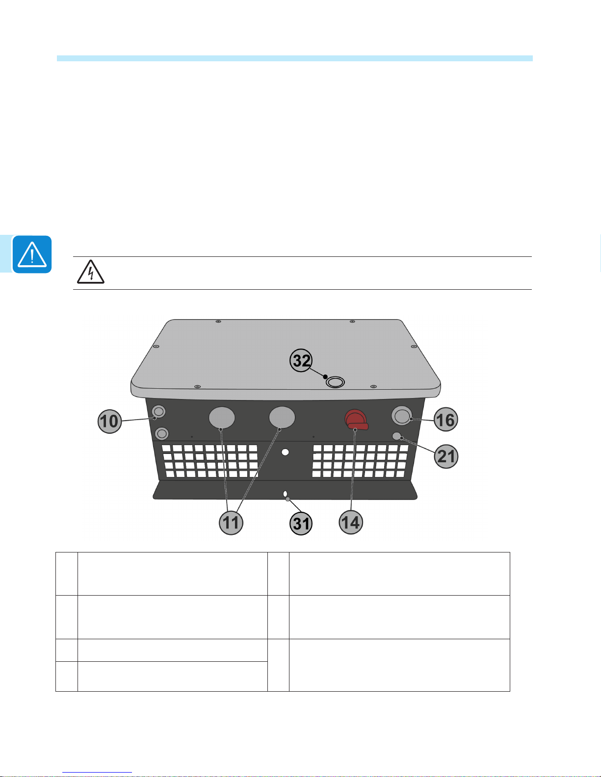
Conduit entries for all versions are located on the bottom of the wiring box along with the DC disconnect switch
handle 14. Conduit entries are illustrated below. The appropriate conduit connector must be used in order to
maintain required spacing between wiring groups and preserve the integrity of the NEMA 4X environmental rating.
• A silkscreen printed label on the wiring box front cover 08 illustrates the ON/OFF positioning of the disconnect
switch handle.
• In the OFF position (open and locked), the DC disconnect switch handle will be turned counter-clockwise in a
position parallel to the inverter mounting surface as illustrated below.
• In the ON position, the DC disconnect switch handle must be pushed in and turned clockwise to a position
perpendicular to the inverter mounting surface.
• The cover is only removable with the DC disconnect switch handle set to the OFF position.
• A padlock can be inserted in the slot on the switch handle when in the OFF position to prevent the disconnect
from being turned to the ON position.
WARNING! The DC switch (14) disconnects the photovoltaic array current from the inverter when
the switch is in OFF position. It DOES NOT disconnect the AC from the grid.
10 Service and communications cable open-
ing with plastic threaded plug, Trade size
1/2“
21 Anti-condensation valve (eliminates
condensation buildup) DO NOT REMOVE!
11 DC cable openings with plastic threaded
plug, Trade size 1”, 1 ½”
31 Bottom locking tab for securing mounting bracket
to inverter and wiring box, can also be used as
exterior grounding electrode terminal if required.
14 DC disconnect switch handle.
32 Hole on wiring box cover and wiring box chassis
used to insert a padlock,if required.
16 AC cable opening with plastic threaded
plug, Trade size 1”

T008CC3
- 25 -
3 - Mounting and wiring
Wall mounting
When mounting the TRIO, rst secure the mounting bracket to the desired location and then install
the wiring box followed by the inverter unit.
Included in the shipping package is a mounting kit with stainless steel screws and wall anchors for mounting the
powder coated, stainless steel bracket to a wall or structure The overall dimensions of the mounting bracket are
expressed in millimeters and inches.
991.91mm
39.05’’
0
18mm
0.7’’
164.36mm
6.47’’
382.63mm
15.06’’
554.9mm
21.84’’
730.41mm
28.75’’
978.9mm
38.54’’
0
101mm
3.97’’
301mm
11.85’’
0
21mm
0.82’’
501mm
19.72’’
581mm
22.87’’
25mm
0.98’’

T008CC3
- 26 -
3 - Mounting and wiring
The process of joining the inverter and wiring box together should be completed before the
conduit is secured. When completely tightened the wiring box will move up to meet the inverter.
It is recommended to employ exible conduit methods to allow for easy removal of the inverter, if
ever required.
Installation method with flexible conduit
When installing exible conduit with the TRIO, provide enough conduit to allow for approximately
1-1½” of vertical movement between the inverter and wiring box. Prior to making the conductor
connections in the wiring box, provide enough conductor to allow for the movement of the wiring
box in the nal stages.
01
A
A
A
A
A
A
A
A
A
A
10 x Ø 10 mm
• Using a level, position the bracket
01 level on the wall, using it as a
drilling template.
• Using a 10mm drill bit, drill the
required 10 holes A 70mm deep.
• Using the 10 (ten) 10mm diameter
wall anchors, screw the bracket to
the wall.
• When installing in seismic Zone
3 or higher, the ve center wall
anchors must be xed into a
wood/steel wall stud or concrete/
masonry wall.

T008CC3
- 27 -
3 - Mounting and wiring
01
04
04
05
09
02
08
07
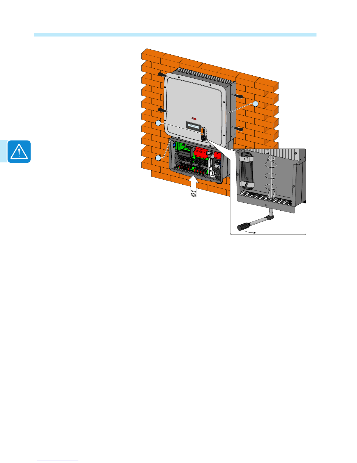
• Remove the front cover 08 from
the wiring box.
• Install the wiring box 02 onto the
bracket by inserting the heads of
the rear screws into the slots in
the bracket.
Note: it is not necessary to
install the inverter 03 at this
time.
• Unscrew the connector screws
07 and remove the wiring boxto-inverter cover 04 so that
the connector can be reached
between the wiring box and the
inverter.
• Put the wiring box-to-inverter
cover in the special pocket
provided at the back of the wiring
box.
• Locate the four bolts protruding
from the rear of the inverter
chassis; these are used as
mounting studs and are inserted
into the four associated slots on
the mounting bracket.
• Lift the inverter using two people
and orient it to the bracket so the
four studs are just above their
associated slots.
• Once aligned, lower the inverter
unit into position, ensuring all
four studs are seated in their
respective bracket slots.
• For ease of lifting, the optional
lifting kit is recommended (part #
3M2200HNDK0). The kit includes
both handles and eye bolts which
screw into the inverter heatsink.
POWER ALARM GFI ESC UP DOWN ENTER
TRIO
01
09
02
07
03
T008CC3
- 28 -
3 - Mounting and wiring
POWER ALARM GFI ESC UP DOWN ENTER
TRIO
05
02
03
• Join together the wiring box and
inverter by tightening the coupling
screw 05, working from the
underside of the wiring box.
• Using a 20mm socket, tighten the
clamp screw 05 to lift the inverter
wiring box toward the inverter until
mating connectors of the wiring
box and inverter chassis seat fully.
Do not completely tighten at
this time.
T008CC3
- 29 -
3 - Mounting and wiring
Installation method with rigid conduit
If installing rigid conduit with the TRIO, mount the inverter as instructed above before making the
rigid conduit connections. The inverter wiring box moves up in the installation procedure and the
connection of rigid conduit would prevent this necessary movement if installed prior to mounting
the inverter.
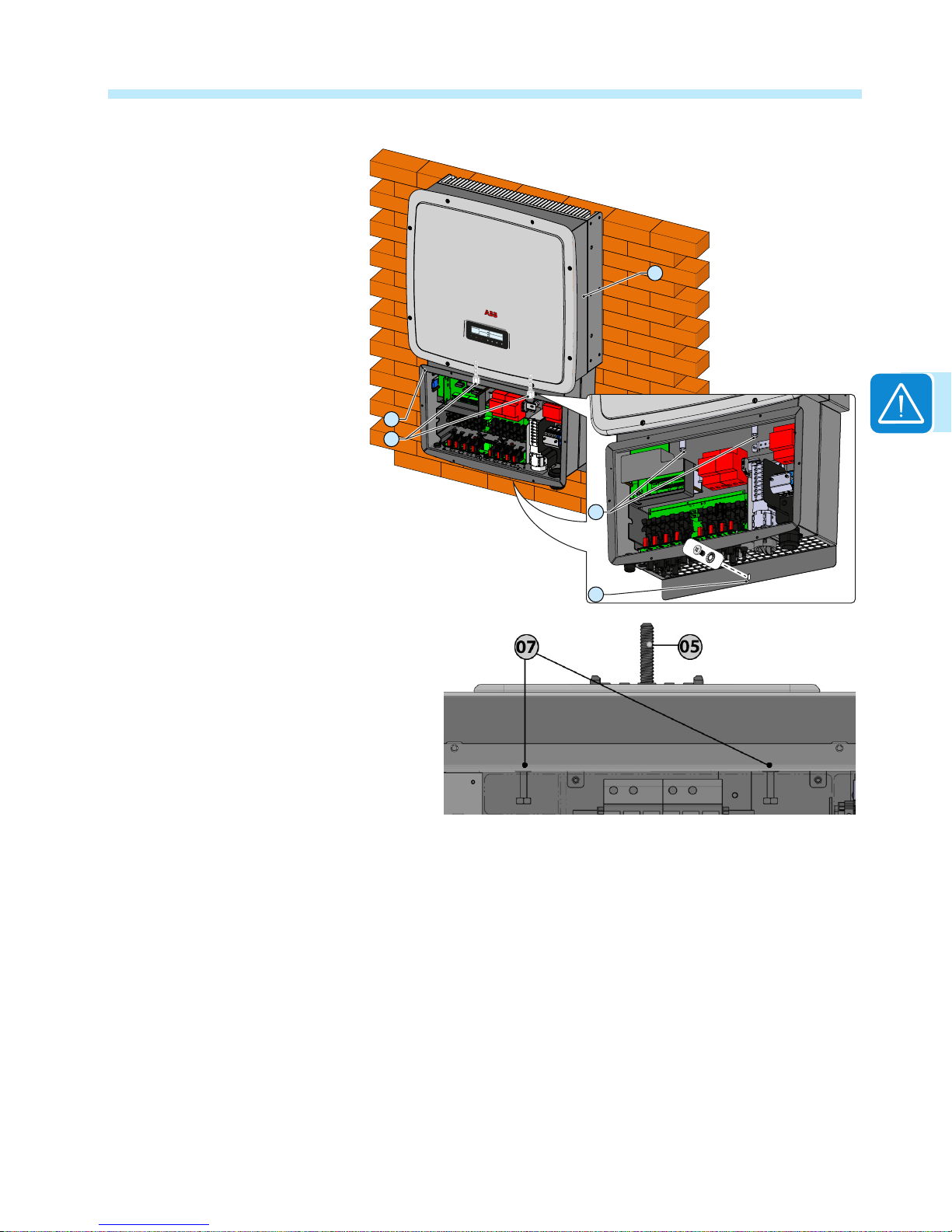
• Once the wiring box and inverter
are connected, screw in the two
connector screws 07 located
inside the wiring box to fully lock
and seal the connection.
• Using a 13mm socket wrench,
nish tightening each of the two
connector screws 07 to at least
13.3-14.75 ft-lbs (18-20Nm)
torque.
• After tightening the connector
screws 07, nish tightening the
clamp screw 05 at the bottom
of the wiring box to 13.3 ft-lbs
(18Nm) of torque.
• Anchor the connected wiring
box and inverter to the lower
end of the bracket by tightening
the locking screw 27 located
underneath the wiring box.
• Upon completion, replace the
front cover of the wiring box 08
and torque screws to at least 21
in-lbs (2Nm) to ensure proper
waterproof sealing.
POWER ALARM GFI ESC UP DOWN ENTER
TRIO
02
03
07
07
27
 Loading...