


 Loading...
YOKOGAWA DY015, DY025, DY040, DY050, DY080 User's Manual
...User’s |
Model DY |
|
|
|
|
|
|
|
|
|
|
|
|
|
|
|
|
|
|
|
|
|
|
||
Manual |
Vortex Flowmeter |
|||||||||||
|
(Integral Type, Remote Type) |
|||||||||||
|
Model DYA |
|||||||||||
|
Vortex Flow Converter |
|||||||||||
|
(Remote Type) |
|||||||||||
|
|
|
|
|
|
|
|
|
|
IM 1F6A0-01E |
||
|
|
|
|
|
|
|
|
|
|
|
|
|
|
|
|
|
|
|
|
|
|
|
|
|
|
|
|
|
|
|
|
|
|
|
|
|
|
|
|
|
|
|
|
|
|
|
|
|
|
|
|
|
|
|
|
|
|
|
|
|
|
|
|
|
IM 1F6A0-01E
8th Edition
Yokogawa Electric Corporation
|
|
|
|
CONTENTS |
|
|
|
CONTENTS |
|
INTRODUCTION .............................................................................................................................................. |
|
iv |
||
1. |
HANDLING PRECAUTIONS ................................................................................................................ |
1-1 |
||
|
1.1 |
Model and Specifications ........................................................................................................................... |
1-1 |
|
|
1.2 |
Precautions Regarding Transportation and Storage Location ............................................................... |
1-1 |
|
|
1.3 |
Precautions Regarding Installation Locations ........................................................................................ |
1-1 |
|
2. |
INSTALLATION .................................................................................................................................... |
2-1 |
||
|
2.1 |
Precautions Regarding Installation Locations ........................................................................................ |
2-1 |
|
|
2.2 |
Piping |
........................................................................................................................................................... |
2-1 |
|
2.3 |
Precautions Regarding Installation .......................................................................................................... |
2-4 |
|
|
2.4 |
Piping to Improve Durability ...................................................................................................................... |
2-5 |
|
|
2.5 |
Cryogenic and High process Temperature Version Insulation ............................................................... |
2-5 |
|
|
2.6 |
Installing the Vortex Flow-meter ................................................................................................................ |
2-6 |
|
3. |
WIRING ................................................................................................................................................. |
|
3-1 |
|
|
3.1 |
Wiring Precautions ..................................................................................................................................... |
3-1 |
|
|
3.2 |
Wiring for Output Condition ...................................................................................................................... |
3-1 |
|
|
3.3 |
Connection .................................................................................................................................................. |
3-2 |
|
|
3.4 |
Wiring Cables and Wires ............................................................................................................................ |
3-4 |
|
|
3.5 |
Connection of the Remote Type Signal Cable .......................................................................................... |
3-4 |
|
|
3.6 |
Method of Finishing the Signal Cable End(DYC) ..................................................................................... |
3-5 |
|
|
|
3.6.1 |
For Vortex Flowmeter (DY-N) ........................................................................................................................... |
3-5 |
|
|
3.6.2 |
For Vortex Flow Converter (DYA) .................................................................................................................... |
3-6 |
|
3.7 |
Wiring Cautions .......................................................................................................................................... |
3-7 |
|
|
3.8 |
Grounding ................................................................................................................................................... |
3-7 |
|
4. |
BASIC OPERATING PROCEDURES .................................................................................................. |
4-1 |
||
|
4.1 |
Construction of the Display ....................................................................................................................... |
4-1 |
|
|
4.2 |
Display Contents in Display Section ........................................................................................................ |
4-2 |
|
|
4.3 |
Display Contents in Display Section ........................................................................................................ |
4-3 |
|
|
|
4.3.1 |
Change the Display Mode from % Display to Engineering Unit ....................................................................... |
4-4 |
|
|
4.3.2 |
Indicate the Total Rate in the Lower Display ..................................................................................................... |
4-5 |
|
4.4 |
Setting Mode ............................................................................................................................................... |
4-6 |
|
|
|
4.4.1 |
Structure of Setting Mode Display ..................................................................................................................... |
4-6 |
|
|
4.4.2 |
Method of Parameter Setting .............................................................................................................................. |
4-7 |
|
4.5 |
Operation for the BT200 ............................................................................................................................. |
4-9 |
|
|
|
4.5.1 |
Connection Method for the BT200 .................................................................................................................... |
4-9 |
|
|
4.5.2 |
Displaying Flow Rate Data .............................................................................................................................. |
4-10 |
|
|
4.5.3 |
Setting Parameters ............................................................................................................................................ |
4-11 |
|
4.6 |
Operation for HART Communicator ........................................................................................................ |
4-13 |
|
|
|
4.6.1 |
Interconnection between digitalYEWFLO and HART Communicator ........................................................... |
4-13 |
|
|
4.6.2 |
Communication Line Requirements ................................................................................................................ |
4-14 |
|
|
4.6.3 |
Keys and Functions of Model 275 ................................................................................................................... |
4-15 |
|
|
4.6.4 |
Display ............................................................................................................................................................. |
4-16 |
|
|
4.6.5 |
Calling Up Menu Addresses ............................................................................................................................. |
4-17 |
|
|
4.6.6 |
Entering, Setting and Sending Data ................................................................................................................. |
4-18 |
|
|
4.6.7 |
Parameters Configuration ................................................................................................................................. |
4-18 |
|
|
4.6.8 |
Unique Functions of HART Communicator .................................................................................................... |
4-19 |
|
|
4.6.9 |
Data Renewing ................................................................................................................................................. |
4-19 |
|
|
4.6.10 |
Checking for Problems ..................................................................................................................................... |
4-19 |
|
|
4.6.11 |
Write Protect .................................................................................................................................................... |
4-20 |
IM 1F6A0-01E
8th Edition : Nov. 2005(KP)
All Rights Reserved, Copyright © 2001. Yokogawa Electric Corporation
i |
IM 1F6A0-01E |
|
|
|
|
CONTENTS |
|
|
4.6.12 |
Menu Tree ........................................................................................................................................................ |
4-21 |
5. |
PARAMETERS ..................................................................................................................................... |
5-1 |
||
|
5.1 |
Parameter Setup ......................................................................................................................................... |
5-1 |
|
|
5.2 |
Multi-Variable Type Parameter (Only for /MV) ........................................................................................... |
5-1 |
|
|
5.3 |
Parameters List ........................................................................................................................................... |
5-1 |
|
|
5.4 |
Parameter Description ............................................................................................................................... |
5-9 |
|
|
5.5 |
Error Code Lists ........................................................................................................................................ |
5-17 |
|
6. |
OPERATION ......................................................................................................................................... |
6-1 |
||
|
6.1 |
Adjustment .................................................................................................................................................. |
6-1 |
|
|
|
6.1.1 |
Zero Adjustment ................................................................................................................................................. |
6-1 |
|
|
6.1.2 |
Span Adjustment ................................................................................................................................................ |
6-1 |
|
|
6.1.3 |
Loop test ............................................................................................................................................................. |
6-1 |
|
|
6.1.4 |
Totalizer Function Start and Totalized Value Reset ............................................................................................ |
6-1 |
|
|
6.1.5 |
Unit of Pulse Output (Scaling) ........................................................................................................................... |
6-2 |
|
|
6.1.6 |
Power Failure ..................................................................................................................................................... |
6-2 |
|
6.2 |
Adjustment for Manual Mode .................................................................................................................... |
6-2 |
|
|
|
6.2.1 |
Low Cut Adjustment .......................................................................................................................................... |
6-2 |
|
|
6.2.2 |
Tuning ................................................................................................................................................................ |
6-2 |
|
6.3 |
Other Maintenance ..................................................................................................................................... |
6-3 |
|
|
|
6.3.1 |
Cleaning Precautions .......................................................................................................................................... |
6-3 |
7. |
MAINTENANCE ................................................................................................................................... |
7-1 |
||
|
7.1 |
Changing the Terminal Box Orientation ................................................................................................... |
7-2 |
|
|
7.2 |
Indicator Removal and Rotation ................................................................................................................ |
7-3 |
|
|
7.3 |
Amplifier Unit Removal .............................................................................................................................. |
7-3 |
|
|
7.4 |
Amplifier Unit Assembling ......................................................................................................................... |
7-3 |
|
|
7.5 |
Vortex Shedder Removal ............................................................................................................................ |
7-4 |
|
|
7.6 |
Setting Switches ......................................................................................................................................... |
7-6 |
|
|
|
7.6.1 |
Setting of Burnout Switch .................................................................................................................................. |
7-6 |
|
|
7.6.2 |
Setting of Write Protect Switch .......................................................................................................................... |
7-6 |
|
7.7 |
Software Configuration .............................................................................................................................. |
7-7 |
|
8. |
TROUBLESHOOTING .......................................................................................................................... |
8-1 |
||
|
8.1 |
Flow .............................................................................................................................................................. |
|
8-1 |
|
8.2 |
Flow (Only for /MV) ..................................................................................................................................... |
8-4 |
|
9. |
GENERAL DESCRIPTION ................................................................................................................... |
9-1 |
||
|
9.1 |
Outline ......................................................................................................................................................... |
9-1 |
|
|
9.2 |
Standard Specifications ............................................................................................................................. |
9-2 |
|
|
9.3 |
Model and Suffix Codes ............................................................................................................................. |
9-5 |
|
|
9.4 |
Option Specifications ................................................................................................................................. |
9-7 |
|
|
|
9.4.1 |
Option Specifications ......................................................................................................................................... |
9-7 |
|
|
9.4.2 |
Option Multi-Variable (Build in Temperature Sensor) Type (/MV)(*1) ............................................................ |
9-9 |
|
|
9.4.3 |
Option Specifications (Hazardous Area Classifications) ................................................................................. |
9-11 |
|
9.5 |
Sizing |
......................................................................................................................................................... |
9-14 |
|
9.6 |
External Dimensions ................................................................................................................................ |
9-18 |
|
10. |
EXPLOSION PROTECTED TYPE INSTRUMENT ............................................................................. |
10-1 |
||
|
10.1 |
CENELEC ATEX (KEMA) .......................................................................................................................... |
10-1 |
|
|
|
10.1.1 |
Technical Data .................................................................................................................................................. |
10-1 |
|
|
10.1.2 |
Installation ........................................................................................................................................................ |
10-2 |
|
|
10.1.3 |
Operation .......................................................................................................................................................... |
10-2 |
|
|
10.1.4 |
Maintenance and Repair ................................................................................................................................... |
10-2 |
|
|
10.1.5 |
Installation Diagram of Intrinsically safe (and Note) ...................................................................................... |
10-3 |
|
|
10.1.6 |
Installation Diagram of Type of Protection “n” ............................................................................................... |
10-3 |
ii |
IM 1F6A0-01E |
|
|
|
CONTENTS |
|
10.1.7 |
Data Plate ......................................................................................................................................................... |
10-4 |
|
10.1.8 |
Screw Marking ................................................................................................................................................. |
10-4 |
10.2 |
FM ............................................................................................................................................................... |
|
10-5 |
|
10.2.1 |
Technical Data .................................................................................................................................................. |
10-5 |
|
10.2.2 |
Wiring ............................................................................................................................................................... |
10-5 |
|
10.2.3 |
Operation .......................................................................................................................................................... |
10-5 |
|
10.2.4 |
Maintenance and Repair ................................................................................................................................... |
10-5 |
|
10.2.5 |
Installation Diagram ......................................................................................................................................... |
10-6 |
|
10.2.6 |
Data Plate ......................................................................................................................................................... |
10-7 |
10.3 |
SAA ............................................................................................................................................................ |
|
10-7 |
|
10.3.1 |
Technical Data .................................................................................................................................................. |
10-7 |
|
10.3.2 |
Installation ........................................................................................................................................................ |
10-8 |
|
10.3.3 |
Operation .......................................................................................................................................................... |
10-8 |
|
10.3.4 |
Maintenance and Repair ................................................................................................................................... |
10-8 |
|
10.3.5 |
Installation Diagram ......................................................................................................................................... |
10-8 |
|
10.3.6 |
Data Plate ......................................................................................................................................................... |
10-9 |
10.4 |
CSA .......................................................................................................................................................... |
|
10-10 |
|
10.4.1 |
Technical Data ................................................................................................................................................ |
10-10 |
|
10.4.2 |
Wiring ............................................................................................................................................................. |
10-11 |
|
10.4.3 |
Operation ........................................................................................................................................................ |
10-11 |
|
10.4.4 |
Maintenance and Repair ................................................................................................................................. |
10-11 |
|
10.4.5 Installation Diagram Intrinsically Safe (and Note) ........................................................................................ |
10-11 |
|
|
10.4.6 |
Data Plate ....................................................................................................................................................... |
10-12 |
10.5 |
TIIS ........................................................................................................................................................... |
|
10-13 |
11. PRESSURE EQUIPMENT DIRECTIVE .............................................................................................. |
11-1 |
||
INSTALLATION AND OPERATING PRECAUTIONS FOR JIS FLAMEPROOF EQUIPMENT ................. |
EX-1 |
||
REVISION RECORD
iii |
IM 1F6A0-01E |

INTRODUCTION
INTRODUCTION
The DY series of vortex flowmeters have been fine-tuned to your order specifications prior to shipment. Before use, read this manual thoroughly and familiarize yourself fully with the features, operations and handling of digitalYEWFLO to have the instrument deliver its full capabilities and to ensure its efficient and correct use.
■Notices Regarding This Manual
•This manual should be passed to the end user.
•The contents of this manual are subject to change without prior notice.
•All rights reserved. No part of this document may be reproduced or transmitted in any form or by any means without the written permission of Yokogawa Electric Corporation (hereinafter simply referred to as Yokogawa).
•This manual neither does warrant the marketability of this instrument nor it does warrant that the instrument will suit a particular purpose of the user.
•Every effort has been made to ensure accuracy in the contents of this manual. However, should any questions arise or errors come to your attention, please contact your nearest Yokogawa sales office that appears on the back of this manual or the sales representative from which you purchased the product.
•This manual is not intended for models with custom specifications.
•Revisions may not always be made in this manual in conjunction with changes in specifications, constructions and/or components if such changes are not deemed to interfere with the instrument’s functionality or performance.
■Notices Regarding Safety and Modification
•For the protection and safety of personnel, the instrument and the system comprising the instrument, be sure to follow the instructions on safety described in this manual when handling the product. If you handle the instrument in a manner contrary to these instructions, Yokogawa does not guarantee safety.
•If this instrument is used in a manner not specified in this manual, the protection provided by this instrument may be impaired.
•As for explosionproof model, if you yourself repair or modify the instrument and then fail to return it to its original form, the explosion-protected construction of the instrument will be impaired, creating a hazardous condition. Be sure to consult Yokogawa for repairs and modifications.
Safety and Modification Precautions
•The following general safety precautions must be observed during all phases of operation, service, and repair of this instrument. Failure to comply with these precautions or with specific WARNINGS given elsewhere in this manual violates safety standards of design, manufacture, and intended use of the instrument. Yokogawa assumes no liability for the customer's failure to comply with these requirements. If this instrument is used in a manner not specified in this manual, the protection provided by this instrument may be impaired.
•The following safety symbol marks are used in this user's manual and instrument.
WARNING
A WARNING sign denotes a hazard. It calls attention to procedure, practice, condition or the like, which, if not correctly performed or adhered to, could result in injury or death of personnel.
CAUTION
A CAUTION sign denotes a hazard. It calls attention to procedure, practice, condition or the like, which, if not correctly performed or adhered to, could result in damage to or destruction of part or all of the product.
IMPORTANT
An IMPORTANT sign denotes that attention is required to avoid damage to the instrument or system failure.
NOTE
A NOTE sign denotes information necessary for essential understanding of operation and features.
Functional grounding terminal
Direct current
iv |
IM 1F6A0-01E |
INTRODUCTION
Warranty
•The warranty of this instrument shall cover the period noted on the quotation presented to the Purchaser at the time of purchase. The Seller shall repair the instrument free of charge when the failure occurred during the warranty period.
•All inquiries on instrument failure should be directed to the Seller’s sales representative from whom you purchased the instrument or your nearest sales office of the Seller.
•Should the instrument fail, contact the Seller specifying the model and instrument number of the product in question. Be specific in describing details on the failure and the process in which the failure occurred. It will be helpful if schematic diagrams and/or records of data are attached to the failed instrument.
•Whether or not the failed instrument should be repaired free of charge shall be left solely to the discretion of the Seller as a result of an inspection by the Seller.
■The Purchaser shall not be entitled to receive repair services from the Seller free of charge, even during the warranty period, if the malfunction or damage is due to:
•improper and/or inadequate maintenance of the instrument in question by the Purchaser.
•handling, use or storage of the instrument in question beyond the design and/or specifications requirements.
•use of the instrument in question in a location not conforming to the conditions specified in the Seller's General Specification or Instruction Manual.
•retrofitting and/or repair by an other party than the Seller or a party to whom the Seller has entrusted repair services.
•improper relocation of the instrument in question after delivery.
•reason of force measure such as fires, earthquakes, storms/ floods, thunder/lightning, or other reasons not attributable to the instrument in question.
v |
IM 1F6A0-01E |

■ Using the Vortex Flowmeter Safely
WARNING
(1) Installation
•Installation of the vortex flowmeter must be performed by expert engineer or skilled personnel. No operator shall be permitted to perform procedures relating to installation.
•The vortex flowmeter is a heavy instrument. Be careful that no damage is caused to personnel through accidentally dropping it, or by exerting excessive force on the vortex flowme-
ter. When moving the vortex flowmeter, always use a trolley and have at least two people carry it.
•When the vortex flowmeter is processing hot fluids, the instrument itself may become extremely hot. Take sufficient care not to get burnt.
•Where the fluid being processed is a toxic substance, avoid contact with the fluid and avoid inhaling any residual gas, even after the instrument has been taken off the line for maintenance and so forth.
•All procedures relating to installation must comply with the electrical code of the country where it is used.
(2) Wiring
•The wiring of the vortex flowmeter must be performed by expert engineer or skilled personnel. No operator shall be permitted to perform procedures relating to wiring.
•When connecting the wiring, check that the supply voltage is within the range of the voltage specified for this instrument before connecting the power cable. In addition, check that no voltage is applied to the power cable before connecting the wiring.
•The functional grounding must be connected
securely at the terminal with the  mark to avoid danger to personnel.
(3) Operation
•Only expert engineer or skilled personnel are permitted to open the cover.
(4) Maintenance
•Maintenance on the vortex flowmeter should be performed by expert engineer or skilled personnel. No operator shall be permitted to perform any operations relating to maintenance.
•Always conform to maintenance procedures outlined in this manual. If necessary, contact Yokogawa.
INTRODUCTION
•Care should be taken to prevent the build up of dirt, dust or other substances on the display panel glass or data plate. If these surfaces do get dirty, wipe them clean with a soft dry cloth.
(5) Explosion Protected Type Instrument
•For explosion proof type instrument, the description in Chapter 10 “EXPLOSION PROTECTED TYPE INSTRUMENT” is prior to the other description in this user's manual.
•Only trained persons use this instrument in the industrial location.
•The functional grounding  must be connected to a suitable IS grounding system.
•Take care not to generate mechanical spark when access to the instrument and peripheral devices in hazardous locations.
(6)European Pressure Equipment Directive (PED)
•When using the instrument as a PED-compliant product, be sure to read Chapter 11 before use.
vi |
IM 1F6A0-01E |

1. HANDLING PRECAUTIONS
1. HANDLING PRECAUTIONS
The Model DY Vortex Flowmeter and Model DYA Vortex Flow Converter are thoroughly tested at the factory before shipment. When these instruments are delivered, perform a visual check to ascertain that no damage occurred during shipment.
This section describes important cautions in handling these instruments. Read carefully before using them.
If you have any problems or questions, contact your nearest YOKOGAWA service center or sales representative.
1.1 Model and Specifications
The model and important specifications are indicated on the data plate attached to the case. Verify that they are the same as those specified in the original order, referring to paragraph 9.2 to 9.5. In any correspondence, always give model (MODEL), serial number (NO) and calibrated range (RANGE) from the data plate.
4 ~ 20mA DC / PULSE |
TAG NO. |
MPa at 38°C |
|
*1) |
|
10.5 ~ 42V DC |
3UA |
*2) |
|
*1): |
K factor at 15°C |
|
*2): |
The product - producing country. |
F010101.EPS |
Figure 1.1(a) Example of Data Plate for Integral Type
MPa at 38°C |
TAG NO. |
|
|
|
3WA |
4 ~ 20mA DC / PULSE |
TAG NO. |
10.5 ~ 42V DC |
3YA |
1.2Precautions Regarding Transportation and Storage Location
To protect against accidental damage to digitalYEWFLO while transporting it to a new location, pack it in the original
packing as when shipped from the Yokogawa factory.
WARNING
The Vortex Flowmeter is a heavy instrument. Please be careful to prevent persons from injuring when it is handled.
Deterioration in insulation or corrosion can occur for unexpected reasons if digitalYEWFLO is left uninstalled for a prolonged period after delivery. If digitalYEWFLO is likely to be stored over a prolonged period, observe the following precautions.
■Store the vortex flowmeter with forwarded statement.
■Choose a storage location that satisfies the following requirements:
•Not exposed to rain or splashwater.
•Less susceptible to mechanical vibration or shock.
•Kept within the temperature and humidity ranges shown
in the following table, preferably at normal temperature and humidity (approximately 25°C, 65%)
Temperature |
–40°C to +80°C |
|
|
Humidity |
5 to 100% (no condensation) |
|
|
T010201.EPS
1.3Precautions Regarding Installation Locations
(1) Ambient Temperature
Avoid an area which has wide temperature variations. When the installation area is subjected to heat radiation from process plant, ensure adequate heat prevention or ventilation.
(2) Atmospheric Conditions
Avoid installing the vortex flowmeter in a corrosive atmosphere. When the vortex flowmeter must be installed in a corrosive atmosphere, adequate ventilation must be provided.
F010102.EPS
Figure 1.1(b) Example of Data Plate for Remote Type
1-1 |
IM 1F6A0-01E |
1. HANDLING PRECAUTIONS
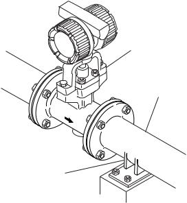
(3) Mechanical Shock or Vibration
The vortex flowmeter is of sturdy construction, but select an area subject to minimize mechanical vibrations or impact shock. If the flowmeter is subject to vibrations, it is recommended that pipeline supports to be provided as shown in Figure 1.2.
(4) Other Considerations
•Choose a location where is sufficient clearance around digitalYEWFLO exist to allow such work as routine inspections.
•Choose a location that ensures easy wiring and piping.
digitalYEWFLO Vortex Flowmeter
Pipeline
Pipeline Support
F010301.EPS
Figure 1.2
1-2 |
IM 1F6A0-01E |
2. INSTALLATION
2. INSTALLATION
WARNING
This instrument must be installed by expert engineer or skilled personnel. The procedures described in this chapter are not permitted for operators.
2.1Precautions Regarding Installation Locations
(1) Ambient Temperature
Avoid an area which has wide temperature variations. When the installation area is subjected to heat radiation from process plant, ensure adequate heat prevention or ventilation.
(2) Atmospheric Conditions
(4) Precautions Regarding Piping
(a)Ensure that the process connector bolts are tightened firmly.
(b)Ensure that no leak exists in the process connection pipeline.
(c)Do not apply a pressure higher than the specified maximum working pressure.
(d)Do not loosen or tighten the flange mounting bolts when the assembly is pressurized.
(e)Handle the vortex flowmeter carefully when measuring dangerous liquids, so that the liquids do not splash into eyes or on face. When using dangerous gases, be careful not to inhale them.
2.2 Piping
See Table 2.1 about Valve Position and Straight Pipe Length and so on.
Avoid installing the vortex flowmeter in a corrosive atmosphere. When the vortex flowmeter must be installed in a corrosive atmosphere, adequate ventilation must be provided
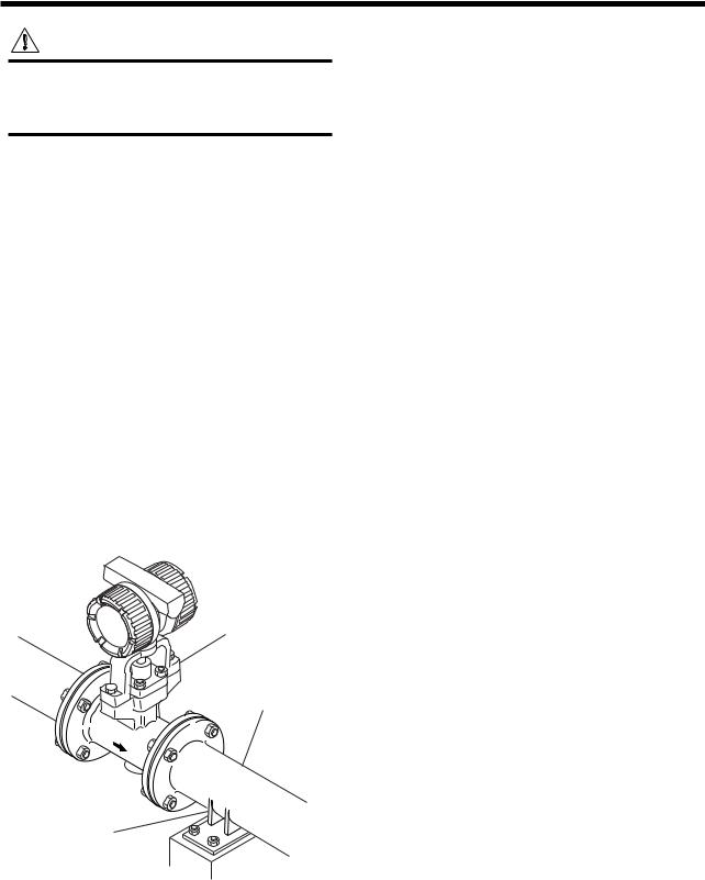
(3) Mechanical Shock or Vibration
The vortex flowmeter is of sturdy construction, but select an area subject to minimize mechanical vibration or impact shock. If the flowmeter is subject to vibrations, it is recommended that pipeline supports to be provided as shown in Figure 2.1.
digitalYEWFLO Vortex Flowmeter
Pipeline
Pipeline Support
F020101.EPS
Figure 2.1
2-1 |
IM 1F6A0-01E |
2. INSTALLATION
Table 2.1 Installation
Description |
Figure |
Piping support:
Typical vibration immunity level is 1G for normal piping condition.
Piping support shoud be fixed in case of over 1G vibration level.
Installation direction:
If a pipe is always filled with liquids, the pipe can be installed vertically or at inclined angle.
Adjacent pipes:
The process pipline inner diameter should be larger than the digitalYEWFLO inner diameter.
Use the following adjacent pipe.
Norminal size 15mm up to 50mm : Sch 40 or less. Norminal size 80mm up to 300mm : Sch 80 or less.
Reducer pipe: |
|
|
|
|
|
|
|
|
digitalYEWFLO |
|
|
||||||||
|
|
|
|
|
|
|
Flow |
|
|
||||||||||
Ensure the upstream straight pipe length to be 5D or more, and the |
|
|
|
|
|
|
|
|
|
||||||||||
|
|
|
|
|
|
|
|
|
|
|
|
|
|
|
|
|
|
|
|
downstream straight pipe length to be 5D or more for per reducer |
|
|
|
|
|
|
|
|
|
|
|
|
|
|
|
|
|
|
|
pipe. |
|
|
|
|
|
|
|
|
|
|
|
|
|
|
|
|
|
|
|
(D: digitalYEWFLO nominal diameter) |
Reducer |
|
|
|
|
|
|
5D or more |
|
|
|
|
|
|
|
||||
|
|
|
|
|
|
|
|
|
|
|
|
|
|
|
|
|
|
|
|
|
|
|
|
|
|
|
|
|
|
|
|
5D or more |
|
|
|||||
Expander pipe: |
|
|
|
|
|
|
|
|
digitalYEWFLO |
|
|
||||||||
Ensure the upstream straight pipe length to be 10D or more, and |
|
|
|
|
|
|
|
Flow |
|
|
|||||||||
the downstream straight pipe length to be 5D or more for per |
|
|
|
|
|
|
|
|
|
|
|
|
|
|
|
|
|
|
|
|
|
|
|
|
|
|
|
|
|
|
|
|
|
|
|
|
|
|
|
expander pipe. |
|
|
|
|
|
|
|
|
|
|
|
|
|
|
|
|
|
|
|
|
Expander |
|
|
|
|
|
|
10D or more |
|
|
|
|
|
|
|
||||
|
|
|
|
|
|
|
|
|
|
|
|
|
|
|
|
|
|
|
|
|
|
|
|
|
|
|
|
|
|
|
|
5D or more |
|
|
|||||
Bent pipe and straight pipe length: |
|
|
|
|
|
digitalYEWFLO |
|||||||||||
Ensure the upstream straight pipe length to be 10D or more, and |
|
|
|
|
|
|
|
|
Flow |
|
|
|
|
|
|||
the downstream straight pipe length to be 5D or more for per bent |
|
|
|
|
|
|
|
|
|
|
|
|
|
|
|
|
|
|
|
|
|
|
|
|
|
|
|
|
|
|
|
|
|
|
|
pipe. |
|
|
|
|
|
|
|
|
|
|
|
|
|
||||
|
|
|
|
|
|
|
|
|
|
|
|
|
|
|
|
||
|
|
|
|
|
|
|
10DxN or more |
|
|
|
5D or more |
||||||
|
|
|
|
|
|
|
|
|
|
||||||||
|
|
|
|
|
|
|
|
|
|
|
|
|
|
|
|
|
|
|
|
|
|
|
|
|
N: Number of bent pipe |
|
|
|
|
|
|||||
|
|
|
|
|
|
|
|
|
|
|
|
|
|
|
|
|
|
|
|
|
|
|
|
|
|
|
|
|
|
|
|
|
|
|
|
Valve position and straight pipe length: |
|
|
|
|
digitalYEWFLO |
|
|
|
|
|
|||||||
|
|
|
|
|
|
|
|
|
|
|
|
|
|||||
■Install the valve on the downstream side of the flowmeter. The upstream straight pipe length dependent on the element
Refer to each element above for
located on the upstream such as reducer/expander, bent and straight pipe run. etc., refer to description as above. Keep 5D or more for
downstream straight pipe length.
Flow |
Valve |
digitalYEWFLO |
|
■ In case the valve has to be installed on the upstream of the |
|
|
|
flowmeter, ensure the upstream straight pipe length to be 20D |
|
|
|
or more, and the downstream straight pipe length be 5D or more. |
|
|
|
|
|
|
|
|
|
20D or more |
5D or more |
|
|
|
|
|
|
|
digitalYEWFLO |
Fluid vibration:
For a gas line which uses a position-type or roots-type blower compressor or a high-pressure liquid line (about 1MPa or more) which uses piston-type or plunger-type pump, fluid vibrations may be produced.
In this case, install valve on the upstream side of digitalYEWFLO.
For inevitable fluid vibration, put a vibration damping device such as
throttling plate or expansion section in the upstream side of digitalYEWFLO digitalYEWFLO.
Piston-type or plunger pump: |
|
Install the accumulator on the upstream side of digitalYEWFLO to |
digitalYEWFLO |
reduce fluid vibrations. |
|
F020102-1.EPS
2-2 |
IM 1F6A0-01E |

2. INSTALLATION
Description |
|
|
|
|
|
|
|
Figure |
|
|
|
|
|
|
|
|
|
|
|
|
||||||||||
Valve positon (T-type piping exist): |
|
|
|
|
|
|
|
|
|
|
|
|
|
|
|
|
|
|
|
|
|
|
|
|
|
|
|
|
|
|
When pulsation causes by a T-type piping exist, install the valve |
|
|
|
|
|
|
|
|
|
|
|
|
|
|
|
|
|
|
|
|
|
|
|
|
|
|
|
|
|
|
|
|
|
|
|
|
|
|
|
|
|
|
|
|
|
|
|
|
|
|
|
|
|
|
|
|
|
|
|
|
|
on the upstream of the flowmeter. |
|
|
|
|
|
Relocating |
|
|
|
|
|
|
|
|
|
|
|
|
||||||||||||
Example:As shown in the figure, when the valve V1 is turned |
|
|
|
|
|
|
|
digitalYEWFLO |
|
|
Valve (Off) |
|||||||||||||||||||
Flow |
|
|
|
|
|
|
|
|
|
|
|
|
|
|
|
|
||||||||||||||
off, the fluid flow throught B as to meter A the flow is zero. But |
|
|
|
|
|
|
|
|
|
|
|
|
|
|
|
|||||||||||||||
|
|
|
|
|
|
|
|
|
|
|
|
|
|
|
|
|
|
|
|
|
|
|
|
|
|
|
|
|
|
|
due to the pulsating pressure is detected, the meter is zero |
B |
|
|
|
|
|
|
|
|
|
|
|
|
|
|
|
|
|
|
|
|
|
|
|
|
|
|
|
|
|
point become fluctuating. To avoid this, change the valve V1 |
|
|
|
|
|
|
|
|
|
|
|
|
|
|
|
|
|
|
|
|
|
|
|
|
|
|
|
|
|
|
|
|
|
|
|
|
|
|
|
|
|
|
|
|
|
|
|
|
|
|
|
|
|
|
|
|
|
|
|
||
location to V1'. |
|
|
|
|
|
V1’ |
|
|
|
|
|
|
|
|
|
|
V1 |
|||||||||||||
|
|
|
|
|
|
|
|
|
|
|
|
|
|
|
||||||||||||||||
|
|
|
|
|
|
|
|
|
|
|
|
|||||||||||||||||||
|
|
|
|
|
|
|
|
|
|
|
|
|
|
|
|
|
|
|
|
|
|
|
|
|
|
|
|
|
|
|
|
|
|
|
|
|
|
|
|
|
|
|
A |
|
|
|
|
|
|
|
|
|
|
|
|
||||||
|
|
|
|
|
|
|
|
|
|
|
|
|
|
|
|
|
|
|
|
|
|
|
|
|
|
|
|
|
|
|
|
|
|
|
|
|
|
|
|
|
|
|
|
|
|
|
|
|
|
|
|
|
|
|
|
|
|
|
|
|
|
Pressure and Temperature Taps: |
|
|
|
|
|
|
|
|
|
|
|
|
|
|
|
|
|
|
|
|
|
|
|
|
|
|
|
|
|
|
|
|
|
|
|
|
|
|
|
|
Pressure tap |
|
|
|
|
|
|
|
|
|
|
|
|
||||||||
Pressure tap outlet: install this tap between 2D and 7D on the |
|
|
|
|
|
|
|
|
|
|
|
|
|
|
|
|
|
|
|
|
|
|
||||||||
|
|
|
|
|
digitalYEWFLO |
|
|
|
|
|
|
|
|
|
|
|
|
|||||||||||||
|
|
|
|
|
|
Temperature tap |
|
|
||||||||||||||||||||||
downstream side of a flowmeter. |
|
|
|
|
|
|
|
|||||||||||||||||||||||
|
|
|
|
|
|
|
|
|
|
|
|
|
|
|
|
|
|
|
|
|
|
|
|
|
|
|
|
|
|
|
Temperature tap outlet: install this on the downstream side 1D |
|
|
|
|
|
|
|
|
|
|
|
|
|
|
|
|
|
|
|
|
|
|
|
|
|
|
|
|
|
|
|
|
|
|
Upstream |
|
|
|
|
|
|
|
|
|
|
|
|
|
|
|
|
|
|
|
|
|
|
|
|
||
to 2D away from a pressure tap. |
|
|
|
|
|
|
|
|
|
|
|
|
|
|
|
|
|
|
|
|
|
|
|
|||||||
|
|
|
|
|
|
|
|
|
|
|
|
|
|
|
|
|
|
|
|
|
|
|
|
|
|
|
|
|
|
|
|
|
|
|
|
|
|
|
|
|
|
|
|
|
|
|
|
|
|
|
|
|
|||||||||
|
Flow |
|
|
|
|
|
|
|
|
|
|
|
|
|||||||||||||||||
|
|
|
|
|
|
|
|
|
|
|
|
|
|
|
|
|
|
|
|
|
|
|
|
|
|
|
|
|
||
|
|
|
|
|
|
|
|
|
|
|
|
|
|
|
|
|
|
|
|
|
|
|
|
downstream |
||||||
|
|
|
|
|
|
|
|
|
|
|
|
|
|
|
|
|
|
|
|
|
|
|
|
|||||||
|
|
|
|
|
|
|
|
|
|
|
|
2 to 7D |
|
1 to 2D |
||||||||||||||||
|
|
|
|
|
|
|
|
|
|
|
|
|
|
|
|
|
|
|
|
|
|
|
|
|
|
|
|
|
|
|
Mounting Gasket: |
|
|
|
|
|
|
|
digitalYEWFLO |
|
|
|
|
|
|
|
|
|
|
|
|
||||||||||
Avoid mounting gaskets which protrude into the pipe line. This |
|
|
|
|
|
|
|
|
|
|
|
|
|
|
|
|
|
|
|
|
|
|
|
|
|
|
|
|
|
|
may cause inaccurate readings. |
|
|
|
|
|
|
|
|
|
|
|
|
|
|
|
|
|
|
|
|
|
|
|
|
|
|
|
|
|
|
Use the gaskets with bolt holes, even if digitalYEWFLO is the |
|
|
|
|
|
|
|
|
|
|
|
|
|
|
|
|
|
|
|
|
|
|
|
|
|
|
|
|
|
|
wafer type. |
|
|
|
|
|
|
|
|
|
|
|
|
|
|
|
|
|
|
|
|
|
|
|
|
|
|
|
|
|
|
When using a spiral gasket(without bolt holes), confirm the size |
|
|
|
|
|
|
|
|
|
|
|
|
|
|
|
|
|
|
|
|
|
|
|
|
|
|
|
|
|
|
with the gasket -manufacturer, as standard items may not be |
|
|
|
|
|
|
|
|
|
|
|
|
|
|
Pipeline Flange |
|
||||||||||||||
used for certain flange ratings. |
|
|
|
|
|
|
|
|
|
|
|
|
|
|
|
|
|
|
|
Pipeline |
|
|
||||||||
|
|
|
|
|
|
|
|
|
|
|
|
|
|
|
|
|
|
|
|
|||||||||||
|
|
|
|
|
|
No good |
|
|
|
|
|
|
|
|
|
|
|
|
|
|
||||||||||
|
|
|
|
|
|
|
|
|
|
|
|
|
|
|
|
|
|
|
|
|
|
|
|
|
|
|
|
|
|
|
|
|
|
|
|
|
|
|
|
|
|
|
|
|
|
|
|
|
|
|
|
|
|
|
|
|
|
|
|
|
|
Heat-Insulation: |
|
|
|
|
|
|
|
digitalYEWFLO |
|
|
|
|
|
|
|
|
|
|
|
|
||||||||||
|
|
|
|
|
|
|
|
|
|
|
|
|
|
|
Bracket |
|
|
|
|
|
|
|
|
|
|
|||||
When an integral-type flowmeter or a remote type detector is |
|
|
|
|
|
|
|
|
|
|
|
|
|
|
|
|
|
|
||||||||||||
installed and the pipe carrying higt-temperature fluids is |
|
|
|
|
|
|
|
|
|
|
|
|
|
|
|
|
|
|
|
|
|
Heat-Insulator |
||||||||
heat-insulated, do not wrap adiabatic materials around the |
|
|
|
|
|
|
|
|
|
|
|
|
|
|
|
|
|
|
|
|
|
|||||||||
|
|
|
|
|
|
|
|
|
|
|
|
|
|
|
|
|
|
|
|
|
|
|
|
|
|
|
|
|
|
|
installation bracket of the converter. |
|
|
|
|
|
|
|
|
|
|
|
|
|
|
|
|
|
|
|
|
|
|
|
|
|
|
|
|
|
|
Flushing of the pipe line: |
|
|
|
|
|
|
|
|
|
|
|
|
|
||
Flush and clean scale, incrustation and sludge on the inside of |
digitalYEWFLO |
||||||
pipe for newly installed pipe line and repaired pipe line before |
|||||||
|
|
|
|
|
|
||
the operation. For flushing, the flow should flow through |
|
|
|
|
|
|
|
bypass-piping to avoid damaging the flowmeter. If there is no |
|
|
|
|
|
|
|
bypass-piping, install short pipe instead of the flowmeter. |
|
|
|
|
|
|
|
|
|
|
|
|
|
|
|
|
|
|
|
|
Short pipe |
||
|
|
|
|
|
|
|
|
F020102-2.EPS
2-3 |
IM 1F6A0-01E |

2.3Precautions Regarding Installation
WARNING
In case of high process temperature, care should be taken not to burn yourself because the surface of body and case reach a high temperature.
(1)Gas or Steam Measuring Precautions
•Piping to Prevent Standing Liquid
Mount digitalYEWFLO in a vertical pipeline to avoid liquid traps. When digitalYEWFLO is installed horizontally, raise that part of the pipeline in which the digitalYEWFLO is installed.
(Good)
(Good) |
|
|
|
|
|
|
|
|
Flow |
|
|
|
|
|
|
|
|
|
||
|
|
|
|
|
|
|
Flow
(No Good)
Flow
F020301.EPS
Figure 2.2
(2) Liquid Measurement Precautions
To insure accurate measurement, the digitalYEWFLO
must always have a full pipe.
•Piping Requirements for Proper Operation
Allow the flow to flow against gravity. When the flow is moving with gravity, lift the down-stream pipe length above the digitalYEWFLO installation level to maintain full pipeline.
Flow
|
|
|
|
|
(No Good) |
|
|
(No Good) |
|
|
|
|
|
|
||||
|
|
|
|
|
|
|
|
|
Flow |
|
|
|
|
|
|
|
||
|
|
|
|
|
|
|
|
|
|
|
|
|
|
|
||||
|
|
|
|
|
|
|
|
|
|
|
|
|
|
|
|
|
|
|
(Good) |
|
|
|
|
|
|
|
|
|
|
|
|
||||||
|
|
|
|
|
|
|
|
|
|
|
|
|
|
|
|
|
|
|
|
|
|
|
|
|
|
h h>0 |
|||||||||||
|
|
|
|
|
|
|
|
|
(Good) |
|
|
|
|
|
|
|
||
|
|
|
|
|
|
|
|
|
|
|
|
|
|
|
|
|
||
|
|
|
|
|
|
|
|
|
|
|
|
|
|
|
|
|
||
|
|
|
|
|
|
|
|
|
|
|
|
|
|
|
|
|
|
|
|
|
|
|
|
|
|
|
|
|
|
|
|
|
|
|
|
|
|
|
|
|
|
|
|
|
|
|
|
|
|
|
|
|
|
h |
|
|
|
|
|
|
|
|
|
|
|
|
|
|
|
|
|
|
|
||
|
|
Flow |
|
|
|
|
Flow |
|
|
|
|
h>0 |
|
|||||
|
|
|
|
|
|
|
|
|
|
|
|
|
||||||
|
|
|
|
|
|
|
|
|
|
|
|
|
|
|
|
|||
|
|
|
|
|
|
|
|
|
F020302.EPS |
|||||||||
|
|
|
|
|
|
|
|
|
|
|||||||||
|
|
|
|
|
|
|
|
|
|
|
|
|
|
|||||
Figure 2.3
2. INSTALLATION
•Piping for Avoiding Bubbles
Flows containing both gas and liquid cause problems. Avoid gas bubbles in a liquid flow. Piping should be carried out to avoid bubble generation.
Install the valve on the downstream side of the flowmeter because pressure drop across the control valve may cause gas to come out of the solution.
|
|
|
|
|
(Good) |
|
|
|
(No Good) |
|
Control |
|
||
|
|
|
|
|
|
|
Value |
|
|
Flow
(Good)
Flow
Flow
F020303.EPS
Figure 2.4
(3) Multi-Phase Flow
digitalYEWFLO can measure gas, liquid and steam when there is no change in state. However, accurate measurement of mixed flows (e.g. gas and liquid) is not possible.
(No Good)
Mist flow (No Good)
Liquid
Flow
Stratified flow (No Good)
Gas Flow
Bubble flow
F020304.EPS
Figure 2.5
2-4 |
IM 1F6A0-01E |
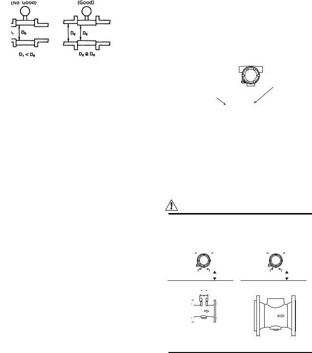
(4) Pipeline Diameter and digitalYEWFLO
The process pipeline inner diameter should be slightly larger than the vortex flowmeter inner diameter, schedule 40 or lower pipe should be used for 1/2 to 2 inch flowmeters and schedule 80 or lower pipes for 3 to 8 inch flowmeters.
(No Good) |
|
(Good) |
D1 |
|
D2 |
|
|
D1 |
|
D2 |
|
||
|
|
|
|
|
|
|
|
|
|
|
|
|
|
|
|
|
|
|
|
||
|
|
|
|
|
|
|
|
|
|
|
|
|
|
|
|
|
|||||
|
|
D1 < D2 |
|
|
|
|
||||
|
|
|
|
|
D1 D2 |
|||||
F020305.EPS
Figure 2.6
(5) Waterproof Construction
The vortex flowmeter is of IP67, NEMA4X
tightprotection. However, it cannot be used under water.
2.4 Piping to Improve Durability
(1) Pipe cleaning
•Flushing of pipe line (Cleaning)
Flush and clean scale, incrustation and sludge on the inside of pipe wall for newly installed pipe line and repaired pipe line before the operation.
•Fluid Carrying Solids
Do not measure fluids that carry solids (e.g. sand and pebbles). Make sure users periodically remove solids adhering to the vortex shedder.
•Obstruction of flow fluids may cause to make a chemical reaction and the fluid will be crystallized and hardened, and be deposited on the pipe wall and shedder bar.
In those cases, clean shedder bar.
(2) Bypass piping
Installing a bypass, as illustrated in the figure below, permits the digitalYEWFLO to be checked or cleaned conveniently (vortex shedder, etc.).
Bypass shut-off valve
digitalYEWFLO
Flow 
Upstream shut-off valve |
|
Downstream shut-off valve |
F020401.EPS
Figure 2.7
2.5Cryogenic and High process Temperature Version Insulation
When you are using cryogenic type and high process temperature version of digitalYEWFLO Vortex Flowmeter (Option code/HT /LT), refer to illustrated insulation method as shown in Figure 2.8
2. INSTALLATION
(1) Installing Cryogenic Vortex Flowmeter
For cryogenic applications, use stainless steel mounting bolts and nuts to install the flowmeter. These can be ordered separately from YOKOGAWA. Cover the flowmeter body with heat insulating material so that the flowmeter can be maintained at ultra-low temperatures (refer to the Figure 2.8).
(2) Maintenance for Cryogenic Applications
DY/LT uses special materials that produce vortex flowmeter for cryogenic applications. When you are replacing a shedder bar, specify cryogenic type shedder bar. To avoid condensing in the terminal box, ensure that the wire connecting port is well sealed.
Bracket
Cold insulating material
F020501.EPS
Figure 2.8
(3)Installing High Process Temperature Vortex Flowmeter
Installation of the flowmeter is the same as the standard type. Cover the flowmeter body with heat insulating material following instruction of “CAUTION”.
CAUTION
Keep the upper limit of heat insulating material to prevent overheating of the terminal box.
Seal the heat insulating material to avoid hot-air leakage.
|
|
|
|
|
|
|
|
|
|
|
|
|
|
|
|
|
|
|
|
|
|
|
|
|
|
|
|
|
|
|
|
|
|
|
|
|
|
|
|
|
|
|
|
|
|
|
|
|
|
|
|
|
|
|
|
|
|
|
|
|
|
|
|
|
|
|
|
|
|
|
|
|
|
|
|
|
|
|
|
|
|
|
|
|
|
|
|
|
|
|
|
|
|
|
|
|
|
|
|
|
|
|
|
|
|
|
|
|
|
|
|
|
|
|
|
|
|
|
|
|
|
|
|
|
|
|
|
|
|
|
|
|
|
|
|
|
|
|
|
|
|
|
|
|
|
|
|
|
|
|
|
|
|
|
|
|
|
|
|
|
|
|
|
|
|
|
|
|
|
|
|
|
|
|
|
|
|
|
|
|
|
|
|
|
|
|
|
|
|
|
|
|
|
|
|
|
|
|
|
|
|
|
|
|
|
|
|
|
|
|
|
|
|
|
|
|
|
|
|
|
|
|
|
|
|
|
|
|
|
|
|
|
|
|
|
|
|
|
|
|
|
|
|
|
|
|
|
|
|
|
|
|
|
|
|
|
|
|
|
|
|
50mm min. |
|
|
|
|
|
|
|
|
|
|
|
|
|
|
50mm min. |
||
UPPER LIMIT OF |
|
|
|
|
|
|
|
|
|
|
|
|
UPPER LIMIT OF |
|
|
|
|
|
|
|
|
|
|
|||||||||||
HEAT INSULATING |
|
|
|
|
|
|
|
|
|
|
|
|
HEAT INSULATING |
|
|
|
|
|
|
|
|
|
||||||||||||
|
|
|
|
|
|
|
|
|
|
|
|
|||||||||||||||||||||||
MATERIAL |
|
|
|
|
|
|
|
|
|
|
|
|
MATERIAL |
|
|
|
|
|
|
|
|
|
||||||||||||
|
|
|
|
|
|
|
|
|
|
|
|
|
|
|
|
|
|
|
|
|
|
|
|
|
|
|
|
|
|
|
|
|
|
|
|
|
|
|
|
|
|
|
|
|
|
|
|
|
|
|
|
|
|
|
|
|
|
|
|
|
|
|
|
|
|
|
|
|
|
|
|
|
|
|
|
|
|
|
|
|
|
|
|
|
|
|
|
|
|
|
|
|
|
|
|
|
|
|
|
|
|
|
|
|
|
|
|
|
|
|
|
|
|
|
|
|
|
|
|
|
|
|
|
|
|
|
|
|
|
|
|
|
|
|
|
|
|
|
|
|
|
|
|
|
|
|
|
|
|
|
|
|
|
|
|
|
|
|
|
|
|
|
|
|
|
|
|
|
|
|
|
|
|
|
|
|
|
|
|
|
|
|
|
|
|
|
|
|
|
|
|
|
|
|
|
|
|
|
|
|
|
|
|
|
|
|
|
|
|
|
|
|
|
|
|
|
|
|
|
|
|
|
|
|
|
|
|
|
|
|
|
|
|
|
|
|
|
|
|
|
|
|
|
|
Nominal Size: 100mm or under
Nominal Size: 150mm or over
F020501a.EPS
(4)Maintenance for High Process Temperature Applications
DY/HT uses special materials that produce vortex flowmeter for High Process Temperature applications When you are replacing a shedder bar or a gasket, specify High Process Temperature type.
2-5 |
IM 1F6A0-01E |
2.6Installing the Vortex Flowmeter
WARNING
The Vortex Flowmeter is a heavy instrument. Please be careful to prevent persons from injuring whin it is handled.
Before installing the instrument verify the following. The direction of flow should match to the arrow mark on the instrument body. When changing the orientation of the terminal box, refer to "7.1."
Installation of Vortex flowmeter of the wafer and flange type is shown in Table 2.3.
When installing the wafer type vortex flowmeter, it is important to align the instrument bore with the inner diameter of the adjacent piping.
To establish alignment, use the four collars supplied with the instrument.
1.Four collars are supplied for 1/2 inch (15mm) to 1- 1/ 2inch (40mm), 2 inch of JIS 10K or ANSI class 150 or JPI class 150, and 3 inch of ANSI class 150 or JPI class 150. Install the instrument as illustrated in Table 2.2.
2.If the adjacent flanges have eight bolt holes, insert the stud bolts in the holes on the instrument shoulder. Refer to Figure 2.9.
Stainless steel stud bolts and nuts are available on order. When they are to be supplied by the user, refer to Table 2.2 for stud bolt length. Gaskets must be supplied by the user.
3.Gasket:
Avoid mounting gaskets which protrude into the pipeline. This may cause inaccurate readings.
Use gaskets with bolt holes, even if digitalYEWFLO is of the wafer type. Refer to Figure 2.10.
When using a spiral gasket (without bolt holes), confirm the size with the gasket-manufacturer, as standard items may not be used for certain flange ratings.
2. INSTALLATION
Table 2.2
Size |
|
Major Diameter of |
Length |
|
mm |
Flange Rating |
External Threed of |
||
R(mm) |
||||
(inch) |
|
Stud Bolt d (mm) |
|
|
15mm |
JIS 10K, 20K/DIN 10, |
|
|
|
(1/2B) |
16,25,40 |
12 |
160 |
|
|
JIS 40K |
16 |
160 |
|
|
ANSI 150, 300, 600 |
12.7 |
155 |
|
|
|
|
|
|
25mm |
JIS 10K, 20K, 40K |
16 |
160 |
|
(1B) |
ANSI 150 |
12.7 |
155 |
|
|
ANSI 300, 600 |
15.9 |
160 |
|
|
DIN 10, 16, 25, 40 |
12 |
160 |
|
|
|
|
|
|
40mm |
JIS 10K, 20K/DIN 10, |
16 |
160 |
|
(1-1/2B) |
16, 25, 40 |
|||
|
JIS 40K |
20 |
170 |
|
|
ANSI 150 |
12.7 |
155 |
|
|
ANSI 300, 600 |
19.1 |
170 |
|
|
|
|
|
|
50mm |
JIS 10K, 20K, 40K/ |
16 |
|
|
(2B) |
DIN 10, 16, 25, 40 |
200 |
||
|
ANSI 150, 300, 600 |
15.9 |
||
|
|
|||
|
|
|
|
|
80mm |
JIS 10K/DIN 10, 16, |
16 |
220 |
|
(3B) |
25, 40 |
|||
|
JIS 20K, 40K |
20 |
|
|
|
ANSI 150 |
15.9 |
240 |
|
|
ANSI 300, 600 |
19.1 |
|
|
|
|
|
|
|
100mm |
JIS 10K/DIN 10, 16 |
16 |
220 |
|
(4B) |
JIS 20K/DIN 25, 40 |
20 |
240 |
|
|
JIS 40K |
22 |
270 |
|
|
ANSI 150 |
15.9 |
240 |
|
|
ANSI 300 |
19.1 |
240 |
|
|
ANSI 600 |
22.2 |
270 |
|
|
|
|
|
T020601.EPS
LengthR
d
Stud Bolt
Collar
F020601.EPS
Figure 2.9
Pipeline Flange
Pipeline
F020602.EPS
Figure 2.10
2-6 |
IM 1F6A0-01E |
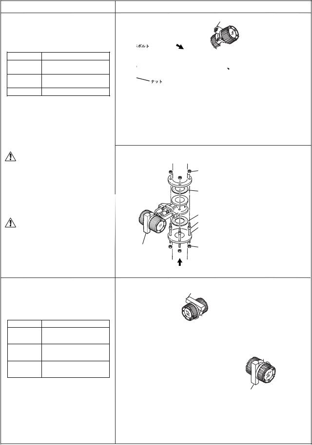
2. INSTALLATION
Table 2.3(a) Installation of Wafer Type Vortex Flowmeter
Wafer type
When Installation Collar are required, the installation vortex flowmeters applied to the following line sizes and flange ratings.
Size mm(inch) |
Flange Rating |
15 to 40
All ratings
(1/2 to 1-1/2)
50(2)
JIS 10K, ANSI class 150,
DIN PN10 to PN40
80(3) ANSI class 150, JPI class 150
|
Description |
|
Horizontal Installation |
Electrical Connection |
|
Flow |
Flange |
|
Direction |
|
|
Nut |
|
Flange |
Gasket
Collar
Gasket
(1)Insert four collar on each of the four bolts and check that all four collars contact the outside diameter of the flowmeter body.
(2)Tighten the four bolts uniformly. Check for leakage from the flange connections.
Stud Bolt (4 pcs.)
Nut
WARNING
The inside diameter of the gasket must be larger than the pipe inner diameter so that it will not disturb the flow in the pipeline.
WARNING
When installing the Flowmeter vertically in the open air, change the electrical connection port direction to the ground. If the electrical connection port is installed upwards, rain water might leak in.
Vertical Installation
Nut
|
Gasket |
|
Gasket |
|
Collar |
|
Stud Bolt |
|
(4 pcs.) |
Electrical |
Nut |
connection |
|
|
Flow Direction |
(1)Insert two each collars on each of the lower two bolts.
(2)Place the flowmeter body on the lower two bolts.
(3)Tighten the four bolts (including upper two bolts) and nuts uniformly.
(4)Check for leakage from the flange connections.
When Installation Collars are not required,the installation vortex flowmeters applied to the following line sizes and flanges.
Size mm(inch) |
Flange Rating |
JIS 20K, 40K
50(2) ANSI class 300,600 JPI class 300,600
JIS 10K, 20K, 40K 80(3) ANSI class 300, 600
JPI class 300,600
JIS 10K, 20, 40K
100(4) ANSI class 150, 300, 600 JPI class 150,300,600
Horizontal Installation |
Vertical Installation |
|
Flow |
Electrical Connection |
|
Direction |
|
|
Nut |
Bolt Hole |
|
Flange |
|
|
Stud Bolt (8 pcs.)
Flange
Gasket
Gasket
Nut
(1)Insert two stud bolts in the bolt holes on the flowmeter shoulder to align the instrument body with the inner diameter of the adjacent piping.
(2)Tighten all bolts uniformly and check that there is no leakage between the instrument and the flanges.
Electrical
Connection
Flow Direction
T020602.EPS
2-7 |
IM 1F6A0-01E |
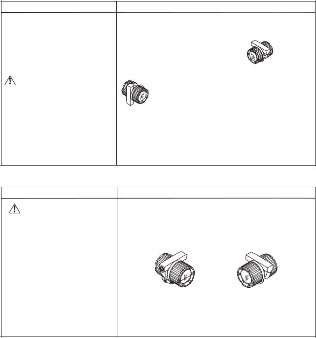
Table 2.3(b) Installation of Flange Type Vortex Flowmeter
Flange type
Use the stud bolts and nuts supplied with the flowmeter of the user.
The gaskets should be supplied by the user.
CAUTION
The inside diameter of the gasket must be larger than the pipe inner diameter so that it will not disturb the flow in the pipeline.
2. INSTALLATION
Description
Horizontal Installation
Flow Direction
Flange
Nut |
Flange |
Stud Bolt
Gasket
Nut
Gasket
Flow Direction
Vertical Installation
T020603.EPS
Table 2.3(c) Installation of remote Type Converter
Remote type converter
CAUTION
A signal cable (DYC) is used between the remote type flowmeter and the converter. The maximum signal cable length is 97.5ft (30m).
Description
The converter is mounted on a 2-inch (60.5mm outer dia.) stanchion or horizontal pipe.
Do not mount the converter on a vertical pipe. It makes wiring and maintenance difficult.
The converter mounting orientation can be changed as illustrated below.
Stanchion |
Mounting |
Horizontal Pipe |
Mounting |
Nut
Bracket
2-inch Pipe
U-Bolt
T020604.EPS
2-8 |
IM 1F6A0-01E |
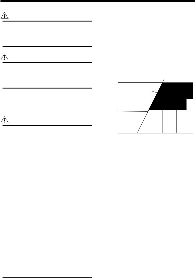
3. WIRING
3. WIRING
WARNING
The wiring of the vortex flowmeter must be performed by expert engineer or skilled personnel. No operator shall be permitted to perform procedures relating to wiring.
CAUTION
Once all wiring is complete, check the connections before applying power to the instrument. Improper arrangements or wiring may cause a unit malfunction or damage.
3.1 Wiring Precautions
Be sure to observe the following precautions when wiring:
CAUTION
•In cases where the ambient temperature exceeds 50°C (122°F), use external heat-
resistant wiring with a maximum allowable temperature of 70°C (158°F) or above.
•Do not connect cables outdoors in wet weather in order to prevent damage from condensation and to protect the insulation.
•Do not splice the cable between the flowtube terminal and the converter if it is too short. Replace the short cable with a cable that is the appropriate length.
•All the cable ends must be provided with round crimp-on terminals and be securely wired.
•Be sure to turn power off before opening the cover.
•Before turning the power on, tighten the cover securely.
•Explosion protected types must be wired in accordance with specific requirement (and, in certain countries, legal regulations) in order to preserve the effectiveness of their explosion protected features.
•The terminal box cover is locked by the clamp. In case of opening the terminal box cover, use the hexagonal wrench attached.
•Be sure to lock the cover by the clamp using the hexagonal wrench attached after installing the cover.
3.2 Wiring for Output Condition
Table 3.1 shows the connection method of several output conditions.
(1) Analog Output (4 to 20 mA DC)
This converter uses the same two wires for both, the signal and power supply. A DC power supply is required in a transmission loop. The total leadwire resistance including the instrument load and power distributor (supplied by the user) must conform to a value in the permissible load resistance range. Refer to Figure 3.1 shows.
|
600 |
|
|
|
|
|
|
|
|
|
|
|
|
|
|
E–10.5 |
|
|
|
|
|
|
|
||
(Ω) |
R= |
|
|
|
Communication |
|
|
|||||
0.0236 |
|
|
|
|
|
|||||||
|
|
|
Applicable |
range |
|
|||||||
R |
|
|
|
|
|
|
|
BRAIN and |
HART |
|
||
resistance |
|
|
|
|
|
|
|
|
||||
250 |
|
|
|
|
|
|
|
|
|
|
|
|
|
|
|
|
|
|
|
|
|
|
|
||
Load |
|
|
|
|
|
|
|
|
|
|
|
|
|
|
|
|
|
|
|
|
|
|
|
|
|
|
10.5 |
16.4 |
24.7 |
30 |
|
|
42 |
|||||
|
Power Supply Voltage E (V) |
|
||||||||||
|
|
|
|
|
|
|
|
|
|
F030201.EPS |
||
Figure 3.1 Relationship between Power Supply Voltage and Load Resistance (4 to 20 mA DC Output)
(2) Pulse output and Alarm, Status Output
This version uses three wires between the converter and the power supply. A DC power and load resistance are required, and pulse output is connected to a totalizer or an electric counter. Low level of the pulse output is 0 to 2V. No communication is possible over a transmission line. Communication via the amplifier board is always possible irrespective of the wiring condition.
(3) Simultaneous Analog-Pulse Output
When using digitalYEWFLO in the simultaneous analog -pulse output mode, the communicable distance of the transmission line is restricted on the wiring method. Table 3.1 shows the examples of connection for this output mode. Communication via the amplifier board is always possible irrespective of the wiring condition.
3-1 |
IM 1F6A0-01E |

3. WIRING
IMPORTANT
For pulse output and the simultaneous analog-pulse output ,use the load resistance. Refer to Table 3.1.
3.3 Connection
Table 3.1 shows the connection sample of connection for power supply and load resistance. The terminal position of each connection is shown in Figure 3.2.
Integral type |
Remote type |
TInput Terminal from builtin temperature sensor
|
A |
Input Terminals from |
Supply |
4 to 20 mA DC Output Power Supply |
|
B |
vortex detector |
|
and Output Signal Terminals |
|
– |
|||
|
C |
Common Terminal |
Pulse |
Pulse Output Terminal |
|
|
|
|
|
|
|
|
|
F030301.EPS |
Figure 3.2 |
|
|
||
3-2 |
IM 1F6A0-01E |

3. WIRING
Table 3.1 The connection example for simultaneous analog and pulse and alarm, status output.
Connection |
Description |
Analog Output
In this case, Communication is possible (up to a distance of 2km when a CEV cable is used.)
Pulse Output
In this case,
No communication is possible.
Status Output
Alarm Output
In this case,
No communication is possible.
digitalYEWFLO Electrical Terminal
SUPPLY +
–
PULSE +
digitalYEWFLO Electrical Terminal Shielded Cable
SUPPLY +
–
PULSE +
digitalYEWFLO Electrical Terminal Shielded Cable
SUPPLY +
–
PULSE +
Distributor
+24V DC
–250Ω
Use the Three-wire shielded cable.
E
*1
*2 R Electric counter
Use the Three-wire shielded cable.
E
Relay
Mognetic
valve
External Power supply 30V DC, 120mA max (Contact Rating)
AC power supply
Simultaneous
Analog
-Pulse Output
Example 1
In this case, Communica -tion is possible(up to a distance of 2km when a CEV cable is used).
Example 2
In this case, Communica -tion is possible (up to a distance of 200m when a CEV cable is used) and R = 1kΩ).
Example 3
In this case, No communi -cation is possible (when shielded cable is not used).
When analog and pulse output are used, the length of communication line is subjected to wiring conditions. Refer to example 1 to 3. If the communication carries out from amplifier, no need to consider wiring conditions.
|
|
Distributor |
(or communication medium : ex. EP card) |
|||
Shielded Cable |
|
24V DC |
For the shielded cables in this example of |
|||
SUPPLY + |
|
flowmeter installation, use two-wire separately |
||||
|
|
|||||
|
|
shielded cables. |
|
|||
– |
|
250Ω |
|
|||
*2 R |
|
|
|
|||
E(10.5 to 30V DC) |
This supply voltage requires a power sourse |
|||||
PULSE + |
|
|||||
|
Counting input |
with a maximum output current of no less than |
||||
|
|
Common |
E/R. |
|
|
|
digitalYEWFLO Electrical Terminal |
|
Electric counter*1(or communication medium : ex. EP card) |
||||
|
|
|||||
|
|
Recorder or |
For the shielded cables in this |
|||
|
|
example of flowmeter installation, |
||||
Shielded Cable |
|
other instrument |
||||
|
use two-wire separately shielded |
|||||
|
250Ω |
|
|
|||
SUPPLY + |
|
|
cables. |
|
||
|
E(16.4 to 30V DC) |
|
||||
|
This supply voltage requires a power |
|||||
|
R*2 |
|
||||
– |
|
|
sourse with a maximum output current |
|||
|
Counting input |
|||||
PULSE + |
|
Common |
of no less than E/R+25mA. |
|||
|
The supply voltage requires output |
|||||
|
|
Electric counter |
||||
|
|
impedance no more than 1/1000 of R |
||||
digitalYEWFLO Electrical Terminal |
|
|
*1 |
(load resistance). |
||
|
|
|
Recorder or |
|
||
|
|
|
other instrument |
|
||
SUPPLY + |
|
250Ω |
|
|
This supply voltage requires |
|
|
|
E(16.4 to 30V DC) |
||||
|
R*2 |
|
|
a power sourse with a |
||
– |
|
Counting input |
||||
|
|
maximum output current of |
||||
PULSE + |
|
|
Common |
|
no less than E/R+25mA. |
|
|
|
|
|
|||
Electric counter *1
The range of load resistance R for the pulse output.
The load resistance of pulse output should be used to 1kΩ, 2W.
If no translation of the pulse output possible by the cable length or the frequency of the pluse output, the load resistance should be selected by calculation as shown below.
E (V) |
0.1 |
Example of CEV cable capacitance |
|
|
R (kΩ) |
|
|
120 |
|
C ( F ) × f ( kHz ) |
0.1 F/km |
|
|
E |
2 |
(V) |
Where |
C = Cable capacitance ( F) |
|
P (mW) = |
|
E = Supply voltage (V) |
|||
|
R (kΩ) |
|||||
|
|
f = Frequency of pulse output (kHz) |
P = Power ratio of the load resistance |
|||
|
|
|
|
|
R = Value of load resistance (kΩ) |
(mW) |
|
|
|
|
|||
*1 |
: To avoid the influence of external noise, use an electric counter which fits to the pulse frequency. |
|
||||
*2 |
: Resistor is not necessary in case of an electric counter which can receive contact pulse signal directly. |
T030301.EPS |
||||
3-3 |
IM 1F6A0-01E |
3.4 Wiring Cables and Wires
The following should be taken into consideration when selecting cables for use between the converter and distributor.
(1)Use 600V PVC insulated wire or equivalent standard wire or cable.
(2)Use shielded wire in areas susceptible to electrical noise (both analog and pulse output versions).
(3)In areas with high or low ambient temperatures, use wires or cables suitable for such temperatures.
(4)In atmospheres where oils or solvents, corrosive gases or liquids may be present, use suitable wires or cables.
(5)Use cable which withstand temperature up to 60°C and more, when ambient temperature is more than 60°C.
IMPORTANT
For the remote type, use DYC signal cable to connect the converter and remote type flowmeter(DY-N).
3.5Connection of the Remote Type Signal Cable
The remote type signal cable is shown in Figure 3.3 and 3.4, and the terminal is shown in Figure 3.5.
The maximum cable length is 30 m (97.5 feet).
Remove terminal box cover and wiring connection dust-cap before wiring.
For remote type the converter has two electrical connections (cable inlets). Use the left connection as viewed from the terminal box for the DYC signal cable and the right connection for the transmission cable.
If a signal cable kit is supplied by YOKOGAWA, both ends of the cable must be finished in accordance with the following instructions as shown in 3.6.1 and 3.6.2.
CAUTION
After completing the signal cable connections, install the shielded cover to signal cable terminal as shown in Figure 3.6.
|
|
|
|
|
3. WIRING |
|
|
|
|
|
Unit : mm |
(Black) (White) (Red) |
(Yellow) |
|
|
(Yellow) (Red) (White) (Black) |
|
80 |
70 |
|
70 |
|
80 |
|
|
|
|||
|
60 |
|
60 |
|
|
|
50 |
|
|
50 |
|
|
20 |
|
|
25 |
95 |
|
|
|
|
||
|
|
|
|
|
(Blue) |
Flowmeter |
|
Specified |
|
|
Converter |
|
|
Length (L) |
|
|
|
|
|
30m (max.) |
|
|
|
|
DYC |
|
|
|
|
|
|
|
|
|
F030501.EPS |
Figure 3.3 DYC Signal Cable |
|
|
|
||
|
|
Outer shield |
|
|
|
To Flowmeter |
|
|
|
|
To Converter |
T |
|
|
|
|
T |
A |
|
|
|
|
A |
B |
|
|
|
|
B |
|
|
Inner shield |
|
|
C |
C |
|
|
|
|
|
|
|
|
|
|
|
T: Only for / MV |
|
|
|
F030502.EPS |
|
|
|
|
|
|
|
Figure 3.4 Construction of Remote Type Signal Cable |
|||||
T |
|
T |
|
|
|
A |
|
A |
|
|
|
B |
|
B |
|
|
|
|
|
C |
|
|
|
C |
|
|
|
|
|
Flowmeter(DY-N) |
|
|
Converter(DYA) |
||
|
T: Only for /MV |
|
|
||
TInput Terminal from builtin temperature sensor
A |
Input Terminals from |
Supply |
4 to 20 mA DC Output Power Supply |
B |
vortex detector |
|
and Output Signal Terminals |
– |
|||
C |
Common Terminal |
Pulse |
Pulse Output Terminal |
|
|
|
|
|
|
|
F030503.EPS |
Figure 3.5 Terminal of Detector and Converter
Vortex Flow Converter
Signal Cable(DYC)
Shield Cover
Power Vable
F030504.EPS
Figure 3.6 Shielded Cover
3-4 |
IM 1F6A0-01E |

3. WIRING
3.6 Method of Finishing the Signal Cable End(DYC)
3.6.1 For |
Vortex Flowmeter (DY-N) |
|
|
|
Description |
Figure |
|
1 |
Strip off the outer polyethylene jacket, outer braided |
5 (0.2) 10 (0.4) |
Unit : mm |
|
shield and inner jacket, and inner braided shield as |
|
(approx. inches) |
|
per the dimensions below. |
5 (0.2) |
|
|
|
|
|
|
|
90 (3.5) |
|
|
|
Black Conductive Layer |
|
|
|
T (yellow) |
|
2 |
Strip off the black conductive layer convering two |
T (Yellow) |
40 (1.6)5 (0.2) |
|
wires completely, as per the dimensions below. |
3 (0.1) |
|
|
A (Red) |
or less |
|
|
Twist each of the conductor and drain wires so that |
||
|
|
|
|
|
there are no free strands. |
|
|
50 (2.0)  Black Conductive Layer
60 (2.4)
B (White)
3Do not short-circuit the conductive layer and the terminals (A, B, C and T).
4 |
Strip off about 5 mm (0.2 in.) of insulation for each |
|
Drain wires |
|
of wires A, B, and T, and twist the strands of each |
C |
T (Yellow) |
|
wire. Twist the inner and outer drain wires together. |
A (Red) |
|
|
|
B (White) |
5 (0.2) |
|
|
5 (0.2) |
5 (0.2) |
|
|
|
|
5 |
Slide FEP (fluorinated ethylene propylene) tubing |
5 (0.2) |
FEP Insulation Tubing |
|
over the twisted inner and outer drain wires C until |
C |
(Black) |
|
|
||
|
the tubing cannot be slid any further, and then cut |
|
|
|
off the tubing leaving 5 mm (0.2 in.) of the stranded |
|
T (Yellow) |
|
drain wires exposed. |
|
A (Red) |
|
|
|
B (White) |
6 |
Slide heat shrinkable tubing over the cable end so |
C |
Heat Shrinkable Tubing |
|
that the tubing covers the braided shield and |
|
|
|
overlaps both the polyethylene jacket and loose |
|
T (Yellow) |
|
wires A, B, C, and T. |
|
|
|
|
A (Red) |
|
|
|
|
B (White) |
7 |
Slide a short piece of heat shrinkable tubing over |
Crimp and Solder Here |
|
|
each of wires A, B, C, and T. Install a crimp-on |
Lug tip |
Heat Shrinkable Tubing |
|
|
||
|
terminal lug at the tip of each wire. Crimp and |
|
|
|
solder each lug. |
10 |
|
8 Slide each short piece of heat shrinkable tubing over the crimp sleeve. Heat all pieces of heat shrinkable tubing with a heat blower or dryer.
Heat Shrinkable Tubing
9 Attach an identification label to the end of the cable.
(*1): Only for /MV
NOTE
Check that the insulation resistance between each wire including the inner shield is 10MΩ or greater at 500V DC. Ensure that both ends of the wires are disconnected (open-circuited) during the check.
CAUTION
80 |
|
Unit : mm |
BLACK (C) |
5 5 10 |
|
WHITE (B) |
|
|
RED (A) |
3MAX |
120 |
|
||
|
|
|
Yellow(T) 50 |
|
|
60 |
|
|
70 |
|
F030601.EPS |
|
|
Figure 3.7
T030601.EPS
NOTE
In case that the cable end finish parts assembly is necessary after delivery, contact your nearest Yokogawa sales office or the sales representative from which you purchased the product. The parts number of DYC cable end finish parts assembly:
Standard type: F9399AB Multivariable type (/MV): F9399AD
Do not touch the '' conductive layer" (black area covering the signal cables A and B) to the converter case, terminal, and other leadwires. If it is touched, operation of the converter may be incorrect. When the cable is terminated, remove the conductive layer properly.
3-5 |
IM 1F6A0-01E |

|
|
|
|
|
|
3. WIRING |
3.6.2 |
For |
Vortex Flow Converter (DYA) |
|
|
|
|
|
|
Description |
|
|
Figure |
|
|
1 |
Strip off the outer polyethylene jacket, outer braided |
|
15 (0.6) 10 (0.4) |
Unit : mm |
|
|
|
shield and inner jacket, and inner braided shield as |
|
|
|
(approx. inches) |
|
|
per the dimensions as shown. |
|
|
|
|
|
|
|
|
95 |
5 (0.2) |
|
|
|
|
|
(3.7) |
|
|
|
|
|
Black Conductive |
T (yellow) |
|
|
|
|
|
Layer |
|
|
|
|
|
|
|
|
|
|
|
2 |
Cut of the black conductive layers(convering the |
|
|
|
|
|
|
two wires) completely, as per the dimensions below. |
B (White) |
|
3 (0.1) or less |
Black |
|
|
Twist each of the conductor and drain wires so that |
|
|||
|
|
A (Red) |
|
40 (1.6) |
||
|
|
there are no free strands. |
|
Conductive Layer |
||
|
|
T (Yellow(*1)) |
|
50 (2.0) |
5 (0.2) |
|
|
|
|
|
|
||
|
|
|
|
|
60 (2.4) |
|
3Do not short-circuit the conductive layer and the terminals (A, B, C, G and T).
4 |
Strip off about 5 mm (0.2 in.) of insulation for each |
5 (0.2) |
|
|
of wires A, B, and T, and twist the strands of each |
G 5 (0.2) |
Drain wires |
|
wire. |
C |
|
|
|
|
T (Yellow) |
|
|
5 (0.2) |
A (Red) |
|
|
|
B (White) |
5 |
Slide black FEP (fluorinated ethylene propylene) |
5 (0.2) |
|
|
|
tubing over the inner shield drain wire C and blue |
|
FEP Insulation Tubing (Black) |
|
|
|
|
FEP Insulation Tubing (Blue) |
|
|
FEP tubing over outer shield drain wire G until |
G |
|
|
|
|
|
||
|
the tubing cannot be slid any further, and then cut |
C |
|
|
|
|
|
|
|
|
off the tubing leaving 5 mm (0.2 in.) of the drain |
5 (0.2) |
T (Yellow) |
|
|
wires exposed. |
A (Red) |
||
|
|
|
|
B (White) |
6 |
Slide heat shrinkable tubing over the cable end so |
G |
|
|
|
that the tubing covers the braided shield and |
C |
A T |
|
|
B |
|
||
|
overlaps both the polyethylene jacket and loose |
|
|
|
|
|
15 (0.6) |
25 (1.0) |
|
|
wires A, B, C, G, and T. |
|
||
|
|
|
|
|
|
|
|
|
Heat Shrinkable Tubing |
7 |
Slide a short piece of heat shrinkable tubing over |
Lug-Tips |
|
Crimp and Solder Heat-shrinkable tubing |
|
each of wires A, B, C, G, and T. Install a crimp-on |
|
|
|
|
terminal lug at the tip of each wire. Crimp and |
|
10 |
|
|
solder each lug. |
|
|
|
|
|
(0.4) |
|
|
|
|
|
|
|
8 Slide each short piece of heat
shrinkable tubing over the crimp sleeve. Heat all pieces of heat shrinkable tubing with a heat blower or dryer.
Heat Shrinkable Tubing
9 Attach an identification label to the end of the cable.
(*1): Only for /MV
NOTE
T030602.EPS
95 |
Unit : mm |
NOTE |
BLUE (G) |
|
|
Check that the insulation resistance between each wire including the inner shield is 10MΩ or greater at 500V DC. Ensure that both ends of the wires are disconnected (opencircuited) during the check.
BLACK (C) |
|
|
In case that the cable end finish parts |
|
|
|
|
WHITE (B) |
|
|
assembly is necessary after delivery, |
RED (A) |
3 |
|
contact your nearest Yokogawa sales |
|
MAX |
|
|
|
|
|
office or the sales representative from |
YELOW(T) 50 |
|
which you purchased the product. |
|
|
10 |
10 |
|
|
120 |
||
60 |
5 |
|
The parts number of DYC cable end |
70 |
|
|
finish parts assembly: |
80 |
|
|
|
F030602.EPS
|
Standard type: F9399AA |
Figure 3.8 |
Multivariable type (/MV): F9399AC |
|
|
|
|
CAUTION
Do not touch the '' conductive layer" (black area covering the signal cables A and B) to the converter case, terminal, and other leadwires. If it is touched, operation of the converter may be incorrect. When the cable is terminated, remove the conductive layer properly.
3-6 |
IM 1F6A0-01E |

3.7 Wiring Cautions
(1)Lay wiring as far as possible from electrical noise sources such as large transformers, motors and power supplies.
(2)It is recommended that crimp-on type solderless lugs be used for large wire ends.
(3)For general use, it is recommended that conduits and ducts or racks be used to protect wiring from water or mechanical damage. A rigid steel conduit or flexible metal conduit is recommended. See Figure 3.9.
F030701.EPS
Figure 3.9
3. WIRING
3.8 Grounding
IMPORTANT
When a lightning protector (option code: /A) is selected, use a grounding resistance of 10Ω or less.
(1)The grounding terminals  are located on the inside and outside of the terminal area. Either terminal may be used.
(2)For pulse output version, ground the flowmeter. Also ground the shielded cable between the converter and the pulse receiver.
(3)Grounding should satisfy Class D requirements (ground resistance 100Ω or less).
(4)Use 600V PVC insulated wire for grounding.
Grounding
Integral Type |
terminals |
|
|
|
F030801.EPS |
Figure 3.10
3-7 |
IM 1F6A0-01E |

4. BASIC OPERATING PROCEDURES
4. BASIC OPERATING PROCEDURES
Data setting can be performed with the three keys on the front |
■ Description of unit indications and its votes. |
||||||
panel (SET,SHIFT and INC) or using a handheld |
Table 4.1 shows the description of unit indications and |
||||||
BRAIN(BT) terminal and HART communicator. |
it's votes. |
|
|
||||
4.1 |
Construction of the Display |
Table 4.1 |
Unit Indicator |
|
|||
Unit |
Upper Indication |
Lower Indication |
|||||
Figure 4.1 shows the configuration of the digitalYEWFLO |
|||||||
% |
|
|
|||||
display panel (if equipped). |
|
|
|
|
|||
|
|
m3 |
|
|
|||
|
|
|
|
|
|
||
|
|
|
1 Data Display |
|
|
|
|
|
|
|
Nm3 |
|
|
||
|
|
|
(Upper) |
N |
|
|
|
|
|
|
|
|
|
||
4 Unit Display |
|
|
Sm3 |
|
|
||
|
|
S |
|
|
|||
|
|
|
|
|
|
||
|
|
|
|
kg |
|
|
|
3 Alarm Display |
|
|
t |
|
|
||
2 Data Display |
|
|
/h |
|
|
||
|
SET |
/m |
|
|
|||
(Lower) |
|
|
|
||||
|
|
/s |
|
|
|||
|
|
SHIFT |
INC |
|
|
||
4 |
Unit Display |
/d |
|
|
|||
|
|
|
|
||||
|
|
|
|
°C |
|
(*1) |
|
|
|
|
|
(*1) Only for /MV |
T040101.EPS |
||
|
|
|
|
|
|||
5 Setting Keys
F040101.EPS
Figure 4.1 Construction of the Display
1 Data Display(Upper) : Displays flowrate data, setting data, total data.
2Data Display(Lower) : Displays total data, alarm data.
3Alarm Display : Displays alarm of a flow error
|
|
and a vibration error. |
4 |
Unit Display |
: Displays Flowrate unit. |
5 |
Setting Keys |
: These keys are used to change |
flow rate data displays and type of setting data.
4-1 |
IM 1F6A0-01E |

4. BASIC OPERATING PROCEDURES
4.2 Display Contents in Display Section
The display content items are classified in the following three items.
Table 4.2 |
Mode Name List |
||
|
|
|
|
|
Mode (status) Name |
Display Contents |
|
|
|
|
|
|
Flowrate display |
A mode in which instantaneous flow rates or totalized values are displayed. |
|
|
mode |
|
Display content is usually selected either in display content selection mode or by setting parameters |
|
|
|
via BRAIN communication. |
|
|
|
|
|
Setting mode |
In this mode, parameter contents are confirmed or data is updated using the setting section. The mode is |
|
|
|
|
changed to this mode when [SET] key is pressed in normal mode. |
|
|
|
|
|
Alarm number display |
This mode is overlapped when an alarm is occurring in display mode. The alarm number presentation to |
|
|
mode |
|
indicate alarm contents (about 2 sec) and the normal data display (about 4 sec ) are repeated alternatively. |
|
|
|
|
Mode represents that the system is in a state where the relevant setting or display is possible.
T040201.EPS
● Display Example
SET
SHIFT + SET
Flowrate Display Mode
UPPER |
LOWER |
Flow rate |
Total rate |
UPPER |
LOWER |
Flow rate (%) |
Blank |
This mode display can be selected below.
•Upper display : Flow rate
•Lower display : Total rate or Blank
Setting Mode
Switching of setting number
SHIFT
•This mode is used to check parameter content and rewrite data. This mode can be called up from the flowrate display mode by pressing the “SET” key.
•Setting item and setting number can be changed when pressing “SHFT” key.
•This mode can be called up by pressing “SET” key while pressing “SHIFT” key when setting mode is displayed.
Error Mode
NORMAL
INDICATION Alternately (4sec)
ERROR INDICATION (2sec)
•When an alarm situation occurs, this mode will replace the current mode (flow rate or setting mode) to show what type of alarm has occurred.
•Refer to “5.5 Error Code Lists” about the error descriptions and error No.
F040201.EPS
4-2 |
IM 1F6A0-01E |

4. BASIC OPERATING PROCEDURES
4.3Display Contents in Display Section
The display mode is a mode in which instantaneous flow rates or totalized flow are displayed. In display mode, there are three display modes as shown in Table 4.3.
Table 4.3 Display Mode
Name |
Contents |
Upper |
Lower |
|
Display |
Display |
|||
|
|
|||
|
|
|
|
|
% Display |
Instantaneous % flow rate is |
|
|
|
(Flow rate) |
displayed. |
|
|
|
|
|
|
|
|
Engineering |
Instantaneous flow rate in an |
|
|
|
Display Unit |
engineering unit is displayed. |
|
|
|
|
|
|
|
|
Totalized |
Totalized flow displayed |
|
|
|
Display |
without indicating the decimal |
|
|
|
|
point. |
|
|
|
|
|
|
|
|
% Display |
Instantaneous temperature is |
|
|
|
(Temperature) |
displayed. |
|
|
|
(*1) |
In this case, “t” is displayed |
|
|
|
|
simultaneously (Refer to |
|
|
|
|
Figure 4.2). |
|
|
|
|
|
|
|
|
Temperature |
Temperature value is |
|
|
|
display(*1) |
displayed. |
|
|
|
|
|
|
|
|
Blank |
------ |
|
|
|
|
|
|
|
|
(*1) When option code /MV is selected, |
|
T040301.EPS |
||
|
|
|||
this function is available.
F040301.EPS
Figure 4.2 Example
Display mode can be changed using the BT200 terminal or the indicator setting section.
•For operation using BT200, perform changes using the parameter item “ B30:UPPER DISP” and “B31:LOWER DISP” referring to section 5. Parameters.
•For operation using indicator, change B30 and B31 parameter item number to display an appropriate display.
IMPORTANT
After setting a parameter, keep the power on for at least 30 seconds.
If the power of flowmeter is turned off, a parameter setting is released.
4-3 |
IM 1F6A0-01E |

4. BASIC OPERATING PROCEDURES
4.3.1 Change the Display Mode from % Display to Engineering Unit
The display mode can be changed referring 5.3 parameter list.
|
Indication of % |
|
Indicate “ 01 ” of |
|
display. |
|
engineering unit |
|
|
|
referring 5.3 |
|
|
|
parameter list. |
|
SET |
|
SET |
SHIFT |
INC |
SHIFT |
INC |
Press “ SET ” key.
Enter the setting mode.
SET
SHIFT INC
Press “ SHIFT ” key.
Enter the parameter item.
SET
SHIFT INC
Press “ SET ” key.
Ensure the setting data.
SET
SHIFT INC
Press “ SET ” key.
Finish the setting.
SET
SHIFT INC
|
Press “ INC ” key any time. |
|
Press “ SET ” and “ SHIFT ” key. |
|
Indicate “ 30 ” |
|
Return to display |
|
referring 5.3 |
|
mode. |
|
parameter list. |
|
|
|
SET |
|
SET |
SHIFT |
INC |
SHIFT |
INC |
Press “ SET ” key.
Enter the data input item.

 SET
SET
SHIFT INC
Press “ INC ” key.
IMPORTANT
After setting a parameter, keep the power on for at least 30 seconds.
If the power of flowmeter is turned off, a parameter setting is released.
F040302.EPS
4-4 |
IM 1F6A0-01E |
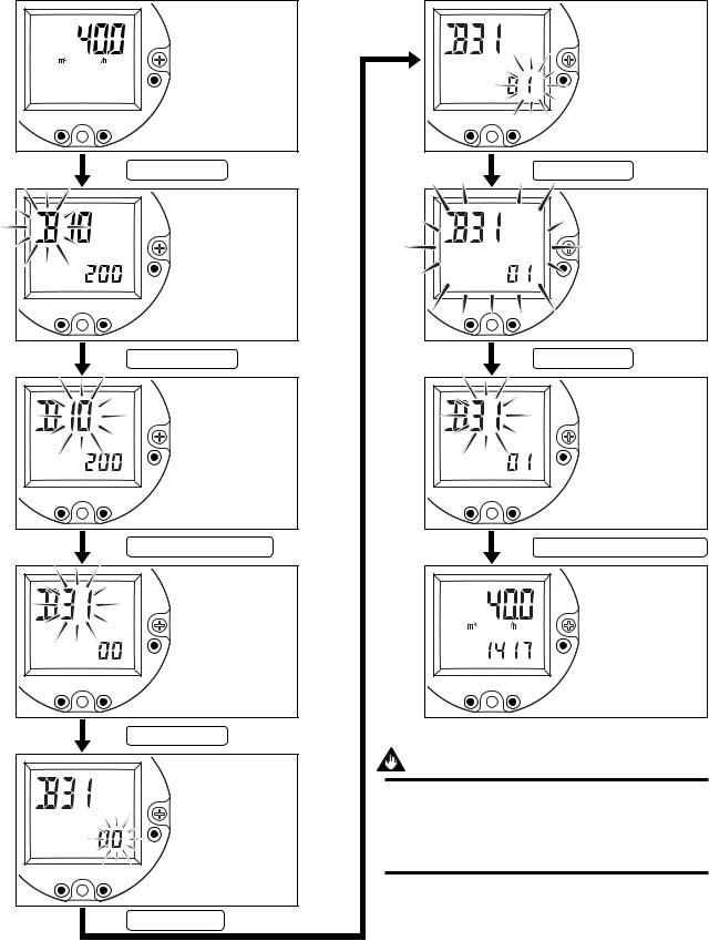
4. BASIC OPERATING PROCEDURES
4.3.2 Indicate the Total Rate in the Lower Display
The display mode can be changed referring 5.3 parameter list.
|
Indication of |
|
engineering unit |
|
display. |
|
Lower display is |
SET |
“ Blank ”. |
SHIFT INC
Press “ SET ” key.
Enter to the setting mode.
SET
SHIFT INC
Press “ SHIFT ” key.
Enter to the parameter item.
SET
SHIFT INC
Press “ INC ” key any time.
Indicate “ 31 ” referring 5.3 parameter list.
Indicate “ 01 ” of lower the display item referring 5.3 parameter list.
SET
SHIFT INC
Press “ SET ” key.
Ensure the setting data.
SET
SHIFT INC
Press “ SET ” key.
Finish the setting.
SET
SHIFT INC
Press “ SET ” and “ SHIFT ” key.
Return to display mode.
|
SET |
|
SET |
SHIFT |
INC |
SHIFT |
INC |
Press “ SET ” key.
Enter the data input item.
SET
SHIFT INC
Press “ INC ” key.
IMPORTANT
After setting a parameter, keep the power on for at least 30 seconds.
If the power of flowmeter is turned off, a parameter setting is released.
F040303.EPS
4-5 |
IM 1F6A0-01E |

4.4 Setting Mode
The setting mode is used for checking parameters and
rewriting data. The following is an overview of the setting
mode.
NOTE
•Refer to 5.3 Parameter List and 5.4 Parameter description for information on how to change setting.
4.4.1 Structure of Setting Mode Display
Simple parameter sheet
IN this sheet, a setting flow chart and the parameter list required to operate digitalYEWFLO is indicated.
Item number
Change item number using “SHIFT” key and “INC”key.
SET
Data number
SHIFT INC Change the data number using “SHIFT” key and “INC” key.
F040401.EPS
Flowrate Display Mode
|
|
|
|
|
|
|
|
|
|
|
|
|
|
|
|
|
|
|
SHIFT+SET |
|
SET |
|
|
|
|
|
|
|
|
|
|||
|
|
|
|
|
|
|
|
|
|
|
|
|||||
|
|
|
|
|
|
|
|
|
|
|
|
|
|
|
||
|
|
|
|
|
|
|
|
|
|
|
|
|
|
|
||
|
|
|
|
|
Parameter Setting Mode |
|
|
|
|
|
||||||
|
|
|
|
|
|
|
|
|
|
|||||||
|
|
|
|
|
|
|
|
|
|
|
|
|
|
|
|
|
|
|
|
|
|
|
|
Select Item |
|
|
|
|
|
|
|
||
|
|
|
SHIFT+SET |
|
SET |
|
|
SHIFT : Menu |
|
|
Item Number |
|||||
|
|
|
|
|
|
|
|
|||||||||
|
|
|
|
|
|
|
|
|||||||||
|
|
|
|
|
|
|
||||||||||
|
|
|
|
|
|
|
|
|||||||||
|
|
|
|
|
|
INC |
: Inc. Menu / Item Number |
|||||||||
|
|
|
|
|
|
|
|
|
|
|
|
|
|
|
|
|
|
|
|
|
|
|
|
Set Data |
|
|
|
|
|
|
|
||
|
|
|
|
|
|
|
|
|
|
|
|
|
|
|||
|
|
|
|
|
|
|
|
|
|
Select Type |
|
|
|
|||
|
|
|
|
|
|
|
|
|
|
|
|
|
||||
|
|
|
|
|
|
|
|
|
|
INC |
: Inc. Data Number |
|||||
|
|
|
|
|
|
|
|
|
|
Numeric Value Setting Type |
||||||
|
|
|
|
|
|
|
SET |
|
SHIFT : Move Cursor |
|||||||
|
|
|
|
|
|
|
|
|
|
INC |
: Inc. Numeric Value |
|||||
|
SHIFT or INC |
|
|
|
|
|
|
|
|
|
|
|
||||
|
|
|
|
|
Check Setting Data |
|
|
|
|
|
|
|
||||
|
|
|
|
|
|
|
|
|
|
|
|
|||||
|
|
|
|
|
|
|
|
|
|
|
|
|
|
|
||
|
|
|
|
|
|
|
SET |
|
|
|
|
|
|
|
|
|
|
|
|
|
|
|
|
|
|
|
|
|
|
|
|
|
|
|
|
|
|
|
|
Fix Setting Data |
|
|
|
|
|
|
F040401_1.EPS |
|||
|
|
|
|
|
|
|
|
|
|
|
|
|||||
|
|
|
|
|
|
|
|
|
|
|
|
|
|
|
|
|
Figure 4.3 Indicator Construction and Parameter Setting
Procedure
4.BASIC OPERATING PROCEDURES
•When completing setting, press “SHIFT” key and “SET” key simultaneously. The mode move to the “display mode”.
IMPORTANT
After setting a parameter, keep the power on for at least 30 seconds.
If the power of flowmeter is turned off, a parameter setting is released.
4-6 |
IM 1F6A0-01E |
Loading...